Posts Tagged ‘K3’
 Better with SMA
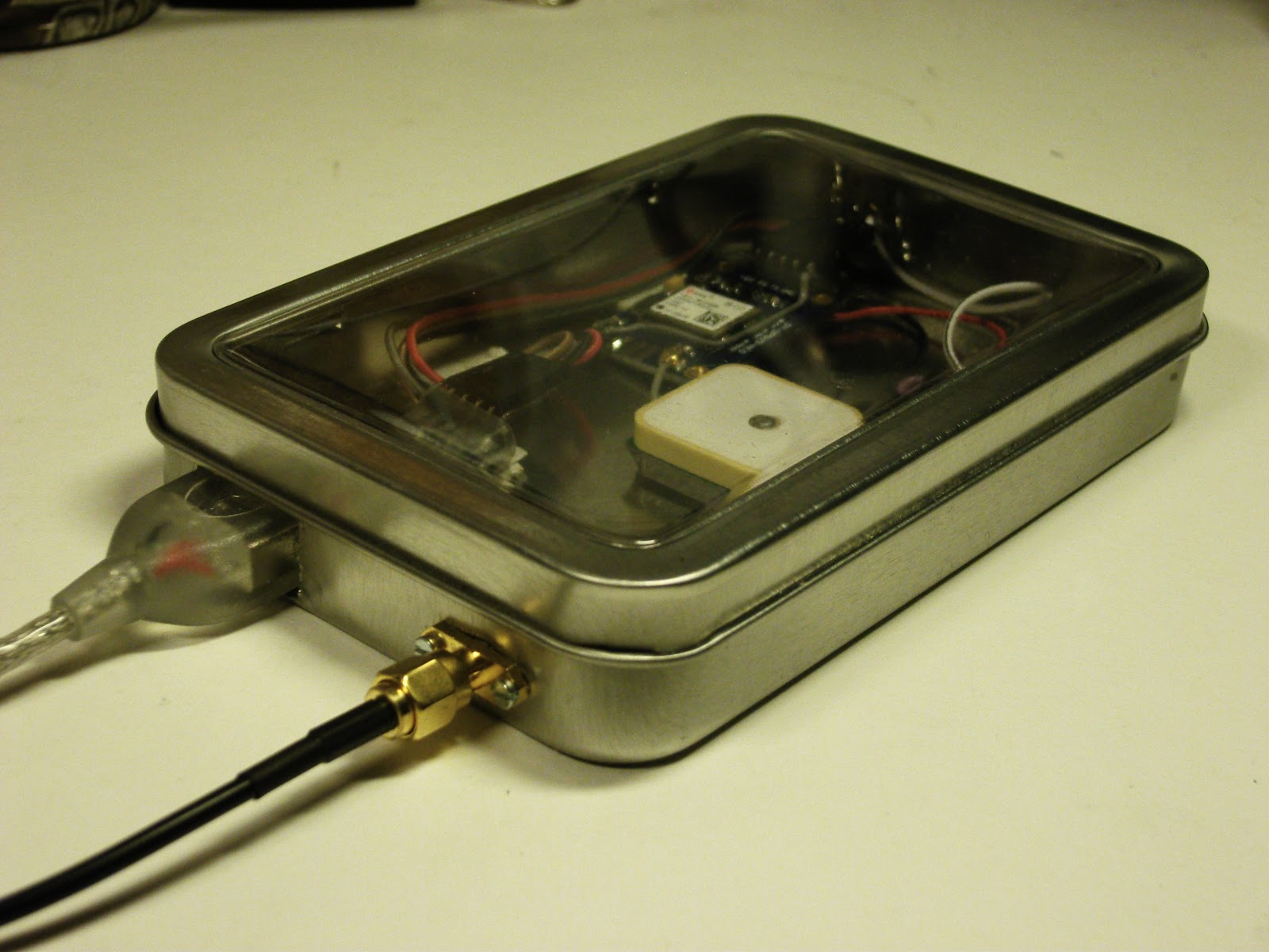
I had some trouble closing the lid on the “Just good enough 10 MHz GPS reference” due to the size of the BNC jack. Therefore I changed it to an SMA (SubMiniature version A) female jack. A thin cable connects it to the K3’s SMA input and there is no need for any SMA-BNC adapter on that end.
At the same time I moved the GPS antenna to a more central location in the tin, in the hope that the walls of the tin would interfere less with GPS reception. That’s the theory anyway, if it matters much in practice is a different story.
 Actually, I think I’m going to use SMA more often with these clear top tins and also Altoids tins. They take up much less space and are easier to install and to work with.
There aren’t any high power applications for circuitry in such tins, so I cannot so any reason why the SMA won’t work just as well or even better than the BNC.
Other related posts about the 10 MHz reference:
- Just good enough 10 MHz reference (3 Oct 2015)
- Curing amnesia in the 10 MHz GPS reference (19 Nov 2015)
- Improved GPS reception with a ground plane (11 April 2016)
Just good enough 10 MHz GPS reference
Some time ago I noticed that the Ublox Neo-7M GPS has a 10 MHz output which is locked to the GPS system’s accuracy. Most people kept saying how useless it was due to excessive jitter unless it was cleaned up with a phase locked loop of some sort.
At about the same time I installed the external reference input for my Elecraft K3. The K3EXREF enables the K3’s frequency to be locked to an external 10 MHz reference. What struck me was how its function is described:
- The frequency of the internal oscillator of about 49.38 MHz is continuously measured and averaged, obtaining a value to the nearest 1 Hz.
- The K3EXREF does not phase lock the K3’s reference oscillator and the external 10 MHz source has no impact on the K3’s phase noise performance.
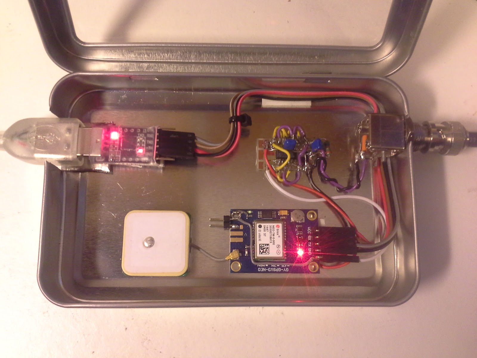
This got me wondering if the Neo-7M would be just good enough as a reference and that all the averaging internally to the K3 would take care of the jitter. I ordered one from Ebay for USD 12-13 together with an USB interface (USD 1.5) and hooked it up. (Actually the NEO-7M already has a built-in USB interface, but my board doesn’t support it). The result is shown above as assembled in a clear top tin. In my wooden house I can receive GPS indoors, so I have no need for an external antenna
 The K3 accepts the input and I see the star in REF*CAL blinking. Just after turn-on of the K3 my 49.38 MHz reference frequency ends in …682 and after 10-15 minutes it has fallen and stabilized to …648, i.e. 34 Hz down in frequency. This is just 8 Hz off the reference value I determined manually was the right one when my K3 was new in 2009 (49.379.640).
All this taken together indicates to me that the K3 finds this 10 MHz acceptable for locking. The measurement to the nearest Hz, implies a measurement time of the order of 1 second and that seems to be enough to smooth out the jitter from the Neo-7M.
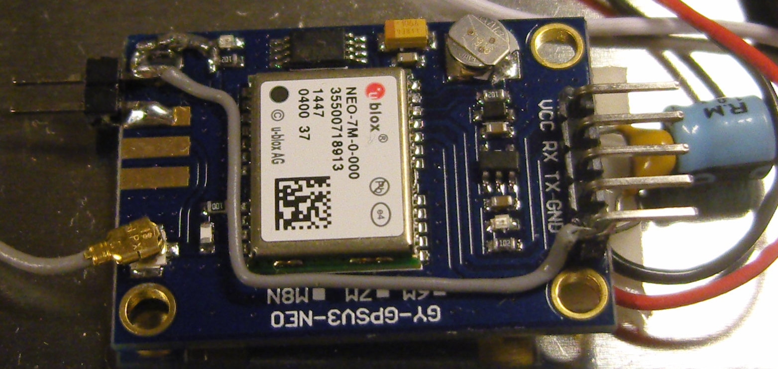
In order to get this to work I had to do some modifications to the GPS unit. First I had to get access to the timepulse on the chip’s pin 3. My connection is inspired by that of G4ZFQ and consists of a small wire from the left-hand side of the 1k resistor to the upper left hole. From there another grey wire goes below the chip and to the 5-pin header which is soldered to the Vcc, Rx, Tx, Gnd pins. The 5th pin is cut off and is just attached to the other pins through the plastic hardware.
The second modification was required in order to get it to run from the somewhat noisy USB 5 Volt supply. That took some decoupling between the Vcc and Gnd pins (220 uF and 0.1 uF in parallel), visible to the right in the image above, using good engineering practice to keep the wires as short as possible.
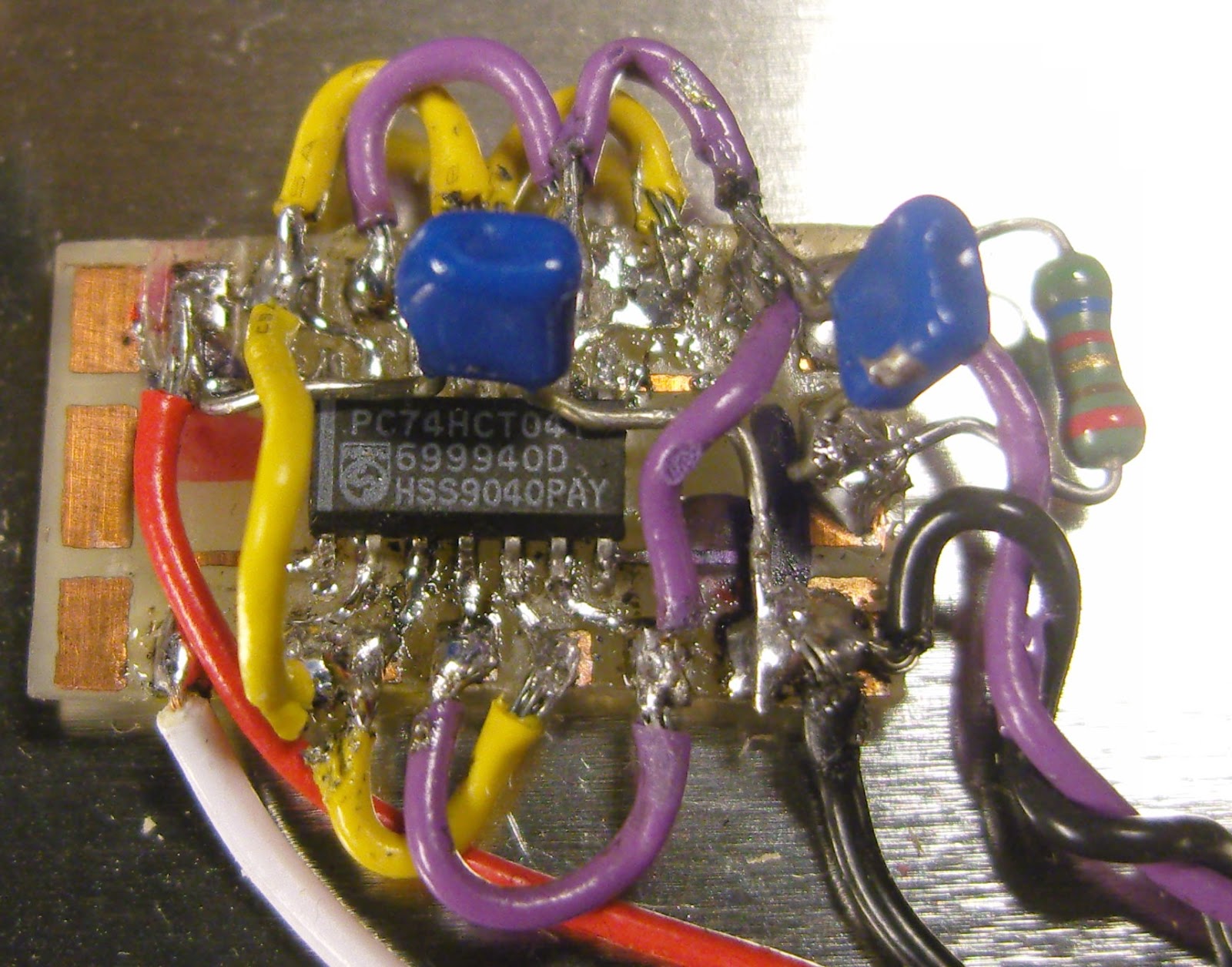 The timepulse is a 3.3 Vp-p output which cannot drive anything below 400-500 ohms impedance. Therefore I added a 74HCT04 driver that I have assembled on a little homemade SMD to DIL adapter PCB (easy to find on Ebay). It serves as a driver to feed the 10 MHz to the 50 ohm input of the K3EXREF.
The HCT04 IC has 6 inverters. One of them takes the input signal from the Timepulse output of the GPS IC and buffers it to drive the 5 other inverters in parallel. This is shown in the schematics at the end of this blog post.
The 5Vp-p output from the buffers is fed via 56 ohms to a connector that goes to the K3EXREF input. This is in accordance with the K3EXREF manual which says: “The 10 MHz source should have a signal level between +4 dBm and +16 dBm, nominal. For square wave sources, 2VDC to 3.3VDC peak is optimum. If the source is a 5V logic level, use a 50-ohm resistor in series with the input.“
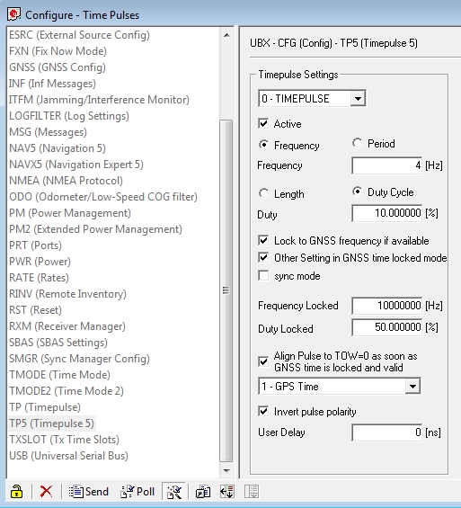 In order to set up the GPS I have used the u-center program (Menu: View, Configuration View, TP5 (Timepulse 5)) from Ublox and set it up with the parameters shown to the right. It blinks at 4 Hz before the signal is acquired and then switches to 10 MHz. This can be observed on the green LED connected to the Timepulse output also as it switches from blinking to a half-lit status.
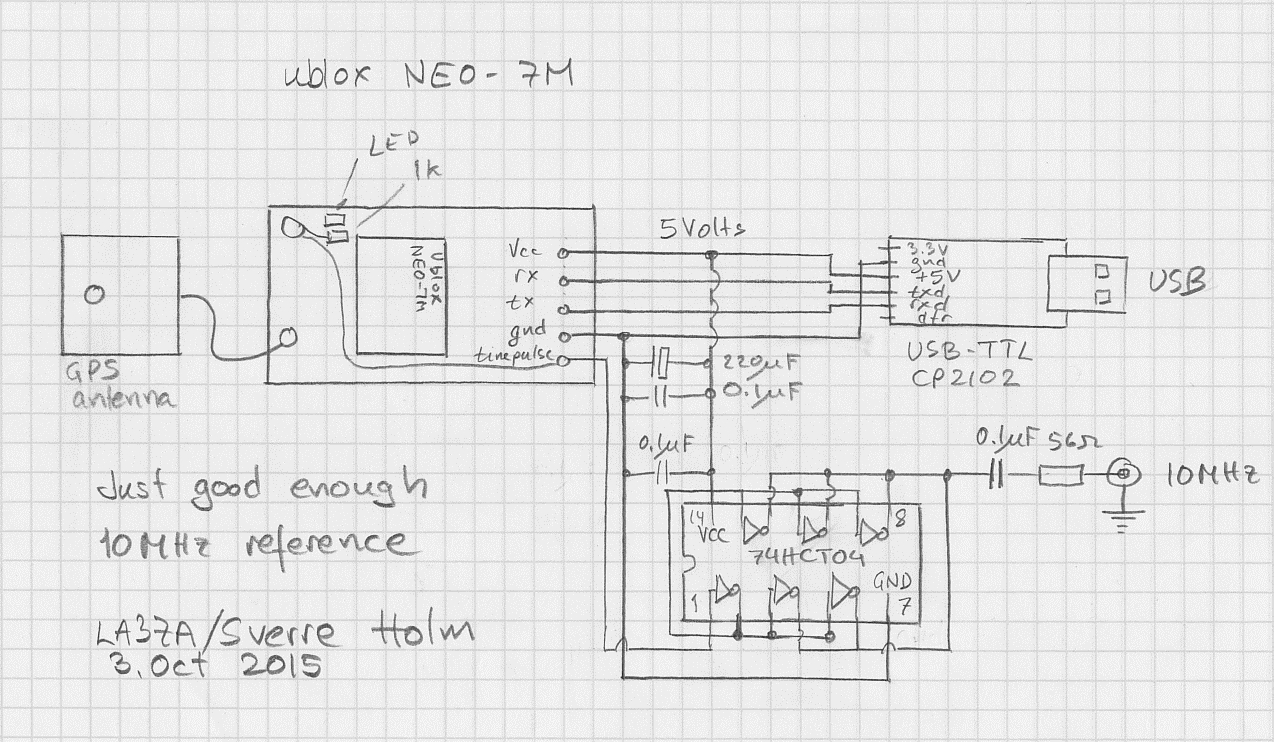
See also
Where can I get APF and DIV stickers for my K3?
The updated Elecraft K3, the K3S has some nice improvements that would be nice to have, but which I also can live fine without. But even an old K3 can be updated to some of these improvements They are detailed on the Elecraft K3S FAQ.
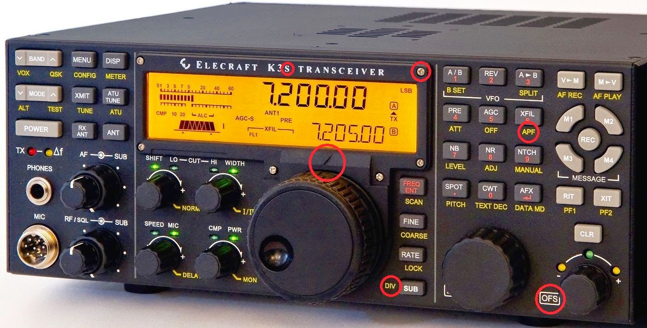
I studied the front panel for differences and put red rings around them. The three to the upper left have to do with the new display bezel with silver instead of black screws, the S in K3S, a built-in marker for the VFO A knob, and a soft-touch VFO A knob.
In addition to the marking with OFS (offset) to the left of the RIT/XIT control, there are two markings that also reflect what my present K3 with the latest firmware does:
- APF instead of DUAL PB (Audio Peaking Filter – Dual Passband) – upper right
- New marker for DIV – Diversity reception – to the left of VFO A
Where can I get APF and DIV stickers for my K3?
The updated Elecraft K3, the K3S, has some nice improvements that would be nice to have, but which I also can live fine without. But even an old K3 can be updated to some of these improvements. They are detailed on the Elecraft K3S FAQ.
I studied the front panel for differences and put red rings around them. The three to the upper left have to do with the new display bezel with silver instead of black screws, the S in K3S, a built-in marker for the VFO A knob, and a soft-touch VFO A knob.
In addition to the marking with OFS (offset) to the left of the RIT/XIT control, there are two markings that also reflect what my present K3 with the latest firmware does:
- APF instead of DUAL PB (Audio Peaking Filter – Dual Passband) – upper right
- New marker for DIV – Diversity reception – to the left of VFO A
Notes and Ramblings
Three perhaps noteworthy amateur radio activities occurred recently around K8GU: 1. During the course of some HVAC upgrades, I was able to get two holes core drilled through the foundation to bring coax and control cables into the house; 2. I operated in the NAQP August CW contest; 3. Evan and I went to the Berryville, VA, hamfest.
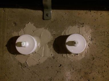
These two ports exit the basement into a crawl space where I will ground the cables before they enter the house. I still need to get some hydraulic cement or other quick-setting patch mortar to clean up the drill crater on the outside. Total cost: $5 in materials and a large pizza for the crew.
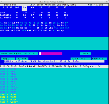
Screenshot above shows TRLinux after the end of the contest (obviously it was today, not last night). TRLinux performed flawlessly again with the YCCC SO2R+ box driving the KK1L band-decoder and 6×2 switch. I operated for about five hours (probably a little more, and definitely more if I used the NAQP 30-minute time-off rule to calculate it). I got up after my first operating sitting at the beginning of the contest and left the shack. As I exited the door, I was hit with the smell of hot electronics. You know the smell: like when you just let the smoke out of a transistor. I walked over to the antenna switch matrix where I was using a triplexer to split the hexagonal beam to both radios. It was warm to the touch. It seems to have continued to function, but I’ll have to disassemble it at some point to see if any irreversible damage was done.
The August NAQPs are always fun for us out East because there is the ever-present opportunity for sporadic-E throughout the contest, giving us a chance to work nearby states, which can really drive up the multiplier (and QSO, depending on the direction of the opening) total. Of course, this is the real boon of having a second radio: you can call CQ on your most productive band while looking for openings on the others. I came down after supper with the family to “work 40 meters before it goes long” and ended up with blistering 10- and 15-meter runs into the Midwest and South. Since Evan and I were planning to go to the hamfest and I don’t yet have a 160-meter antenna at the “new” QTH, I pulled the plug at midnight local time (0400). Not sure 40 meters was even getting long at that point. At any rate, it was wonderful to say “hi” to so many old friends from MRRC, MWA, SMC, PVRC, and beyond!
A final comment: You can really tell how much better one radio is than another when you have them both side-by-side on your desk. This was quite apparent when I had the K3 and the TS-930S and it is also apparent with the K3 and the K2. The K2 is a wonderful radio and fun to operate, especially in the field, but it’s not the K3 as far as fit and finish, among other things. No, I’m not buying another K3 anytime soon. The K2 is quite enough for the second radio.
I’ve always heard that the Berryville, VA, hamfest had a good boneyard/fleamarket/swapmeet but I’ve never managed to attend. I resolved to attend this year and was pleasantly surprised. Evan came along for the ham-and-egg breakfast, which was good but he rejected the ham after only consuming about 1/3 of it, and a trip to the playground at the school across the road. This is still a “real” hamfest like the ones I remember going to in the early 1990s before eBay and online trading really took the wind out of swapmeets. There were plenty of rigs spanning the spectrum of boatanchor to relatively modern, HF and VHF/UHF. There were lots of amplifiers, as well, (and a small quantity of CB junk; Texas Star, anyone?) There were also lots of antennas, and even some Rohn 25. The computer and cell phone accessory dealers were mercifully few and there were lots of tables of parts, bits and pieces. This is a ham’s hamfest and I’ll be returning. I picked up a bunch of Cinch-Jones plugs and sockets for my new cable ingress, plus some SMA connectors and flexible coax jumpers. Plus, I ran into a few friends, although not the ones I expected to see!
Remoting K8GU…kinda
We welcomed our second child, a daughter, into the family last week. Since she is our second, the time in the hospital was more about making sure she was healthy than us learning all the ropes. So, I had some undisturbed time to read on the Internet with a sleeping baby on my chest…and wish I could remote control my station.
Having been party to the discussion surrounding remoting a local contest station (K4VV), I had seen enough traffic about different VOIP options to start with Mumble for the audio stream. I set up a Mumble server on my Linux server at the house, and then setup the Mumble client on my hamshack computer. I ran a 1/8-inch TRS cable from the rear-apron line-out port of the K3 into the line input of one of my sound cards on the computer. I put a free Mumble client on my iPhone and viola! It worked out of the box.
I have been using Pignology’s HamLog on my phone for quick logging of one-off QSOs and goofing off with its vast array of tools. HamLog also has the ability to remote control a rig using Pignology’s hardware. Since, I’m really not in a good position to drop $300 on a box I’ll use a couple of times per year, I reasoned that there might be an alternative. Enter the socat utility:
root@tula:~# socat /dev/ttyUSB1,raw,echo=0 tcp-listen:7373,fork
Freakin magic. I used HamLog to connect to a “Remote PigTail” and it mostly works. The frequency display does not seem to work and HamLog loses the connection if the phone falls asleep. But, it is functional. Another interesting wrinkle is that when my shack PC screensaver comes on, it mutes the audio stream piped into Mumble. But, those are all minor irritations at this point considering the trivial amount of effort that went into getting a remote control going…
Clever K3 macro trick

Tonight I sat down to fiddle with the macros of my Elecraft K3. As I already use M1-M4 for CW memories, I only had the PF1 and PF2 buttons available.
It was the blog post “K-3 Rotating Macros” of W8TN that made me aware of a clever trick for using a macro to reprogram itself. This gives the possibility to have two rather than one function in the PF2 button. My need is for a button that can toggle between the typical pile-up functions Split+1 and Cleanup. In addition I have another macro that toggles speakers on and off.
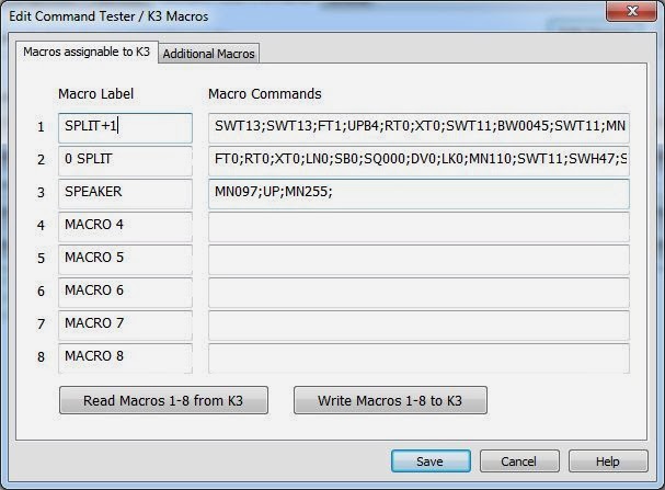
The two first macros resemble those of W8TN, but are not quite the same:
- Split+1: SWT13;SWT13;FT1;UPB4;RT0;XT0;SWT11;BW0045;SWT11; MN110;SWT12;SWH47;SWT14;
- 0 Split: FT0;RT0;XT0;LN0;SB0;SQ000;DV0;LK0; MN110;SWT11;SWH47;SWT14;
The Split macro in memory 1 means:
- SWT13; taps A>B once to copy VFO A frequency to VFO B
- SWT13; taps A>B again to copy all other settings to VFO B
- FT1; enters Split mode.
- UPB4; moves VFO B up according to setting 4, which is 1 kHz
- RT0; turns RIT off
- XT0; turns XIT off
- SWT11; taps A/B to go to VFO B
- BW0045; sets bandwidth B to 0.45 kHz
- SWT11; taps A/B to go to VFO A
- MN110; enters Config, Function, Macro
- SWT12; taps the (2) button to choose Macro 2
- SWH47; holds the PF2 button to assign it to PF2
- SWT14; taps the Menu button
Entries 10-13 are the reprogramming steps where the PF2 button is reassigned to the cleanup macro in memory slot 2. The contents of that macro is:
- FT0; turns Split off
- RT0; turns RIT off
- XT0; turns XIT off
- LN0; unlinks the VFOs
- SB0; turns subreceiver off
- SQ000; turns squelch off
- DV0; turns diversity mode off
- LK0; unlocks VFO A
- MN110; enters Config, Function, Macro
- SWT11; taps the (1) button to choose Macro 1
- SWH47; holds the PF2 button to assign it to PF2
- SWT14; taps the Menu button
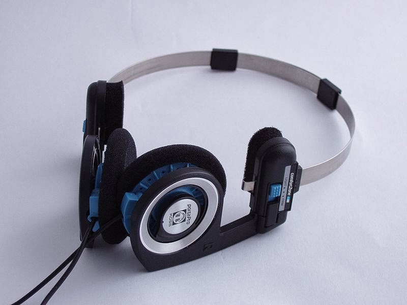 |
| Picture of Koss PortaPro from Wikipedia (Malcolm Tyrrell) |
Since I often toggle between speakers and my Koss PortaPro headphones (connected to the back of the K3), I liked what I just found on the Elecraft list where the command for speakers on/off was reposted. I have assigned that to the PF1 button which is also the RIT (Receiver Incremental Tuning) reminding me that this affects reception.
Macro 3 is MN097;UP;MN255; meaning:
- MN097; Access Menu, Speaker+phone
- UP; Change parameter
- MN255; Access Menu, Exit
After the macros have been loaded into the K3 with the K3 Utility Program, the macros are assigned to the PF1 and PF2 buttons by first entering Config, Macro 3, and then hold PF1, and then Config, Macro 1, and then hold PF2.


