Posts Tagged ‘JT65’
 Near miss – 11742km on 10m JT65
This evening CA3SOC (Chile) was calling CQ on 10m JT65. I called and called him – he called CQ about 14 times – but I was unable to raise him. At the start he was -16dB S/N but in the end was down to -22dB S/N. I was copied in Sweden at the same time, but that was no compensation.
Earlier in the afternoon I worked an E74 on PSK63, my first ever QSO on PSK at that speed. I am finding real-time keyboard operating in PSK modes quite “challenging”. Whenever I use the keyboard e.g to write this blog, I make lots of errors that need correcting. This is hard on PSK31 and PSK63 in real time. JT65 and JT9-1 are a lot easier. Currently I am using Digipan software which is simple and basic for PSK modes. I am using WSJTX V1.3 r3673 for JT65 and JT9-1.
Continuing JT65/JT9 today
When we get back from shopping I shall return to JT65-HF and JT9-1 modes hoping to work more stations. Yesterday, staying on 20m, I worked 4 Europeans running 2.5 or 5W. JT65-HF is very intuitive and works well. Althought I have had JT9-1 QSOs on 10m in the past, I suspect the rig stability is “challenging” and JT65-HF gives me a better chance. JT65-HF is some 4dB worse than WSPR but the TX period is only 48 secs (1 minute TX period but actual TX is less) so may be better with QSB? JT9-1 is a narrower bandwidth mode than JT65-HF and is about 2dB worse than WSPR. Of course, JT65 and JT9 are proper QSO modes.
Sunspot count today is 76 (decent) and 20-30MHz conditions are supposed to be “normal” so there could well be some F2 (as well as Es) on 10m today. JT65-HF and JT9-1 on 10m are calling I think.
The great advantage of WSPR is you can set the rig running and monitor things in another room. JT65 and JT9 seem to require “hands on” operation, which is fine.
Been a busy boy
JT-65HF
I have been using my newly built datamode interface in anger.
As well as running WSPR on occasion I have also been active using JT65-HF.
JT65 is a communication mode developed by Joe Taylor, K1JT, (specification here) originally intended for amateur radio communication with extremely weak signals such as Earth-Moon-Earth (EME) contacts on VHF it has gained popularity on the short wave bands using JT65-HF an adaptation of the JT65A protocol.
Being restricted to 10W it is an attractive method of making contacts. The protocol includes error-correcting features that make it usable even when the signals are too weak to be heard or are being subject to interference.
There are several how-to guides available
Get On the Air with HF Digital (from the ARRL)
JT65-HF -- an 'Odd' but Fun Digital Mode (from eham.net)
A number of software packages support JT65, the most popular being JT65-HF originally developed by Joe, W6CQZ. Sadly Joe is no longer developing the software, but the last version released still works, and is available at http://sourceforge.net/projects/jt65-hf/
Thankfully the project was open source and Beat Oehrli, HB9HQX as developed his own version with the catchy title JT65-HF-HB9HQX-Edition, available at http://sourceforge.net/projects/jt65hfhb9hqxedi/ This is the version I have been using with great success, the colour coding and simple button pressing makes a QSO straight forward and the built in logging and exporting make uploading to QRZ, eQSL and HRDlog painless.
Whilst to a traditionalist amateur operator it is perhaps a little slow, remote and impersonal (each exchange occurs during alternate minutes) I really like it! One advantage is I can set up the radio in the shack with CAT control via HRD and then have QSOs while VNC'ing into the computer from the laptop whilst in front of the TV with the wife and the dogs! (Thanks Tim G4VXE for that suggestion!)
I have been active on the 10/20/30 and 40M bands over the past few weeks making contacts with Bulgaria, Canada, Denmark, Germany, Greece, Iceland, Kazakhstan, Poland, Russia, Serbia, Sweden, Thailand, Ukraine, USA and Venezuela.
Contesting 'DX' Headset and Interface
I have become hooked on the RSGB UKAC VHF contests, operating on a Tuesday evening on different frequencies (50MHz, 144MHz, 432MHz depending on which week of the month) Whilst my results are small-fry compared to the big guns I have been more than happy with my modest antenna set up and less than ideal location (previous blog posts)
I soon appreciated that using headphones rather than the speaker made life easier but I was still using the stock supplied hand microphone. Several times I have found it difficult to make myself understood and suspected that not only am I plagued by my 'Black Country' accent and poor enunciation but maybe the microphone wasn't quite cutting it.
Not able to afford or justify the purchase of a Heil headset just yet I took inspiration from Charlie M0PZT and his recommendation for a budget solution using a £10 computer headset from CPC (product AV21444).
On the Yaesu FT-857D the microphone connector is a 8-pin RJ45 socket which is behind the removable front panel with the lead coming out of one of a number of openings. Whilst the panel is easily removable I didn't want to keep removing it when switching between microphones, also re-purposing an obvious CAT5 network lead was problematic as they are often thicker than the openings.
 | |
| The lead removed from MH-31, RJ45 on interface |
 |
| Mic lead connected and headset |
 |
| The budget 'dx' headset |
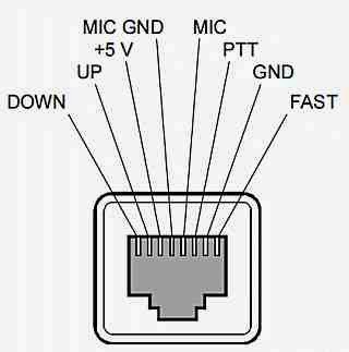 |
| Yaesu FT-857D mic socket as view from front |
The box also has a PTT switch, this could have simply grounded the PTT line but I wanted to have a LED indication on the box and again I could have just wired a LED and resistor to 5V and to the PTT line so it would light when the switch was closed, pulling PTT to ground and completing the circuit. I opted to use a simple transistor open collector switch to add a little isolation.
The interface works well and I used it for the first time last night in the 50MHz UKAC with my homebrew MOXON antenna...
6M/50MHz MOXON
My first contest back in January was the 50MHz UKAC and as I blogged I made a solitary contact due to antenna issues, i.e I didn't really have one!
I missed the February contest so this month I really wanted to have a decent stab at it which meant building an antenna. I decided early on that a Moxon was probably the easiest to construct, so I downloaded the MoxGen program to calculate the element lengths.
Using 1mm diameter 'garden wire' for the driven element and reflector. I had various bits of flexible plastic pipe kicking about and decided to use them to construct an x-shaped spreader, unfortunately the pipe was obviously from different batches and as soon as it was tensioned by the wire it bent into all sorts of strange shapes due to the different elastic properties so I abandoned that design.
I had left the build to the last minute and needed a quick solution, so yesterday morning plan-B was to go an get some cheap timber from the local B&Q on the way to work and build a simple frame to wrap the wire round.
 |
| Moxon on garage floor |
 |
| Coax and common-mode choke, and sturdy support! |
One thing I hadn't appreciated was just how big the final antenna was, it wasn't heavy just big! So last night an hour before the contest started I fitted the choke balun and coax to the terminal block. To be safe I removed the other antenna from the mast and hoisted her up.
 |
| Up in the night sky |
Moment of truth, thankfully the VSWR was around 1.5:1 at 50.2MHz, rising to nearer 2:1 at the top end of the band. Not ideal but close enough. The VSWR measurements would suggest that the Moxon is a little bit long, interestingly some online Moxon calculators suggested dimensions for a slightly smaller Moxon than the downloaded Moxgen program did? Something to tweak/experiment with possibly using some thicker wire to increase the bandwidth.
50MHZ UKAC 25 March 2014
I was sorted! Moxon antenna up, contesting headset and interface plugged in and a quick scan up and down and I could clearly hear several stations testing and setting up. I poured myself a beer and soon the contest started.
 |
| Time between QSOs for a 'selfie' |
I was not disappointed in fact I was quite happy with what my 10W, my new headset and home brewed antenna had achieved. The Moxon showed great promise and directional characteristics but for some reason just couldn't get south as the map indicates.

Out of interest I wondered what the line of slight view from my mast looked like so I strapped a camera on to the moxon this afternoon..
Need more height I think, especially if pointing South and a rotator would be nice!
Well that wraps it up for the moment.. 73
An Amazing Moment in Space Weather – Massive Solar Eruption June 2011
While many are talking about how Solar Cycle 24 is the weakest since the Maunder Minimum (the period starting in about 1645 and continuing to about 1715 when sunspots became exceedingly rare, as noted by solar observers of the time — see this Wiki entry), there are moments when activity on the Sun strongly increases, providing brief moments of excitement.
Here is a case in point, witnessed by the Solar Dynamics Observatory (SDO; see SDO Mission) on June 7, 2011, when the Sun unleashed a magnitude M2 (a medium-sized) solar flare with a spectacular coronal mass ejection (CME). The large cloud of particles mushroomed up and fell back down looking as if it covered an area almost half the solar surface.
SDO observed the flare’s peak at 1:41 AM ET. SDO recorded these images in extreme ultraviolet light that show a very large eruption of cool gas. It is somewhat unique because at many places in the eruption there seems to be even cooler material — at temperatures less than 80,000 K.
This video uses the full-resolution 4096 x 4096 pixel images at a one minute time cadence to provide the highest quality, finest detail version possible. The color is artificial, as the actual images are capturing Extreme Ultraviolet light.
It is interesting to compare the event in different wavelengths because they each see different temperatures of plasma.
Credit: NASA SDO / Goddard Space Flight Center
Video: http://g.nw7us.us/1aOjmgA – Massive Solar Eruption Close-up (2011-06-07 – NASA SDO)
Visit: SunSpotWatch.com
Overmodulated JT65 on HF?
Sometimes it is crowded on JT65 on HF due to too little bandwidth. When only 2 kHz is available and each signal needs 175 Hz that’s understandable. But then others seem to complain that some overmodulate their transmitters so that they occupy more than the 175 Hz, making it even harder to fit an extra signal in the band.

My first impression from using the new JT9 mode is that the problem is much smaller there than for JT65, so maybe something like what I am discussing here has been done in the decoder software. But as far as I know, the source code has not been releasted into the public domain yet by K1JT, so I cannot verify it now.
But it seems clear to me that what looks like splatter has much less to do with overdriving and overmodulating transmitters than one may think, and more to do with the particular way that the spectral estimate is found in the JT65 decoder software. Combined with the variable propagation which is an intrinsic feature of HF and which may create a highly variable signal strength, this is what seems to create the spillover.
Show Notes #083
Introduction:
- Back from Dayton and ready to go.
Topics:
- Dayton Hamvention 2012
- LHS had the same booth as last year at North Hall #131. Estimated attendance was 25,000 individuals. Russ recounts the experience. Thanks to Matt, KC8BEW, who stopped by and helped out at the booth. The LowSWR podcasters stopped by, too.
- FCC Dismisses Texas Ham’s Fourth Petition, Calls it “Repetitive”
- Our hosts discuss.
- Contest logging for Linux.
- Several people at Hamvention asked about contest logging software for Linux, but Russ was at a loss for a recommendation. Upon his return, he discovered…
- SO2SDR Contest Logging Software
- Stefano, IZ3NVR/KD2BGM was trying to get so2sdr to work under Linux Mint and while it would compile, it did not run, so Russ set about trying to get it going.
- It’s not packaged for Debian or Fedora, so it must be built from source, available at the link above.
- The program is written in Qt, so it can be run on devices which support that environment, including Linux and Windows. Of course, Qt must be installed in order to compile so2sdr.
- Russ also had to install the following packages on his Linux Mint machine: portaudio19-dev (NOT libportaudio-dev; apparently, libportaudio-dev is too old), fftw3 and fftw3-dev
- The compilation procedure consists of:
qmake make sudo make install - so2sdr compiled and ran fine. It did complain that it wanted a parallel port for switching between radios, but you can ignore that if you don’t need to do that.
- Russ gives an overview of the features and capabilities.
- There are a few drawbacks:
- An apparent lack of SSB support? It seems to be CW-only.
- Frequency input checking is broken.
- Keystrokes are not intuitive, but are well-documented.
- However, the built-in help file is quite useful.
Feedback:
- E-mail from Larry, KG4Q, extolling fldigi and JT65-HF. He wishes there was a version of JT65-HF for Linux. Well, Larry, there is! You can download the source here. Also, WSJT does JT65, too.
- Chris, K4FH, caught up with Russ at Hamvention and talked about his Linux in the Ham Shack presentation. He managed to put together a fine bunch of slides completely without our help. Sorry, Chris!
Contact Info:
- Contact Richard at [email protected], Russ at [email protected], or both at the same time at [email protected].
- Listen to the live stream every other Tuesday at 8:00pm Central time. Check the LHS web site for dates.
- Leave us a voice mail at 1-909-LHS-SHOW (1-909-547-7469), or record an introduction to the podcast.
- Sign up for the LHS mailing list.
- Sign up for the MAGNetcon mailing list.
- LHS merchandise is available at the Merch link on Web site. Check out the Badgerwear or buy one of the other LHS-branded items at PrintFection.com/lhs or Cafe Press. Thanks!
- Thanks to Dave from Gamma Leonis for the theme music.
Music:
- “Down Today” by Jonathan Coulton from the album “Artificial Heart”.
- “Sucker Punch” by Jonathan Coulton from the album “Artificial Heart”.
JT65HF problems
There re just a ton of data modes you can play with and this morning was the turn of JT65-HF to be on my screen. I’d installed it quite a while ago and not used it for some months but I thought I could do with giving it a quick run through to remind myself of the protocols in case we use it on the SOS radio week operations (as GB4LBC for St Bees lifeboat station).
Time is very important with JT65 and a few other modes and I’ve never been a big fan of windows time setting utility. It never seems to be right and there is always a problem with either this or that. I use Dimension 4 on XP machines and it works very well. Under Windows 7 you have to remember to run it as an administrator so I suspect the same will be true for Vista. there seemed to be a bit of a conflict going on on my puny little computer so I had to reinstall JT65-HF and only then did it start to decode the received signals.
I took the opportunity to use my stealth antenna (A Watson 80 plus 2 dipole – which is really only good for 20m here) and immediately got a contact with DG8RW & W3PV with 15 watts.  I had a bit of trouble with the first contact as he couldn’t copy my signal report for a while and I had to resend it quite a few times before he got it. Eventually we got a QSO together and that was pretty pleasing.
So I’ve got my hands dirty again with JT65 and whilst its not the most interactive of modes it reinforces the fact that SSB is inefficient in comparison as I doubt I’d have got where I did with 15 watts and a loft mounted antenna. Still, it was a nice distraction from what I should have been doing. That was to be revising for an exam on Tuesday. Nothing exciting, a professional exam and much less enjoyable that playing with radios.


