Posts Tagged ‘home-brew’
 Foxx 3 TRX build
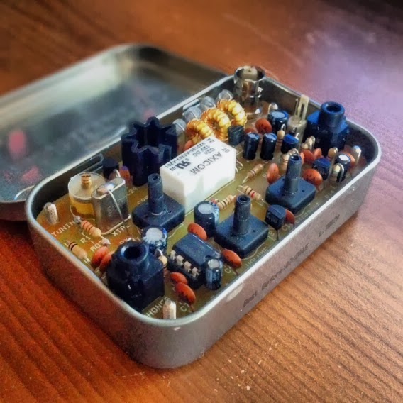 So it was my birthday recently and to celebrate the turning of another year and that I had indeed taken a day off – I decided to build a FOXX 3 QRP CW transceiver. These little kits are available from Kanga-products.co.uk and are designed to fit in a Altoids tin.
The kit comes pre bagged up in separate bags, and its just a case of soldering the correct component to the correct area on the circuit board. The kit itself is a 1 Watt QRP transceiver that can be bought on various bands. Mine was for the 20m band.
The board has a clear and easy to read Silkscreen and the pads are suitably wide enough to allow anyone with different levels of skill to create the kit. Each step allows you to test each part of the board, so you learn how each part of the kit relates to the transceiver as a whole.
I had a great time building it, it’s a simple, easy and great fun little kit. I hope to take it out and about – so hopefully you can hear my tiny signal on 20m soon.
Harold’s JA7HJ tower was not your average tower

Harold’s 30′ JA7HJ tower (Click to enlarge)
I meet some very interesting people in radio circles. My friend Harold Johnson (W4ZCB) is undoubtedly one of them.
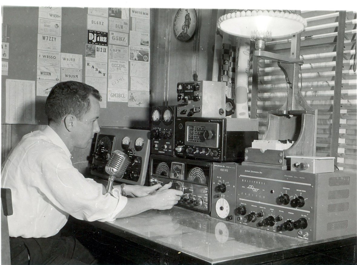
Last year at my local ham radio/DXer club meeting, members were asked to bring photos of shacks and rigs, and describe our evolution as ham radio operators. In the series of photos that arrived at the following meeting, one in particular stood out: Harold Johnson’s radio tower in post-war Japan.
Johnson’s tower stood almost thirty feet tall and supported a 20 meter Yagi which you can see in the above photo. Johnson, who at the time operated under the callsign JA7HJ, also had a little ham shack built. The shack materials–including the tower, Johnson recalls–cost him “three bottles of Scotch for the army quartermaster…I paid the Japanese builder $15 or $20 for the complete enchilada.” This tower was built entirely of wood: the vertical members were 2′ x 4’s, the slats were 1′ x 3’s.
Of course, the tower didn’t have a mechanical rotor; instead, Johnson climbed inside the tower, lifted the wooden boom, rotated it manually, and placed it back on the uprights.
When asked how he powered his station, Johnson pointed to the wheeled generator in front of the radio shack in the photo. “The generator was called a B6B–it produced 24, 120, 240, and 480 volts, and was rated 10 kW.” When I asked how he managed to procure the generator, he replied that he “borrowed it from the flight line, which was about 300 feet away.”
Johnson’s Nashville, TN shack, circa 1955/56. (Click to enlarge)
I always enjoy hearing personal histories in radio and I didn’t doubt for a moment that Harold Johnson’s would be intriguing, so I asked if he’d tell us how his interest in radio began. So, here’s Johnson’s story in his own words:
As a preteen, (and poor as a church mouse during our previous
Depression), I would visit my aunt and uncle in the summer, likely due to the fact that they were farmers and had food to eat. They owned an old Philco radio that had shortwave bands and I was intrigued with the phone amateurs on the 80 and 20 meter bands. Often, I could hear both sides of the conversation, after I found out that they were on various different frequencies, being crystal controlled back then! My…How times have changed.In high school, I found another afficianado, and can recall melting “Woods metal” in boiling water and floating a piece of Galena on it until it returned to a solid and [thus] made my own crystal set. WWII had started by then, and I would listen to the ground-to-air communications between ships in Lake Michigan and pilots taking off and landing on them. Great DX, perhaps 10 miles away.
In 1943, I had graduated from high school and joined the US Army Air Corps. Went through training and was still in training (…to be a pilot until they counted airplanes and pilots and decided they had enough of each […so instead] turned me into a B-29 gunner). The war was over whilst [I was] still in training and I “retired” in November 1945. Went home and found my high school sweetheart, married, went back to school to finish my education and started the Johnson family. Still married, and
to the same girl. What a sweetheart to have put up with me all these years. [No kidding, Harold!]Went back in the US Air Force in 1949, this time became a pilot, and just in time to go to Korea for a year. However, during training, had to learn the Morse and if you learned to 13 WPM, you had a free hour and didn’t have to attend class. That overcame my obstacle to amateur radio, and I took the exams in 1950 and became W9PJO. Our rules at that time were that you had to hold a “class B” ticket for a year before you could take the “class A” exams. That year I spent in Korea and Japan and managed to obtain my first foreign call, JA7HJ.
Returning home to wife and by that time two children, I took the class A exams and became W4ZCB. I decided that I enjoyed flying, (at least most of the time), and decided to make it a career. The ensuing years, I was always on and in the air, and usually spent the winters in Alaska and the summers in the Canal Zone, anything to practice how to be miserable. Lebanon in 1958, Vietnam in 1968 and by 1969 decided that I should start doing something else before my luck ran out.
During my last 4 years of service I flew an Army four star around the world four times. Fortunately he was Ted Conway, W4EII, and we mutually enjoyed operating under a couple dozen different call signs from a lot of exotic (and several not so exotic) places. Had G5AHB back when the 5 was reserved for foreign nationals. We were good friends after we both retired (on the same day; I always liked to say that he couldn’t stand to serve without me) until his death in 1990.
I started a small company manufacturing electronic test equipment for public utilities; spent the next 20 years doing that (and enjoying a much more stable life with family and radio.) Managed to work all the countries (entities these days) there are, win a few contests from a contest station I built and operated for 10 years. (80, 40, and 20 in the front room, 15 in one bedroom and since 160 and 10 were seldom open at the same time, they shared the other bedroom. To change bands, you just changed chairs. Five big towers and Yagis, a VERY high maintenance hobby in the lightning prone state of Florida. (Let’s not mention hurricanes!)
Retired again to the beautiful mountains of North Carolina in 1986. A much more modest station these days, but active on all the HF bands. I really enjoy building homebrew radios and maintaining daily schedules with friends worldwide. Can be found daily on 21.203 with G3XJP and often joined by other builders of the magnificent PicaStar transceiver designed by him. Sixty-three years a ham, still enjoying it. It’s guided my careers and interests. What a wonderful hobby!

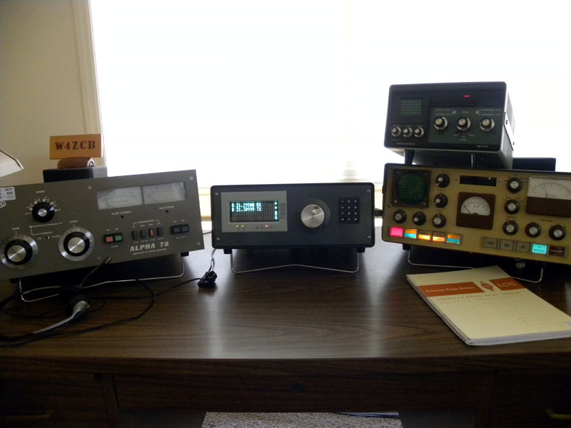
W4ZCB’s shack today is based around his home brew SDR transceiver, the PicaStar. (Click to enlarge)
Over the past few years, I’ve gotten to know Harold Johnson; I must say, he has to be one of the very few hams I know who knows the inner workings of tube/valve radios as well as he does the highest tech radios on the market, a rare talent indeed. If you’re trying to learn a bit more about the BC-348 series of radios and trying to diagnose a problem with it, Johnson’s your guy. If you’re trying to build an SDR from scratch, he’s also your guy. And clearly, if you want to hear a fascinating account of a life influenced by radio, this is most definitely your guy.
Thanks, Harold, for letting me share your story!
Check out Harold Johnson’s website by clicking here.
Get your head in the cloud.
Even though my day job is completely centered around Information Technology I still miss changes and shifts in technology that happen practically under my nose. As much as I hear vendors speak about “The Cloud” I haven’t had much time to investigate and discover if this “new technology” is something I can put to use.
If you already know what “The Cloud” is then you can skip the following paragraph, otherwise please read on:
The easiest way to understand the cloud is to think of it as a utility, like electricity. When you plug a device into a wall outlet, electricity flows. You didn’t generate the electricity yourself. In fact, you probably have no idea where the electricity was generated. It’s just there when you want it. All you care about is that your device works. Cloud computing works on the same principle. Through an internet connection (the equivalent of an electrical outlet), you can access whatever applications, files, or data you have opted to store in the cloud–anytime, anywhere, from any device. How it gets to you and where it’s stored are not your concern (well, for most people they’re not).
There is no end to the stream of interesting projects that are being developed “in the cloud” and its hard to keep track of them all. Some projects have turned into things that we’re all familiar with; Flickr, Facebook & Twitter are a few examples. Some appear and vanish like the proverbial “Flash in the pan” and, since you generally lose access once they run out of steam, it can be disappointing if you have invested any time in those applications.
I’ve collected a few cloud based applications/services here that might be of interest to the radio amateur and/or experimenter. They look like they should stick around for a while and have already reached a fair level of maturity:
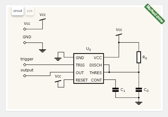
circuits.io: Described as a free circuit editor in your browser, it is actually a lot more. You can not only design practically any kind of circuit using just a web browser, you can turn that circuit into a printed circuit board and then BUY that PCB board online. Several different technologies had to come together to make this into an effective tool. This tool is fairly new but is becoming very popular. Hopefully it will stick around and continue to mature into something great.
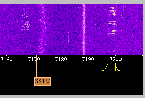
WebSDR: While arguably not a “cloud application” it does allow you listen to software defined radios, using a web browser, from anywhere you have internet access.
There are multiple sdr receivers located across the globe using a variety of receivers and antennas. Some are tuned to the HF bands while others cover VHF & UHF bands.
This is an invaluable free service provided by institutions and individuals at their own cost.
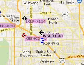
APRS.fi: The distributed network of Automatic Packet Reporting System stations, repeaters, clients and map servers could be considered to be “of the cloud” before the cloud even existed. With an APRS equipped radio you can log your position from a GPS, over the air & through another ARPS receiver. This is then sent out (usually) across the internet to other systems which in turn can map your location or update other APRS clients or radios. APRS has also been extended to include the ability to text message which is particularly useful in locations where cell phone SMS messages or email are not possible!
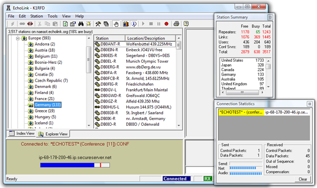
Echolink: Like APRS, Echolink links the Internet to amateur radio. However Echolink links the audio and PTT (push to talk) signals from a radio or software client to a radio in another physical location. If you’re stuck in a hotel room or another location without access to a radio you can still “get on the air” using an Echolink client on your Windows, Linux, iOS or Android computer & handheld device. Most Echolink connected stations are VHF/UHF but there are HF stations connected as well. Echolink is not designed to replace radio to radio communications but instead increases the connectivity of amateur radio operators and allows hams, who otherwise would not be able to operate, the pleasure of getting on the air.
As you can see, some of these “cloud apps” pre-date the idea of cloud computing by quite a while. Just another example of amateur radio folks being ahead of the curve without even realizing it.
Now I understand – Measuring capacitance with a micro-controller
The excellent article by Rajendra Bhatt explains not only how capacitance can be measured but also how a micro-controller can be interfaced to an analog circuit to create a useful piece of test equipment.
 |
| Capacitance meter by Rajendra Bhatt |
I found the explanation of the RC time constant method of measurement as interesting as the micro-processor project itself and congratulate Raj on demonstrating a practical and workable real-life example of what can normally be a dry textbook subject.
PC power supplies for Amateur Radio equipment?
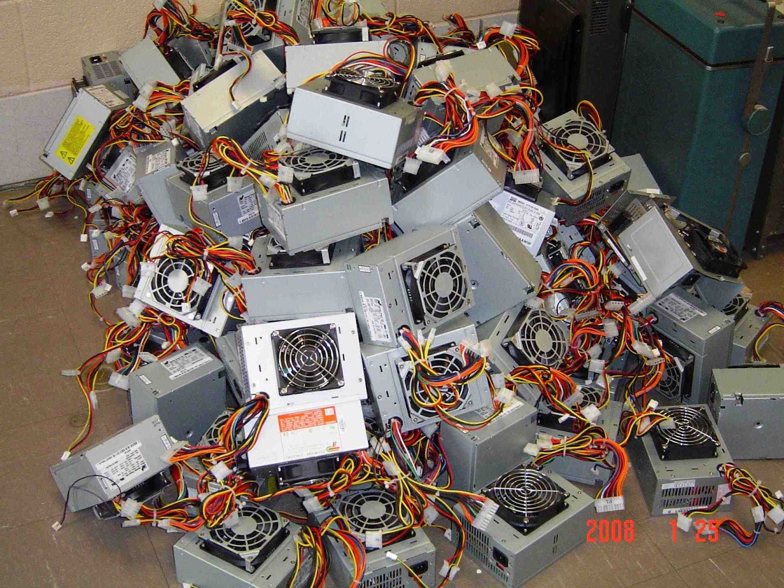
 I’ve noticed a few spirited discussions regarding modifying computer power supplies for use with Amateur Radio equipment. On the surface it seems as though they supply the perfect solution: Inexpensive, high current, regulated 12V DC supplies for a fraction of the cost of specialized amateur equipment. Is it really is as straight forward as lopping off a molex connector and replacing it with an Anderson Powerpole?
By design PC power supplies are designed to output a fairly well regulated 3.3V & 5V to the PC motherboard and 12V to the motherboard, fans and hard-drive motors. Modern units are typically rated anywhere from 75W to 1200W which should be a measurement of the output power available from all the 3.3, 5 and 12 volts. Since this isn’t a lab grade power supply you can expect marketing hyperbole has perhaps inflated the power output figures.
Back when my job was to build PCs I had an issue with a server not being able to start its complete complement of disk drives. When I opened the case I found a 300W desktop supply board had been used in place of the 800W board … sometimes you don’t even get what you pay for!
Before you convert your first PC power supply there are two issues that may, or may not, cause a problem depending on your unit.
The first is load regulation or the ability of the power supply to maintain its rated voltage under load. If the output voltage drops too far your rig will shutdown, distort or fail to provide its rated output power.
The second issue is due to the high frequency switching circuits used in switch mode supplies. Depending on the individual power supply there can be adequate to no filtering to prevent radio frequency interference being broadcast to your receiver. Toroids on the input and output lines can help to reduce interference.
 Because of construction differences between models and even between batch numbers for the same model you can never be certain how the power supply you purchase, or recycle, will perform. For the most part people’s experiences have been positive but I have heard of power supplies that were unusable because of RF interference or such poor load regulation that the 12V rail dropped to 11V under load.
Without a motherboard presenting a load and supplying the power-on signal there are a few changes that need to be made to the power supply. Modern power supplies will not enable the 12V output unless the power-on wire is grounded and a load should be placed on the 5V line to help with regulation. Additionally there is usually an adjustment that can be used to raise the voltage above 12V
The following links detail the steps required to convert a PC supply for use with amateur radio equipment. Whether this represents a good investment of your time will depend on your desire to do-it-yourself and the quality of the power supply you begin with. I’ve heard strong opinions either way but I’ll just say that, if luck favors you, you’ll save some money and learn a few new skills in this exercise.
Computer Power Supply Converted for Ham Use
CONVERTING COMPUTER POWER SUPPLIES (Advanced with theory)
Converting Computer Power Supplies to stabilized 13.8 V DC 20 A
DIY Magnetic Loop Antenna – Part 3
Well, I finally have had time to sit down and put together part three of the DIY Magnetic Loop Antenna, sorry it has taken so long!
This post will cover building and coupling the loop to your transceiver. After reading through posts one and two you should have a good idea of the parts you’ll use and the physical dimensions of the main loop.
DIY Magnetic Loop Antenna – Part 1
DIY Magnetic Loop Antenna – Part 2
Most magnetic loops have the capacitor at the top of the main loop and the gamma match or matching loop at the bottom, this arrangement avoids running the feed-line through the center of the antenna.
You can assemble the main loop from continuous copper tube or from eight straight sections and 45 degree joiners. Make sure you have a blow torch or propane torch to solder the joints as you’ll need more heat than a soldering iron can supply. Whichever way you decide to build the main loop make sure that all joints are soldered or clamped as securely as possible, you want the lowest resistance possible to avoid your output power turning into heat. Other materials can be used for the main loop such as aluminium or low loss coax but copper pipe is easy to work, has low resistivity and available from just about every hardware store.
To construct the frame of the antenna you can use PVC pipe. It is a cheap and relatively sturdy building material and is available in a range of thicknesses, just about any hardware store will stock a wide selection of fittings. It insulates well and can be glued once you are sure your project is in its final form.
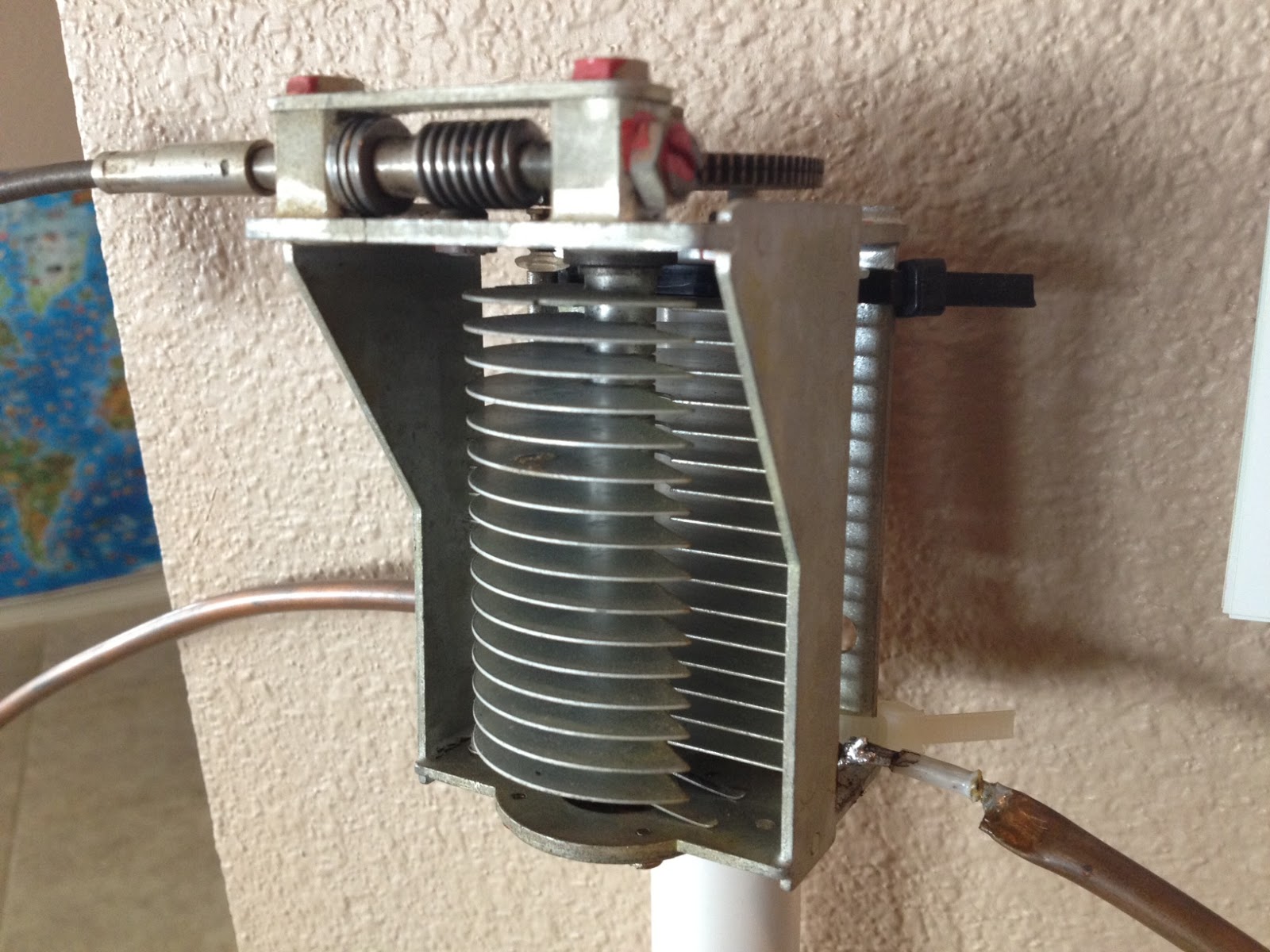
Once the main loop is constructed you’ll need to connect your capacitor to the two ends of the pipe at the top of the loop. Depending on the capacitor you may want to solder tags to the ends of the loop so they will be easier to attach. Copper pipe is a great conductor of heat and takes a lot to heat up and solder while it is not advisable to apply the same amount of heat to your capacitor.
It is also a good idea to attach the capacitor to a solid support so that the connections are not under strain.
The main loop and the capacitor forms the resonant circuit of the magnetic loop antenna.

To couple the main loop to your transceiver and match the expected 50 Ohms impedance you can use one of two methods. Probably the easiest is to use is a loop of insulated wire 1/5 the circumference of the main loop. The smaller loop is placed at the bottom of the main loop and can be shifted around to provide the best match. If you have an antenna analyzer you’ll be able to set it to the desired frequency, tune the variable capacitor for resonance and then move the small matching loop around till you have achieved close to 1:1 SWR. If you don’t have an antenna analyzer you can tune the capacitor for the greatest received noise and then on low power tweak the capacitor and move the coupling loop around for best SWR. Do NOT touch the loop while it is transmitting, use a wood or plastic rod to make adjustments as there are high voltages and intense RF fields near the loop.
An alternative to the coupling loop is the gamma match. The shield of the coax feed cable is connected to the base of the main loop while the inner conductor is connected to a point approximately 1/5 of the circumference around the loop. Its a good idea to use stiff wire (large gauge) for the gamma match as it can be critical of the position and orientation and once you have it in the right position you won’t want to move it again.
It would be preferable to have the ability to remotely tune the loop. A motor with a reduction gear could be used to move the variable capacitor but because the point of resonance is very narrow there should be a way of slowing the motor down. A simple control circuit using variable pulse width modulation could be used to slow the motor down while still retaining enough torque to move the capacitor. Whatever method is used to move the capacitor it should be well insulated from the other components of the antenna. Several thousand volts are generated on the MLA and care should be taken to ensure they don’t find their way onto control leads and back into the shack. Control leads should also be wrapped around toriod inductors as they leave the near field of the antenna to reduce the possibility of RF travelling along them.
With a SWR bridge and microcontroller you could build a fully automatic tuner that swept through the range of the tuning capacitor when the SWR rose above a defined limit indicating that the transmit frequency had changed.
With a little creativity and knowledge you could have an impressive MLA the equal of multi-thousand dollar military style units.
Hopefully this has given you some ideas for constructing your own loop antenna. Regardless of if you go top-of-the-line and buy a vacuum variable or build for economy and QRP you’ll have a compact, useful and unique antenna.
DIY Magnetic Loop Antenna – Part 2
Part 1 of the DIY Magnetic Loop Antenna covered mostly theory and materials so now its time to move on to designing the magnetic loop antenna (MLA).
If you have priced a commercially made MLA you’ll see prices start at $400 and keep going up, and up. If they cost so much you would think they must be difficult to build or use expensive parts, right? Well, it is certainly possible to spend more and get a higher quality MLA but a low cost MLA will still work very well.
For the purposes of this article we’ll assume that you want to build a loop to cover the 20-10M bands. I’ll run through the calculations required to build the MLA.
The required information for the MLA calculator is:
- Length of the loop
- The conductor diameter
- Frequency/s of operation
- Input power to the antenna
- We don’t really know the best length of the loop at the moment so I’ll pick 9 feet circumference as a starting point (It’ll still fit in the trunk of my car)
- Since we seem to be having better luck with sunspots now I’d like to try 10M so we’ll start with 29 Mhz as the highest frequency we’ll use.
- I have some copper pipe left over from an ice-maker install, it is 1/4 (0.25) inch in diameter.
- Input power to the loop will be 100W.
 A peak voltage of 5181V will require a minimum spacing of 1.7 mm (peak voltage / breakdown voltage per mm) between the closest conductors in the capacitor. That would rule out an old air spaced variable capacitor from a vacuum tube radio but you could still use a wide spaced variable capacitor from an antenna matching unit or transmitter. A vacuum variable capacitor would be great (watch the minimum capacitance) or a home-made capacitor would also be fine provided you checked the breakdown voltage of the insulating material.


