Posts Tagged ‘home-brew’
 CW decoder – The Arduino
 This is arguably the simplest part of the project. As mentioned Budd Churchward had created a series of videos on how he wrote the Sketch, created a PCB and published his code. (Budd’s Sketch is available here)
CW decoder – The electronics

CW decoder – The electronics
CW decoder – Introduction
 If you do follow me on twitter (and if you don’t – you really should) you will have no doubt seen my recent tweets about constructing a CW decoder. After a number of retweets, and favorites from other very interested hams – I did promise that I would collate all my knowledge into a blog posts and share the details with you all.
So, for those who have not been following me on twitter – here is the sales pitch. I recently started looking at some projects that I could get my Arduino Uno involved in with the radio hobby. I have a number of reasons why I want to combine radio, Arduino and some electronics – more about this later.
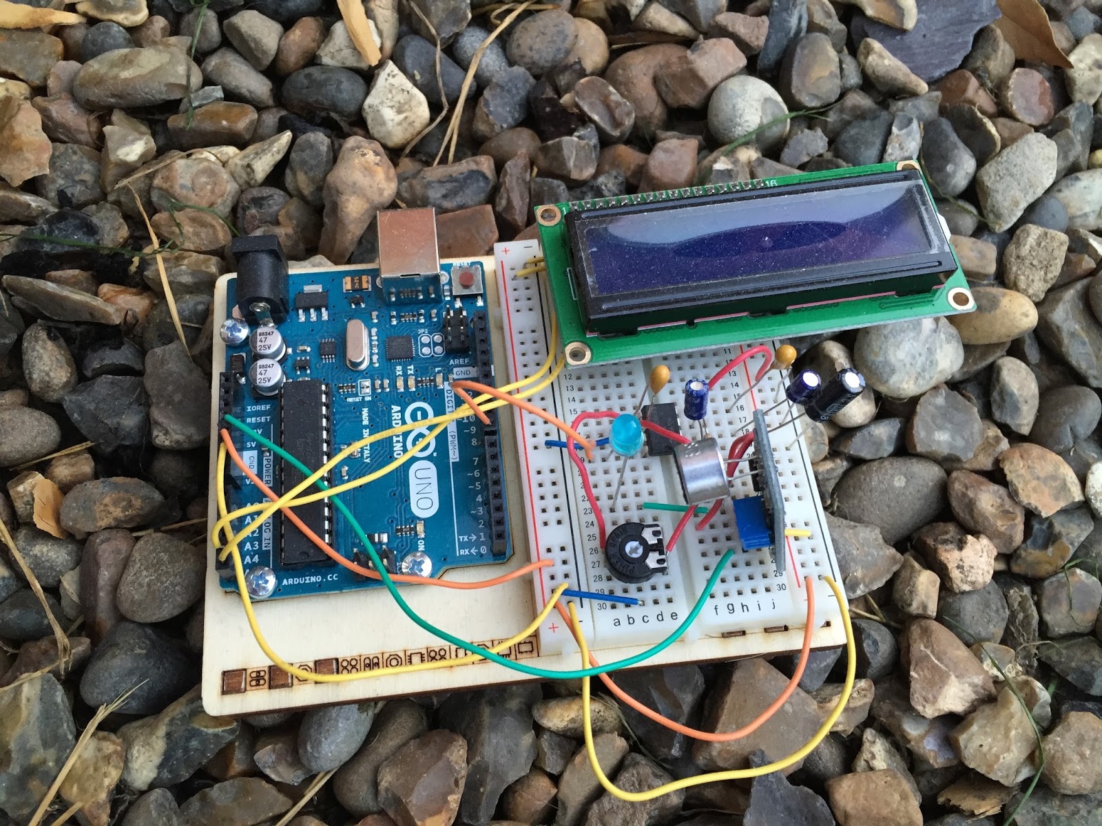
I stumbled across a video on YouTube where Budd Churchward showed his Arduino copying and decoding CW straight off the HF band and at a reasonably high speed. I ventured further and wanted to know what electronics Budd was using to achieve this excellent little project.
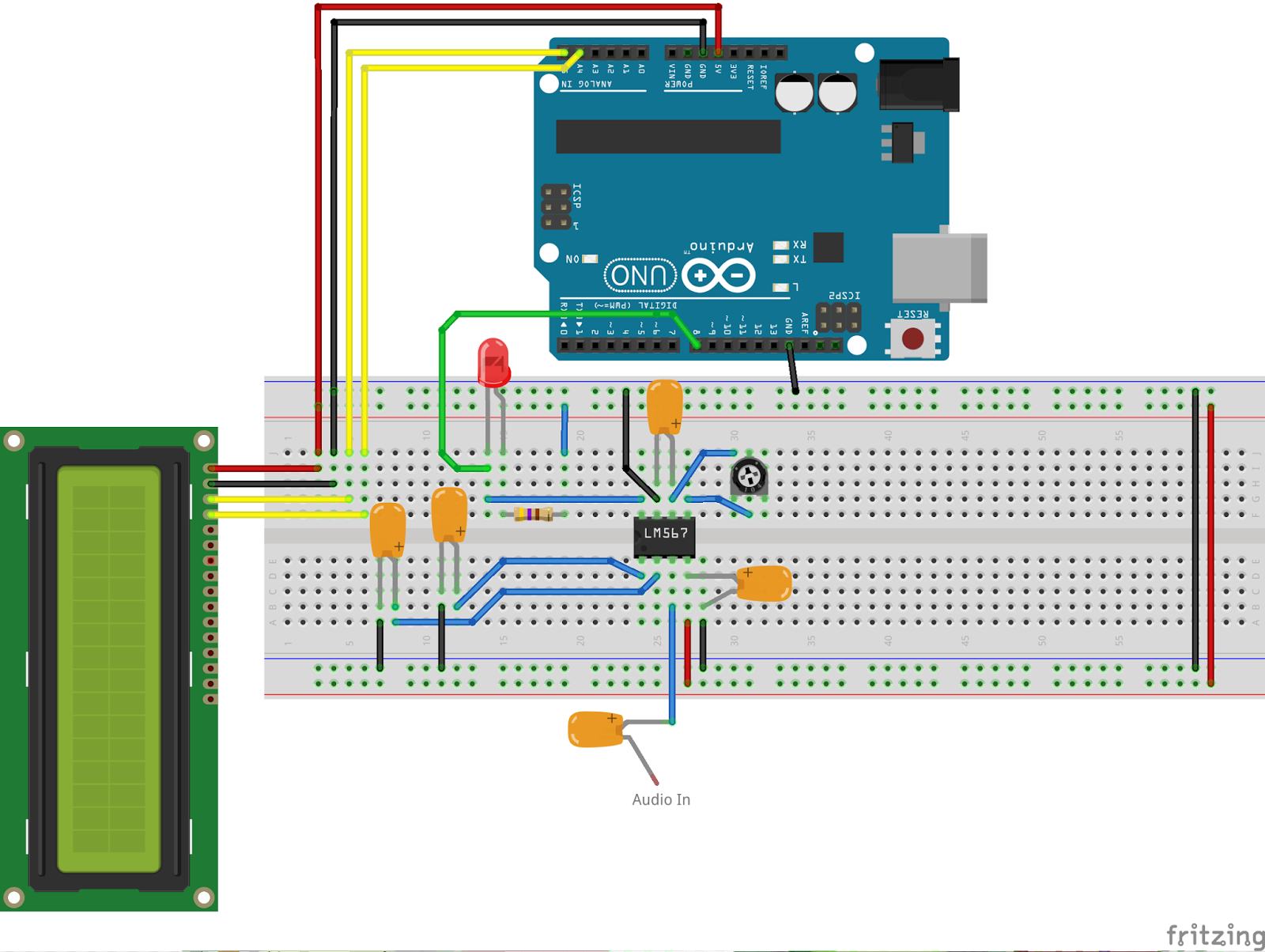
I used the limited shared knowledge and discovered that the electronics is basally a LM567 – Tone decoder chip that (I have since discovered the chip is used in the ARRL book for Arduino Projects) I discovered takes an audio input and converts this to a HIGH / LOW output suitable for the Arduino to use as a signal for decoding.
Finding a suitable project for the LM567 and trying to work out how fellow constructors had configured their LM567s was not an easy task. This did indeed take quite a lot of chasing and head scratching. I will go into more technical detail on the next post – but for the reason why I wanted to complete this ? very simple. I w
ant to create a project that would “inspire” young electronically minded students that might have an interest in radio – (i.e the morse code) some coding experience and some construction / electronic interest. This project covers all 3 areas, and only lightly covers each subject area.
In the next post – I show the LM567, the schematic and give you the list of parts required.
CW decoder – Introduction
If you do follow me on twitter (and if you don’t – you really should) you will have no doubt seen my recent tweets about constructing a CW decoder. After a number of retweets, and favorites from other very interested hams – I did promise that I would collate all my knowledge into a blog posts and share the details with you all.
So, for those who have not been following me on twitter – here is the sales pitch. I recently started looking at some projects that I could get my Arduino Uno involved in with the radio hobby. I have a number of reasons why I want to combine radio, Arduino and some electronics – more about this later.
I stumbled across a video on YouTube where Budd Churchward showed his Arduino copying and decoding CW straight off the HF band and at a reasonably high speed. I ventured further and wanted to know what electronics Budd was using to achieve this excellent little project.
I used the limited shared knowledge and discovered that the electronics is basally a LM567 – Tone decoder chip that (I have since discovered the chip is used in the ARRL book for Arduino Projects) I discovered takes an audio input and converts this to a HIGH / LOW output suitable for the Arduino to use as a signal for decoding.
Finding a suitable project for the LM567 and trying to work out how fellow constructors had configured their LM567s was not an easy task. This did indeed take quite a lot of chasing and head scratching. I will go into more technical detail on the next post – but for the reason why I wanted to complete this ? very simple. I w
ant to create a project that would “inspire” young electronically minded students that might have an interest in radio – (i.e the morse code) some coding experience and some construction / electronic interest. This project covers all 3 areas, and only lightly covers each subject area.
In the next post – I show the LM567, the schematic and give you the list of parts required.
Its quiet. WSPR quiet
If you ever needed proof that QRP is good fun and very rewarding, look no further than my latest project. I just (today) finished building the QRP Labs Ultimate 3 kit. This kit is amazing and I’ve ordered mine with the 20m BPF as thats the lowest band my home Antenna will go to.
In its current configuration my kit only pumps out 200mW and I left it running while i went out to a party with the family. On my return I was staggered by the reach on the little kit. The longest distance it was heard was a staggering 6408Km ! all that way with just 200mW of RF..
Here is a map I’ve downloaded of the plots :
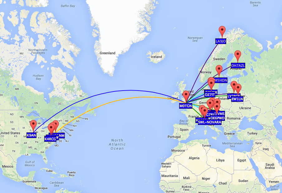
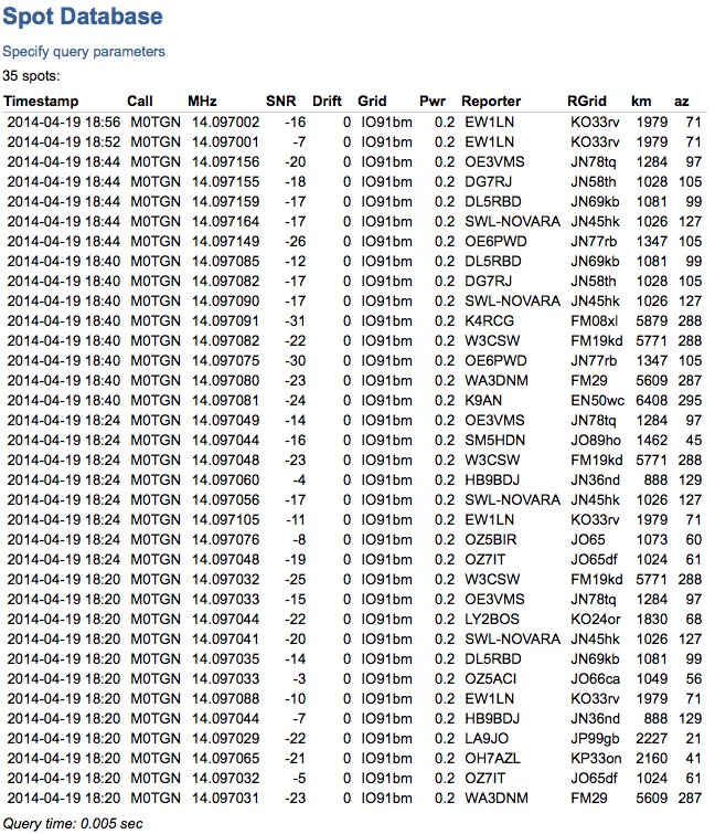
and a list of the stations that heard it. You will notice some frequency fluctuation. I have to box the kit up and think about some stabilisation on the DDS. but hey for its first outing – I’m very happy !
New toys.
Its been some time since I bought myself any new toys but the two purchases I have made really are for when I am QRP with my go pack.
 Firstly I have changed the rucksack I use. The previous pack was excellent initially but I quickly understood its limitations and when full of kit I realised that everything essentially falls down to the bottom and makes the pack really quite uncomfortable to carry.
After much research I noticed a few reviews of the 5.11 rush series. They have 3 packs designed and named the 12, 24 & 72. I decided to go for the 5.11 Rush 24 which has a capacity of 34 litres which is pretty much the same as the previous pack, but this one has may compartments and sections to store the kit.
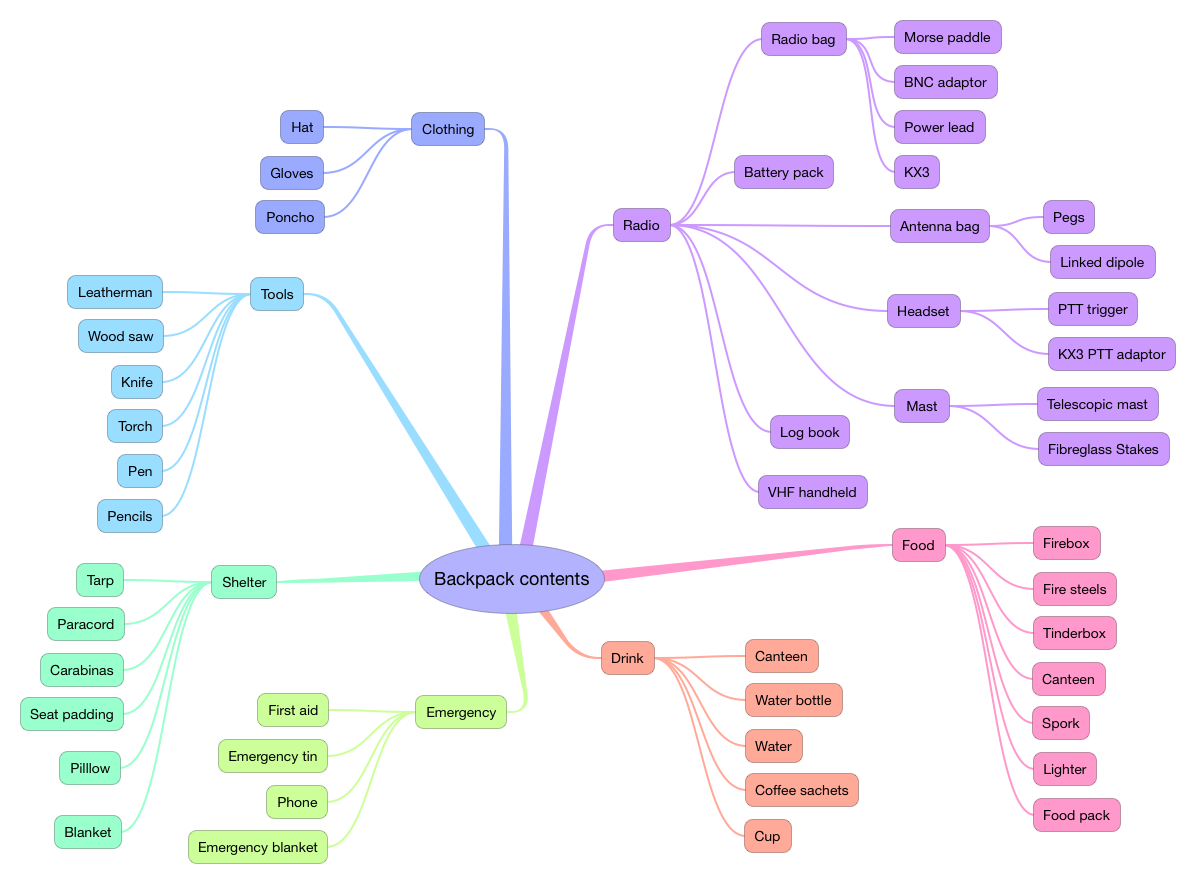
One big advantage of this pack is the MOLLE (Modular Lightweight Load-carrying Equipment) strapping that the back pack has all over it. Meaning that you can purchase extra modular pouches, cases and attachments to the outside of the pack. So far I have managed to pack the water bottles, mast and VX8 hand-held radio to the outside of the pack with specifically designed pouches. This of course leaves the inside completely free to carry the essentials. Click here for more info on the 5.11 Rush 24
With the repacking and organising of the new case I did document (stock check I suppose) the contents of the pack so I know exactly what I am carrying – and can adjust with ease what I want to carry. I documented it in the form of a mind map, and I’m sure there are bits that I have missed off – feel free to comment.
As I was packing the case I also really decided it was time to change the battery power I have been carrying for some time to a new light weight alternative.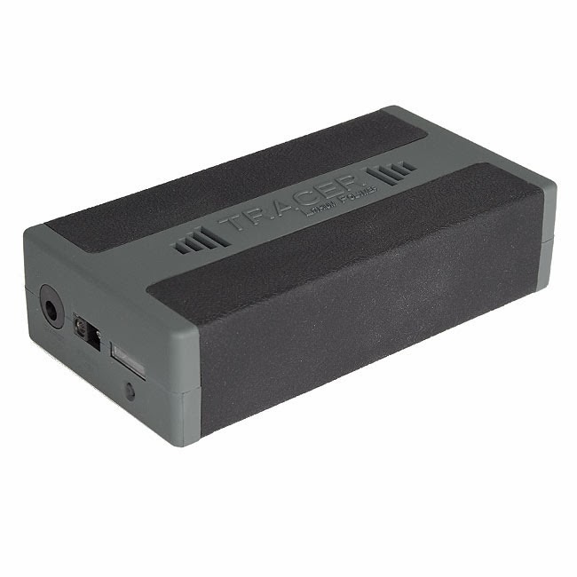
Weighing in at a quarter of the weight of the SLA, I have opted for a Lithium Polymer pack designed by Debam. Its not cheap but well worth the investment when it radically reduces the weight of the pack. The battery is 8Ah and comes with its own fuel gauge, choices of charging adaptors and comes in its own case.
The pack is also smaller than the old SLA, but 1 disadvantage is that I cannot use the Solar panel with this pack as I doesn’t being trickle charged. So the SLA pack complete with Watts Up meter will remain intact and live in the boot of the car. Click here for the details of the battery.


