Posts Tagged ‘home-brew’
 Arduino Morse Tutor – Update
Its quite humbling really. Ive had this blog now for a number of years. I’ve always had a bit of a love/hate relationship with it. I love the concept of sharing my experiences, failures and successes with who ever stumbles across the blog. But mostly only a couple of entries get found and commented on. Namely my MQ26SR antenna posts are the most popular entries on this blog and I get about 1 email a month asking very specific questions.
That all changed this week. With the addition of my latest Arduino project. All of a sudden and quite literally overnight – the traffic to this blog skyrocketed. My inbox was awash of emails asking questions, my twitter feed was stacked with retweets and favorites of this circuit. I seem to have struck a chord with many folks who, like me, were looking for a Morse Tutor, but don’t want to sit in front of a PC all day.
I’ve had some really wonderful feedback. I have been offered Crowd funding, beta testers and asked if I can supply more information. So I hope this entry can help with my plans for my Morse Tutor version 2, So here are some headlines for you all.
- I am making a kit. I have this in hand and a PCB design is on the screen right now.
- This will be launched as soon as I have figured out some minor gremlins.
- There will be added functionality. And some really cool features too – watch this space.
- The Sketch I have created so far is only a fraction of what is on offer. (plus also a lot of fixes have been included in the Version 2 build)
- Below are 2 drawings – 1 Schematic, 1 Breadboard. This will support Version 1.01 of the code.
Version 2 will include an Audio Amp, an SD card and proper switching logic (either a rotary encoder, or latch chip) four new modes of training and all ready as either a pre assembled kit or kit of parts for you to build & box yourself. And trust me on this, it wont be expensive either.


Arduino Morse Tutor

In a recent conversation with my good friend Lewis, we started discussing Morse code, training and the old equipment that was used to educate and teach the code to newcomers. In particular we discussed the old Datong D70 practice oscillators. Lewis carried on the tell me that his Datong like so many others started sending odd illegal characters and essentially rendered the kit useless. Of course you could whip of the lid and replace the logic chips, but I thought of recreating the Datong functionality in a new Arduino sketch.
So here is a breakdown of what the Datong offered:
- Either Mixed, letter or number combinations
- Groups of 5 characters
- Variable speed ( up to 37.5 word per minute)
- Variable character spacing (up to 4 seconds)
The Datong also allowed you to connect a telegraph key, and your headphones. But for now I will focus on the code generation element of the project.
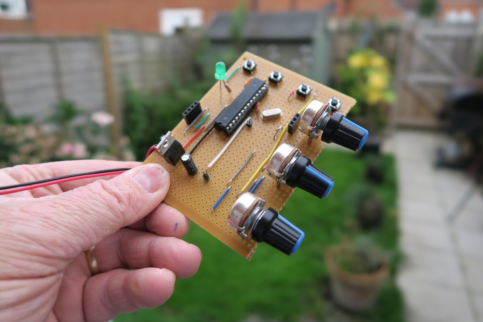
The finished project has just a handful of components and can easily be created on a breadboard, or indeed if you have an old broken Datong you can reuse the box and panel to really replicate the old kit. The complete project includes 3 variable resistors (1K LIN) for Character speed, gap and volume. It also needs a 3 way switch to select the mode.
The Arduino I’m using is the UNO. Arguably the most popular Arduino on the market, but I have also tried the sketch on a Nano and it works fine – just some customisation of pin assignments is all that is needed.
On start up the Arduino checks to see which switch is LOW – it also saves the current mode and checks if the saved mode is the same as the current selected switch. If this is different, then the Arduino has had a change in the mode selection and resets.
When generating the tones, the Arduino randomly selects a character from an array. With that chosen letter – it calls a function and plays the corresponding tone functions. 2 functions exist as a DIT and a DAH.
The rest of the functions are dedicated to allowing the speed and gap to alter and also displaying the results on the LCD panel (completely optional).
Here is a short video of the kit working, and a link to the source code.
Arduino Morse Tutor
In a recent conversation with my good friend Lewis, we started discussing Morse code, training and the old equipment that was used to educate and teach the code to newcomers. In particular we discussed the old Datong D70 practice oscillators. Lewis carried on the tell me that his Datong like so many others started sending odd illegal characters and essentially rendered the kit useless. Of course you could whip of the lid and replace the logic chips, but I thought of recreating the Datong functionality in a new Arduino sketch.
So here is a breakdown of what the Datong offered:
- Either Mixed, letter or number combinations
- Groups of 5 characters
- Variable speed ( up to 37.5 word per minute)
- Variable character spacing (up to 4 seconds)
The Datong also allowed you to connect a telegraph key, and your headphones. But for now I will focus on the code generation element of the project.
The finished project has just a handful of components and can easily be created on a breadboard, or indeed if you have an old broken Datong you can reuse the box and panel to really replicate the old kit. The complete project includes 3 variable resistors (1K LIN) for Character speed, gap and volume. It also needs a 3 way switch to select the mode.
The Arduino I’m using is the UNO. Arguably the most popular Arduino on the market, but I have also tried the sketch on a Nano and it works fine – just some customisation of pin assignments is all that is needed.
On start up the Arduino checks to see which switch is LOW – it also saves the current mode and checks if the saved mode is the same as the current selected switch. If this is different, then the Arduino has had a change in the mode selection and resets.
When generating the tones, the Arduino randomly selects a character from an array. With that chosen letter – it calls a function and plays the corresponding tone functions. 2 functions exist as a DIT and a DAH.
The rest of the functions are dedicated to allowing the speed and gap to alter and also displaying the results on the LCD panel (completely optional).
Here is a short video of the kit working, and a link to the source code.
Acorn II SDR Kit
This year at the RSGB convention we will be running a buildathon based upon the same format of the other successful build events in the past – this is an excellent time to attract a new audience to our events.
This year however we are using a new kit. The Acorn II kit developed by Kanga Products and M0XPD, is a Software Defined Radio kit that runs on the SSB portion of 40m. But the kit can also be configured to run on any HF band – assuming you have a Band pass filter & a suitable Local Oscillator. The kit has been developed to allow you to pipe in an external Local Oscillator and allow you to connect Band pass filters for other HF bands.
The kit was developed to run with the M0XPD Si5351A Arduino shield, which allows you to use the Arduino as a VFO. And can plug straight into the radio as a local oscillator
Using just a stereo line in on a sound card, and some widely available SDR software (Such as HDSDR), you can get great results from little financial outlay. It is indeed a great introduction into SDR.
I built one of the prototypes here is a video of the build. I will cover configuration & set up in a forthcoming video – perhaps when I have access to a good 40m antenna
Arduino CW decoder – Conclusion
1. Line in or Microphone input
2. Easy to read display – all boxed neatly
3. An LED that shows the Zero beat
4. Easily accessible Reset Switch
5. Powered from a 12v supply.
I did want to create a usable PCB, something that could be used by a student or someone wanting to build the kit. So using the Fritzing application I set about laying out a circuit board.

This was my very first attempt at creating a PCB , so nerves were a wee bit on the tense side. I also wanted to box the project, so my rationale was to find a box first to work out the physical dimensions of the finished project.
As with the Vero Version – I created a layout that would fit on top of the UNO.
After submitting the design, and waiting a week I managed to get hold of 3 boards. They looked awesome. All white and exactly how I laid them out.
I did make 2 small errors on these boards. The first issue was sitting the capacitors a bit too close to the LM567 IC. That is an easy fix for the next version. But the 2nd and more serious issue is I forgot to ground 2 caps. They were floating and in parallel. I did fix this by attaching a wire to ground from one of the caps. That solved the issue, and I have already corrected the fault for the next batch of boards.
2 further observations of the boards & the project as a whole have highlighted 2 further improvements to the project. The location of the pins for the display / reset switch and audio OUT should be on the other side of the board. That would make a far better layout. Also adding in an audio oscillator / switch & plug to insert a key on the oscillator – then feed the output to the Arduino would immediately mean this kit could be used as a practice oscillator too. – that would show the letters as you transmit them out.
So here is a review of the project so far, and what I intend to do with the project going forward.
Arduino CW decoder – Conclusion
1. Line in or Microphone input
2. Easy to read display – all boxed neatly
3. An LED that shows the Zero beat
4. Easily accessible Reset Switch
5. Powered from a 12v supply.
I did want to create a usable PCB, something that could be used by a student or someone wanting to build the kit. So using the Fritzing application I set about laying out a circuit board.
This was my very first attempt at creating a PCB , so nerves were a wee bit on the tense side. I also wanted to box the project, so my rationale was to find a box first to work out the physical dimensions of the finished project.
As with the Vero Version – I created a layout that would fit on top of the UNO.
After submitting the design, and waiting a week I managed to get hold of 3 boards. They looked awesome. All white and exactly how I laid them out.
I did make 2 small errors on these boards. The first issue was sitting the capacitors a bit too close to the LM567 IC. That is an easy fix for the next version. But the 2nd and more serious issue is I forgot to ground 2 caps. They were floating and in parallel. I did fix this by attaching a wire to ground from one of the caps. That solved the issue, and I have already corrected the fault for the next batch of boards.
2 further observations of the boards & the project as a whole have highlighted 2 further improvements to the project. The location of the pins for the display / reset switch and audio OUT should be on the other side of the board. That would make a far better layout. Also adding in an audio oscillator / switch & plug to insert a key on the oscillator – then feed the output to the Arduino would immediately mean this kit could be used as a practice oscillator too. – that would show the letters as you transmit them out.
So here is a review of the project so far, and what I intend to do with the project going forward.


