Posts Tagged ‘home-brew’
 DIY Magnetic Loop Antenna – Part 1
Do you live in a neighborhood with a restrictive antenna policy and despair of having a useful HF antenna?
Can you solder or know someone who can?
A magnetic loop antenna may be the answer and they are not as difficult to build as you might think. Like getting on the air for the first time or taking your license exam there is a certain amount of uncertainty when you first approach magnetic loop antennas, there are a few new ideas to grasp. However, thanks to other hams like Steve AA5TB there are tried and tested designs, calculators & building methods that are known to work and that you can follow.
 At the heart of every radio and MLA (Magnetic Loop Antenna) is the resonant circuit. The combination of an inductor (a wire has inductance, but a coil of wire has more) and a capacitor (two conductors separated by an insulator) in a circuit will resonate or ‘ring’ at a certain frequency. Sound vibrations at a certain frequency can cause a piano string to vibrate in sympathy and a vibration of the correct radio frequency will cause a resonant circuit to electrically vibrate in sympathy.
Since there is no such thing as a free lunch, the sacrifice you make with a MLA is that it needs to be re-tuned whenever you change frequency on your transceiver. The frequency range over which it is resonant is very small, typically only a few hundred kilohertz at the most.
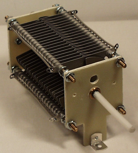
The materials you can get your hands on is going to decide the capabilities of your MLA. Ideally you’ll have a loop made from a conductor with very low resistance (usually copper) and a capacitor that can handle high voltages. A variable capacitor is required if you want to use your antenna on multiple frequencies but you can use or make a fixed capacitor if you operate on one frequency, for Eg PSK31.
A MLA calculator like the Excel spreadsheet from Steve AA5TB or this web page from 66pacific.com will help you to decide what size components you’ll need to make your antenna.
The four pieces of information required are:
- What frequency or frequencies do you wish to transmit on?
- How large do you want the loop to be (It should have a circumference less than 10% of the design frequency wavelength, both calculators help you figure this out)
- The diameter of your conductor (Three quarter inch (0.75 inch) copper pipe is a good start)
- How much power you want to use (The voltage across the capacitor is proportional to the input power to the MLA)
 A MLA of a certain circumference will be more or less efficient based on the frequency you transmit at. It is worth changing the loop size in the calculator to get the best efficiency possible in your favorite band.
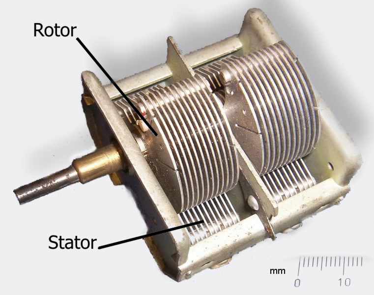
Now I understand – Phase Locked Loops
Every now and then I come across great books or videos that explain a concept in such a way that it becomes immediately obvious what is going on. I’m a great believer in learning by demonstration or even better, learning by doing.
I came across another explanatory video recently that I thought was too good to keep to myself. It covers a topic that was a complete mystery to me: Phase Locked Loops. We utilize them in almost every modern transmitter and receiver yet most people I have talked to view them as a black box that, fortunately, does its job well and usually without interruption.
The video below does a good job on opening the black box and showing just what makes phase locked loops … well, lock.
Heathkit’s first amateur transmitter – Heathkit AT-1
The Heathkit AT-1 represents the commercial embodiment of the simple Master Oscillator Power Amplifier (MOPA) transmitter using a crystal controlled 6AG7 oscillator plus a 6L6 final output tube.
Although it was possible to design and build a simpler transmitter, the goals of output power and stability could become mutually exclusive when trying to operate with only one tube. For a novice class license holder of 1951 the Heathkit AT-1 represented a solid performing rig that would be relatively easy to construct and operate.
The Novice remained the primary entry license until the Morse code requirement was eliminated for Technician licenses in 1990. On HF it permitted code transmissions only, with a maximum power of 75 watts, (input to the transmitter’s final amplifier stage) on limited segments of the 80, 40 and 15 meter bands.
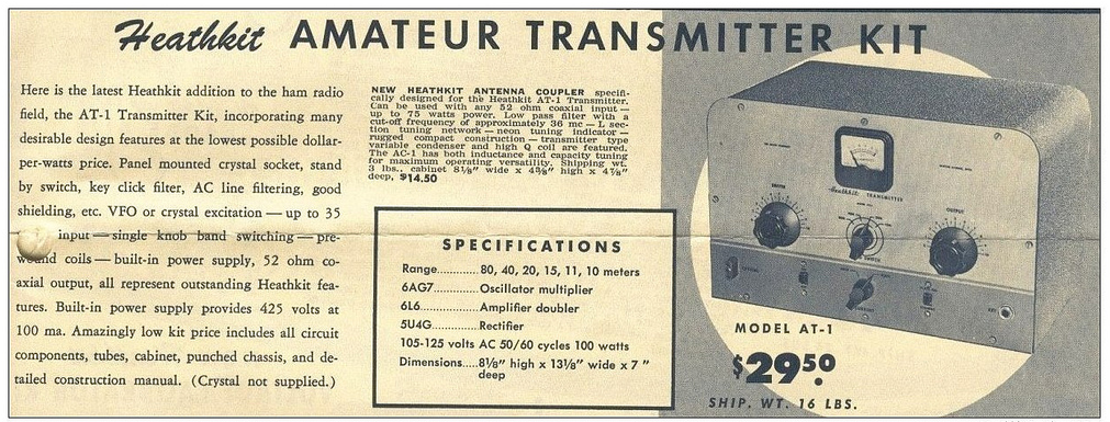 |
| For $29.50 and the loan of a few tools you could get some use out of that new novice license |
The earlier MOPA circuit from the ARRL handbook of 1941 below shows a layout remarkably similar to the circuit of the AT-1 although it is designed for plug in coils rather than the band-switching arrangement of the later Heathkit transmitter.
| MOPA transmitter using a 6L6 and an 807 as the power amplifier (ARRL Handbook 1941) |
For a little added complexity MOPA transmitters generally offered better stability of frequency and keying waveform than single tube crystal controlled or self exited rigs. The straight forward design of the AT-1 should have looked familiar to novice class hams after studying the ARRL handbook or other radio publications.
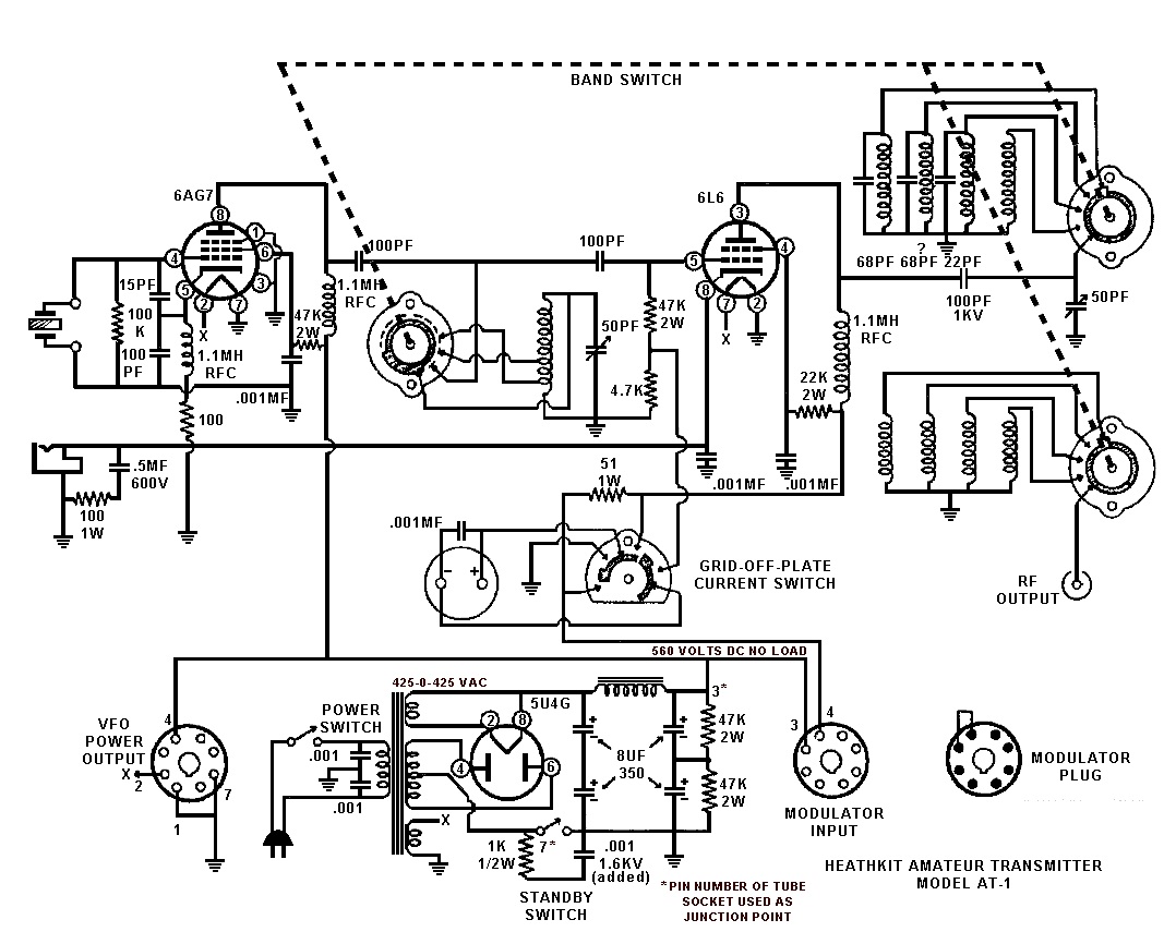 |
| Heathkit AT-1 Circuit diagram showing band-switching arrangement and link coupled output |
Once the novice had upgraded his license the AT-1 could be expanded by the addition of the Heathkit VF-1 variable frequency oscillator to allow transmission on any frequency within the allowed band.
 |
| The Heathkit VF-1 Variable Frequency Oscillator |
The VF-1 covered 160-80-40-20-15-11-10 meters and used an OA2 voltage regulator tube to provide a stable voltage for the oscillator. Ceramic coil forms, solid construction and high quality components were used to help increase stability.
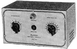 |
| The Heathkit AC-1 Antenna Coupler. Designed to attach to a single wire by the insulated post on the front panel. |
 |
| Heathkit AC-1 Antenna Coupler circuit diagram |
Although Heathkit did not produce a AM modulator for the AC-1 there is provision for modulator connection on the rear panel. The earlier ARRL manuals have several suitable circuits for modulators that would work with the AC-1. Most functioned by driving a modulation transformer with the output from an audio power amplifier. The secondary of the modulation transformer would be carrying the DC plate supply for the power amplifier tube plus or minus the instantaneous voltage of the audio waveform. By changing the plate voltage to the final amplifier tube the radio frequency output would be controlled by the amplified audio frequency resulting in amplitude modulation.


