Posts Tagged ‘Electronics’
 PIXIE 2 QRP Transceiver build
HackRF on Sky Loop Antenna and Talented Balun
Arduino Frequency Display For Kenwood TS-520S HF Ham Radio PART 5
This is PART 5 of the project “Arduino Frequency Display For a Kenwood TS-520S HF Ham Radio”.
Steve Leander from www.kv6o.com picked up where I left off in part 4 and completed the project.
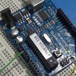
He designed a complete DG5 emulator Arduino shield starting from the prototype circuit and adding 5v power regulation and support of a LCD display. Steve completed the software and shared the BOM list, parts purchase links, circuit drawings and his code (here). Thank you Steve for finishing the DG5 emulator board and Arduino code!
Many thanks also to Larry from YouTube Channel “RadioHamGuy” for helping with testing.
Larry makes many great videos about ham and CB radios.
Links to all parts: (PART 1), (PART 2), (PART 3), (PART 4), (PART 5)
.
Photo Gallery
CLICK PHOTO for gallery view and click a SECOND time for hi-resolution image. Click thumbnails on lower right and lower left of gallery to navigate gallery photos.


Arduino Frequency Display For Kenwood TS-520S HF Ham Radio PART 4
This is PART 4a (there is a part 4b below) of the project “Arduino Frequency Display For a Kenwood TS-520S HF Ham Radio”. This part covers switching to a new front end circuit as seen used by the DFD2 frequency counter from “Almost All Digital Electronics”. Their website is http://aade.com/DFD2inst/DFD2inst.htm
All parts: (PART 4), (PART 3), (PART 2), (PART 1)
(PART 4A)
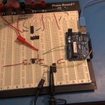
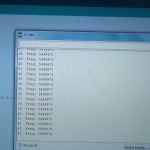
This is PART 4b of the project “Arduino Frequency Display For a Kenwood TS-520S HF Ham Radio”. This part covers testing the circuit and frequency counter software when connected to the Kenwood radio but still on a bread board. The final display is not ready so in this video I simply push the frequence counts to the laptop.
(PART 4B)
Here is the datasheet for the PLL chip I used in (PART 4). Other datasheets can be found in (PART 1).
74HC4046 Phase-Locked Loop with VCO (PDF)
Arduino Frequency Display for Kenwood TS-520S HF ham radio PART 3
This is PART 3 of the project “Arduino Frequency Display For a Kenwood TS-520S HF Ham Radio”. This part covers 0.9 volt 38 MHz signal amplified into Schmitt triggered NAND gate for cleanup before going to a divide by 8 ripple counter chip then finally being cleanly counted by the Arduino using multiply by 8 math function to restore counts to 38 MHz. All parts: (PART 4), (PART 3), (PART 2), (PART 1)
Thanks for joining!
Arduino Frequency Display For Kenwood TS-520S HF Ham Radio PART 2
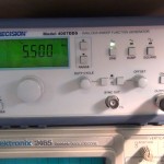
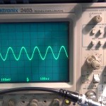
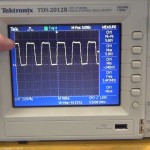
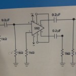
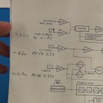
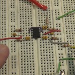
This is (PART 2A & 2B) of the project “Arduino Frequency Display For a Kenwood TS-520S HF Ham Radio”. This part covers small signal amplification of a 0.2 volt peak-to-peak 5.5 MHz signal into Schmitt triggered NAND gate for cleanup before being cleanly counted by the Arduino. All parts: (PART 4), (PART 3), (PART 2), (PART 1)
(PART 2A)
(PART 2B)
Here are the datasheets for the two chips I used in (PART 2)
74HCT132 Quad 2-input NAND Schmitt trigger (PDF)
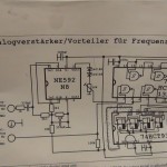
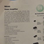
NE592 video Amplifier (PDF)
Thanks for joining!
Photo Gallery
CLICK PHOTO for gallery view and click a SECOND time for hi-resolution image. Click thumbnails on lower right and lower left of gallery to navigate gallery photos.
Thanks for joining!
Intermediate is go

We have started another intermediate class both in class and distance learning. This course is primarily run on Edmodo. We have run a couple of classes on Edmodo and we think we have the concept correct now. So we have our weekly quizzes set and our 3 week homework assignments all loaded and ready to go.
In class students are also welcomed to join the distance learning students so missing a lesson is no longer such an issue.
Over the coming weeks I will be creating some companion videos showcasing the practical elements of our in lesson activities.
So far we have 5 in class and around 30 distance learning joining us for the next 10 weeks.


