Posts Tagged ‘amateurradio.com’
 It’s the little things that make life worthwhile
In the day to day, sometimes it's easy to forget the little things that make life worthwhile.
1) Like that yesterday was my daughter Cara's 13th birthday - she's officially a teenager now!

3) That while I was eating my chicken corn chowder in my Jeep, I managed to work DL4ISX in Germany (with some difficulty due to QSB) and HF37SONDA in Poland (who was super loud).
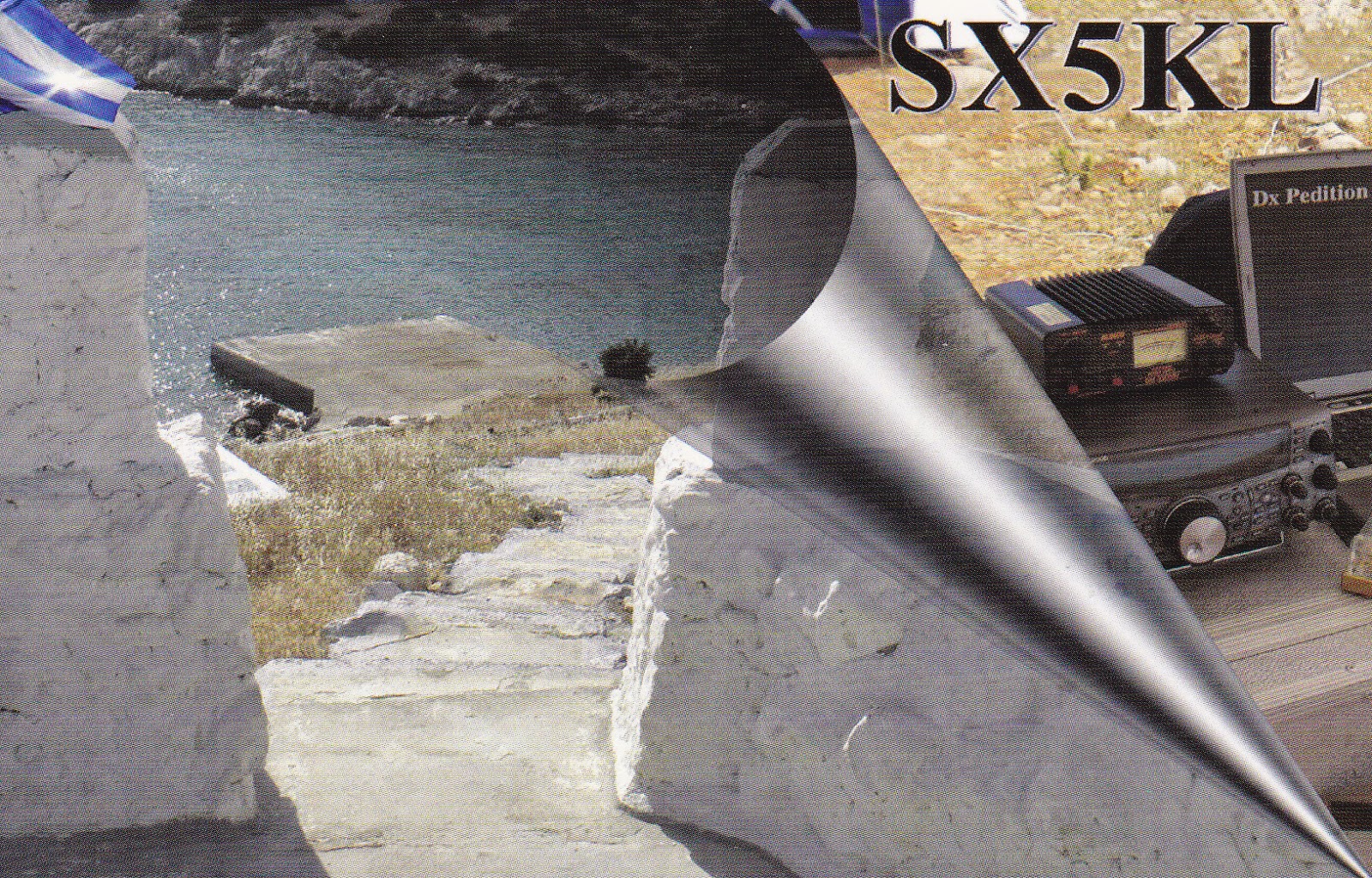
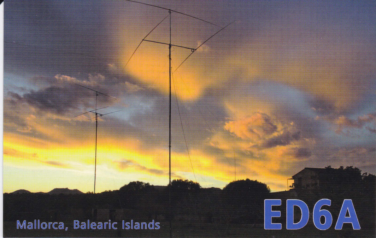
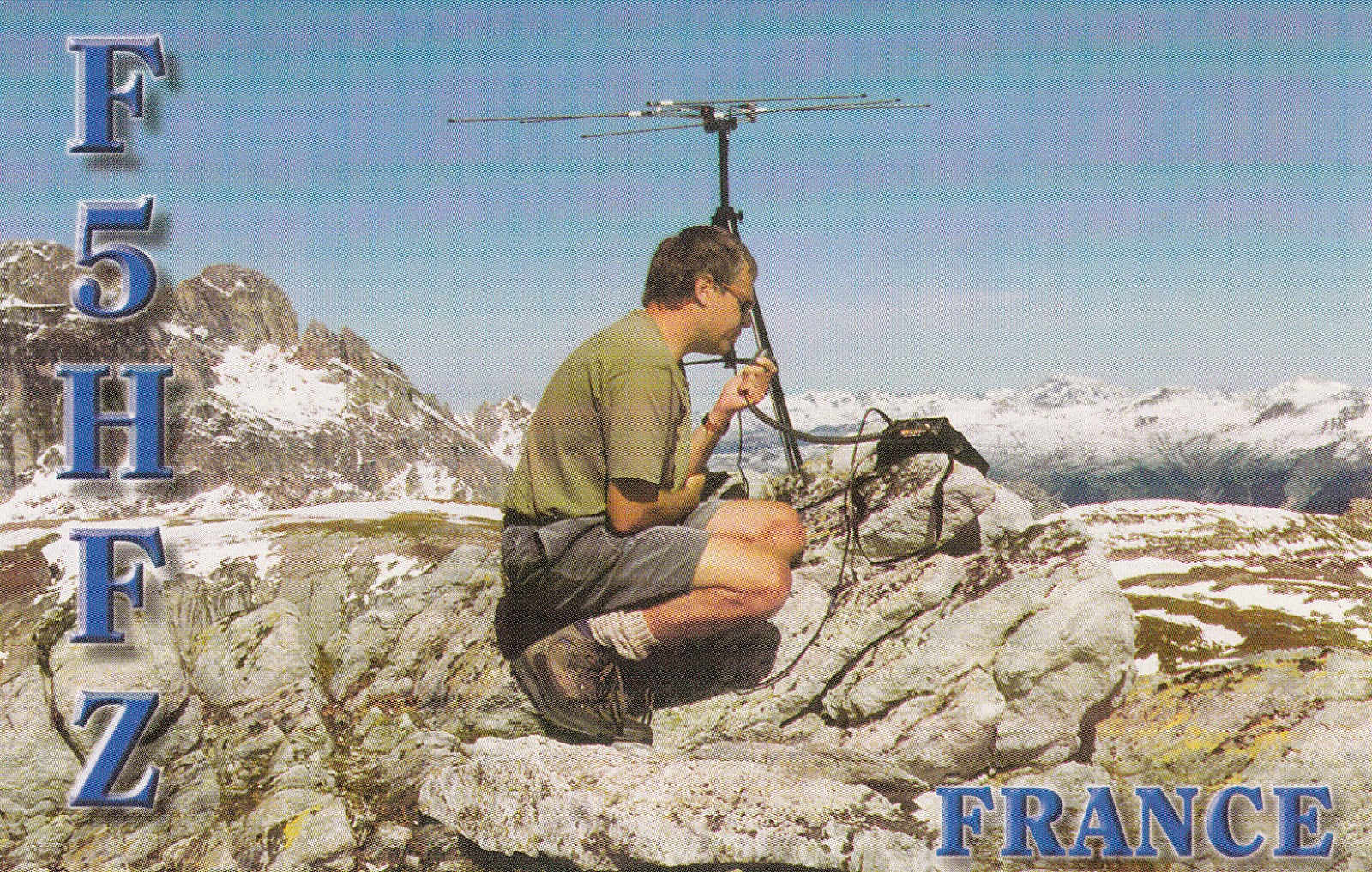
4) That I came home to a packet of QSL cards from the Bureau, including:


Yeah, it's the little things in life that are the absolute best!
72 de Larry W2LJ
QRP - When you care to send the very least!
1) Like that yesterday was my daughter Cara's 13th birthday - she's officially a teenager now!
Did I mention she DETESTS having her picture taken and that she was ready to kill me when I snapped this one at Lake George this Summer?
2) Like that today they served chicken corn chowder in the cafeteria at work today - one of my all time favorite soups.
3) That while I was eating my chicken corn chowder in my Jeep, I managed to work DL4ISX in Germany (with some difficulty due to QSB) and HF37SONDA in Poland (who was super loud).
4) That I came home to a packet of QSL cards from the Bureau, including:
Yeah, it's the little things in life that are the absolute best!
72 de Larry W2LJ
QRP - When you care to send the very least!
Excited

Marv K2VHW and I, under the auspices of the South Plainfield Amateur Radio Club, will be teaching a course for those in the greater Central New Jersey area who want to earn a Technician class license.
Here's the flier that Marv designed to advertise the class:
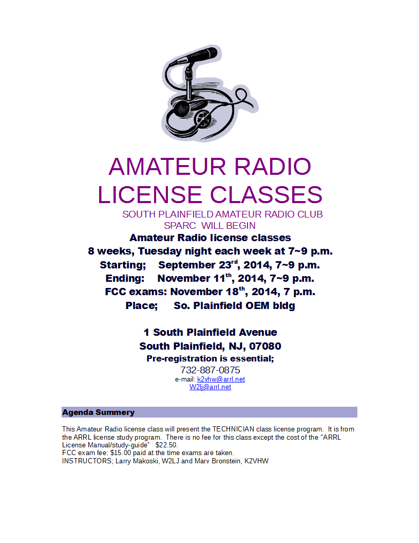
I'm excited, because so far we have eight potential students who have pre-registered. We have room for more, so if you're interested or know someone in the Central NJ area who might be interested, contact either Marv or myself. We would also ask that anyone who has pre-registered or wants to register, to please try to attend the next SPARC meeting on Wednesday, September 17th at 7:00 PM at the South Plainfield OEM building. At that time, we will be taking count and placing a group order for license manuals for the class. Marv and I are both ARRL Registered Instructors, and a such we can apply for a group rate for the manuals.
72 de Larry W2LJ
QRP - When you care to send the very least!


Repairing a Kenwood TR9500, Part2 – TX working, SSB RX not
As I suspected the microphone amplifier Q1 in the Kenwood/Trio TR9500 was indeed faulty. The replacement arrived next day and within an hour I had successfully soldered in the new 2SC2240 transistor and it now had audio on transmit.
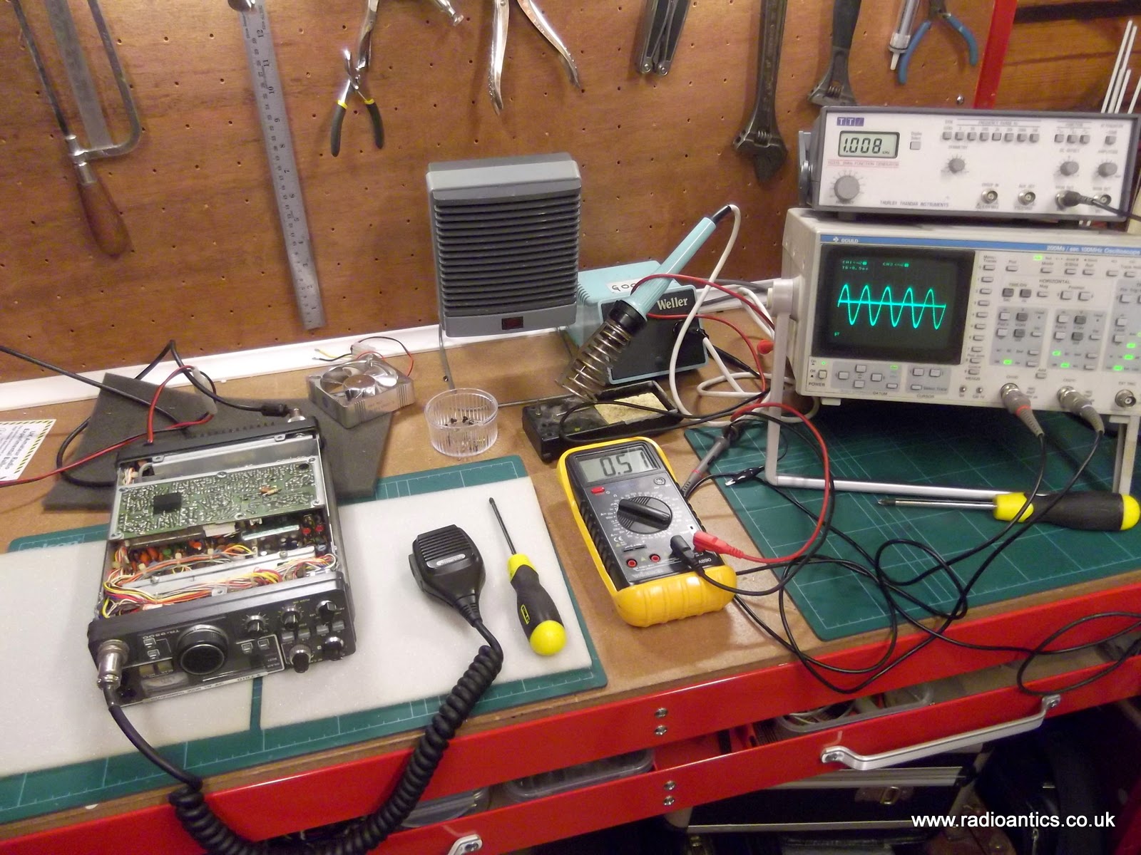
Transmitting into a dummy load and monitoring on my FT857-D the FM transmission was fine, the SSB was okay, perhaps slightly over driven. I suspected that maybe the previous owner might have twiddled something to compensate for a failing Q1.
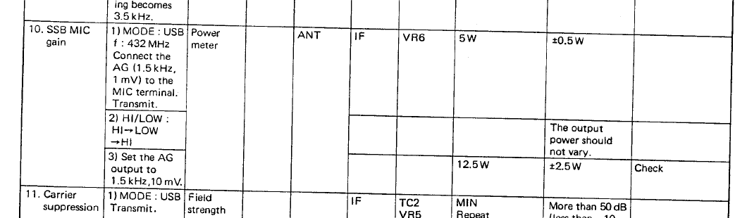
In the adjustments section of the service manual VR6 on the IF unit controls the SSB MIC gain. To check the settings it was a case of setting the transmitter to 432MHz and putting an audio frequency signals of 1.5kHz of amplitude 1mV and 10mV from my signal generator on to the microphone terminal, and observing the RF power output, which were the 5W and just over 10W as required. As this didn't need altering I left it alone and boxed it back up and returned it to the happy owner.
Last night was the RSGB 432MHz UKAC Contest and I was hoping to here it on the air, sadly I didn't. It now transpires that there maybe another issue with it, something I should have spotted.
I do remember something strange when doing the initial testing. Connected to a dummy load and in SSB mode the S-meter showed S9+ when in receive but with no audio, turning the RF gain control the meter dropped to S0 and normal white noise static could be heard. It received a SSB transmission from the FT857-D with no issue so I thought no more of it. Being over eager and not experienced with using different rigs I had mistakenly dismissed it and should really have read the operating manual more extensively.
The anomalous S9+ meter reading and no audio occured when the RF gain control was set to the maximum which is the normal recommended setting for operating, I'd simply turned the RF gain control to the minimum mitigating the issue.
Obviously the rigs owner had put the RF gain back to maximum and was now reporting it wasn't switching back to receive. In fact it is but nothing is being heard. Checking the service manual this morning and it appears there is an issue with the AGC circuit (description and block diagram below)

It seems the rig may well find itself back on the bench, however this repair could be more problematic!
As I mentioned it was the 432MHz UKAC last night and I had a decent night of search and pounce. Conditions were very strange, lots of fading and strangely some of the usual local operators were not heard. I was very pleased to catch some lift and made a couple of decent DX contacts in Northern Ireland, The Isle of Man, Northumberland as well as Essex and Cambridge.
Transmitting into a dummy load and monitoring on my FT857-D the FM transmission was fine, the SSB was okay, perhaps slightly over driven. I suspected that maybe the previous owner might have twiddled something to compensate for a failing Q1.
In the adjustments section of the service manual VR6 on the IF unit controls the SSB MIC gain. To check the settings it was a case of setting the transmitter to 432MHz and putting an audio frequency signals of 1.5kHz of amplitude 1mV and 10mV from my signal generator on to the microphone terminal, and observing the RF power output, which were the 5W and just over 10W as required. As this didn't need altering I left it alone and boxed it back up and returned it to the happy owner.
Last night was the RSGB 432MHz UKAC Contest and I was hoping to here it on the air, sadly I didn't. It now transpires that there maybe another issue with it, something I should have spotted.
I do remember something strange when doing the initial testing. Connected to a dummy load and in SSB mode the S-meter showed S9+ when in receive but with no audio, turning the RF gain control the meter dropped to S0 and normal white noise static could be heard. It received a SSB transmission from the FT857-D with no issue so I thought no more of it. Being over eager and not experienced with using different rigs I had mistakenly dismissed it and should really have read the operating manual more extensively.
The anomalous S9+ meter reading and no audio occured when the RF gain control was set to the maximum which is the normal recommended setting for operating, I'd simply turned the RF gain control to the minimum mitigating the issue.
Obviously the rigs owner had put the RF gain back to maximum and was now reporting it wasn't switching back to receive. In fact it is but nothing is being heard. Checking the service manual this morning and it appears there is an issue with the AGC circuit (description and block diagram below)
RECEIVER CIRCUIT
.... The signal is picked up from the last stage of the IF amplifier (Q23), then detected and amplified to generate the AGC voltage. The AGC time constant is automatically set according to the mode : FAST for CW; SLOW for SSB. The AGC voltage is applied to IF amplifiers Q21, Q22 and Q23 (3SK73(GR)) and RF amplifier Q51. It is also used to drive the S meter.
It seems the rig may well find itself back on the bench, however this repair could be more problematic!
As I mentioned it was the 432MHz UKAC last night and I had a decent night of search and pounce. Conditions were very strange, lots of fading and strangely some of the usual local operators were not heard. I was very pleased to catch some lift and made a couple of decent DX contacts in Northern Ireland, The Isle of Man, Northumberland as well as Essex and Cambridge.
Who needs a preamp on 432MHz with ears as good as mine? Well actually I do desperately! #ukac pic.twitter.com/WXnMBGY0uw
— Andrew Garratt (@nerdsville) September 9, 2014 In a few weekends it is the National Hamfest, which is held in my home town and I hoping to pick up some bargain gear to improve my UHF set up, however from past experience that may prove difficult. Here’s a little something I came up with
This was designed to be printed on 4X6 Glossy stock and then laminated. You can jam in your portable ops bag, in case you're always forgetting the US QRP frequencies like I do.
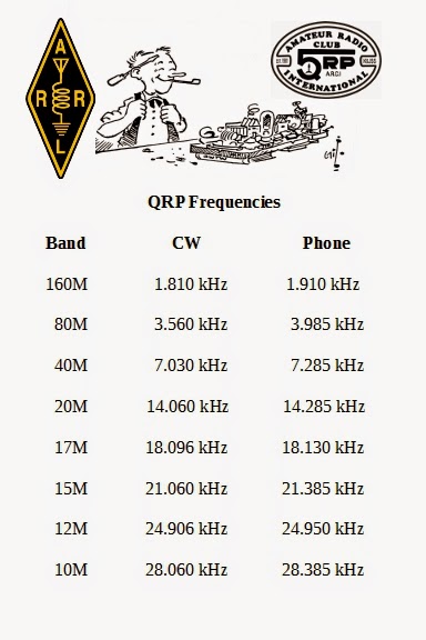
Feel free to save the JPG as an image on your own computer and print it out, if you like. I also have it as a doc file if you'd like to edit to suit your needs. An e-mail request will get it sent to you.
72 de Larry W2LJ
QRP - When you care to send the very least!
Feel free to save the JPG as an image on your own computer and print it out, if you like. I also have it as a doc file if you'd like to edit to suit your needs. An e-mail request will get it sent to you.
72 de Larry W2LJ
QRP - When you care to send the very least!
I was asleep at the wheel
How did I miss this? I've had my September QST for over a week now (we Lifemembers seem to be the last to receive our QSTs!), and I must confess .... today was the first time I've given it a leaf through. I was surprised and gladdened to read a really nice op-ed piece by good friend Jim W1PID on page 101.
Jim shared his thoughts on the changing face of Amateur Radio in celebration of the ARRL's 100th anniversary, but yet focused on the things that remain the same through the changes. The joy, the excitement, the satisfaction, the fun.
Good article, Jim and I'm glad the Newington Bunch had the good sense to publish it!
72 de Larry W2LJ
QRP - When you care to send the very least!
Repairing a Kenwood TR9500, Part1 – The Diagnosis
A fellow SKARS club member picked up a nice condition Kenwood/Trio TR9500 70cm all-mode transceiver (circa 1980) from the Hamfest last year for not a lot of money and he hoped to use it for the UKAC contests unfortunately it proved to be faulty.
From the description of the fault and studying a downloaded service manual I suspected a relatively simple fault and saw an opportunity to acquire it and offered to buy it for the price he had paid. However I have decided to be more charitable rather than mercenary and have offered to give it a look over and repair it for him if I can.
The fault as described was the rig receives okay but on transmit there was a carrier on FM with no audio and a very quiet SSB signal. A faulty microphone had been ruled out and someone had suggested a bad connection internally. Due to the compactness of the unit and the difficulty in dismantling no one had felt confident to attempt any further inspection. I wasn't so sure this was the issue so at the last meeting I picked up the rig and currently have it on the workbench.
I want to confirm the fault first and so I connected up a dummy load and RF power meter and using the FUNCube Dongle SDR I could observe and monitor the output signal. Sure enough on FM there was a nice carrier at 10W with very faint audio, on SSB there was a small visible signal again with very little modulation. Whistling, blowing and tapping of the microphone could be seen on the waterfall... just!
I connected a switch to the Morse key input and confirmed the rig transmitted in CW with no issue.

On the block diagram there is a switchable tone burst oscillator for repeater access and the output of this is joined to the output from the microphone amp. Encouragingly the tone burst can be clearly seen and heard in the transmission again pointing to an issue with the microphone amp.
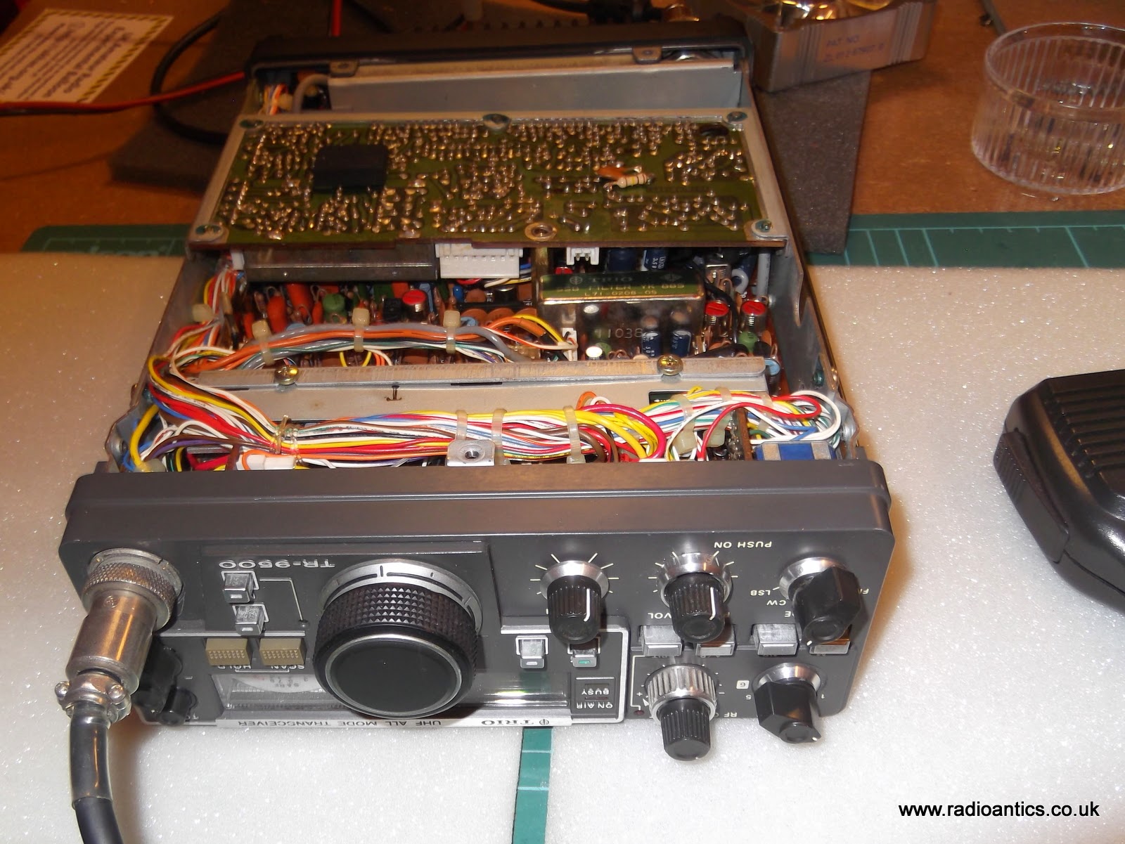
To get to the carrier unit PCB it was a simple matter of removing the bottom cover. The PCB is held in a metal frame mounted with five screws and can be lifted out, as pictured above. But before I did that I checked the continuity to the microphone socket and the 8V supply to the amplifier circuit and both were fine (see diagram below)
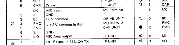

The poor quality image from the scanned service manual shows the bottom of the carrier unit, this is the side of the PCB visible without needing to remove it. The microphone connector is in the top left, putting an oscilloscope on the microphone input (pin1) a signal was observed, however the output (pin8) had an almost identical signal with little or no amplification. Injecting a low level audio signal from the a generator on this pin could be seen and heard in the transmitted signal. This observation together with the tone burst seemed to confirm the other audio circuitry was functioning normally and the microphone amp wasn't.
Actually removing the carrier unit PCB proved a bit tricky as it has a number of small and very secure connectors with ageing and delicate wiring, but I did manage to extricate it and a visual inspection didn't show up any obvious issues such as broken tracks or joints.

This is the detail of the microphone amplifier section from the schematic. Using a meter I have checked the continuity of tracks and have checked all the resistors for shorts or open circuits and they all read the correct values. The capacitors all look okay and checking the signals either side of C3 the C7 coupling capacitors show they are functioning correctly. This left Q1 a 2SC2240(GR) transistor as the likely culprit and I have ordered a replacement which should arrive in the next few days. I am hoping this will make it spring back to life.
From the description of the fault and studying a downloaded service manual I suspected a relatively simple fault and saw an opportunity to acquire it and offered to buy it for the price he had paid. However I have decided to be more charitable rather than mercenary and have offered to give it a look over and repair it for him if I can.
The fault as described was the rig receives okay but on transmit there was a carrier on FM with no audio and a very quiet SSB signal. A faulty microphone had been ruled out and someone had suggested a bad connection internally. Due to the compactness of the unit and the difficulty in dismantling no one had felt confident to attempt any further inspection. I wasn't so sure this was the issue so at the last meeting I picked up the rig and currently have it on the workbench.
TRANSMITTER CIRCUITLooking at the block diagram of the carrier unit and the above functional description in the service manual I suspected the microphone amplifier Q1 to be faulty.
The microphone signal is amplified with the microphone amplifier Q1 (2SC2240(GR)), which is commonly used for both SSB and FM transmission modes and is incorporated in the carrier unit (X50-1720-XX). The amplified signal is then fed to both the SSB and FM circuits.
I want to confirm the fault first and so I connected up a dummy load and RF power meter and using the FUNCube Dongle SDR I could observe and monitor the output signal. Sure enough on FM there was a nice carrier at 10W with very faint audio, on SSB there was a small visible signal again with very little modulation. Whistling, blowing and tapping of the microphone could be seen on the waterfall... just!
I connected a switch to the Morse key input and confirmed the rig transmitted in CW with no issue.
On the block diagram there is a switchable tone burst oscillator for repeater access and the output of this is joined to the output from the microphone amp. Encouragingly the tone burst can be clearly seen and heard in the transmission again pointing to an issue with the microphone amp.
To get to the carrier unit PCB it was a simple matter of removing the bottom cover. The PCB is held in a metal frame mounted with five screws and can be lifted out, as pictured above. But before I did that I checked the continuity to the microphone socket and the 8V supply to the amplifier circuit and both were fine (see diagram below)
The poor quality image from the scanned service manual shows the bottom of the carrier unit, this is the side of the PCB visible without needing to remove it. The microphone connector is in the top left, putting an oscilloscope on the microphone input (pin1) a signal was observed, however the output (pin8) had an almost identical signal with little or no amplification. Injecting a low level audio signal from the a generator on this pin could be seen and heard in the transmitted signal. This observation together with the tone burst seemed to confirm the other audio circuitry was functioning normally and the microphone amp wasn't.
Actually removing the carrier unit PCB proved a bit tricky as it has a number of small and very secure connectors with ageing and delicate wiring, but I did manage to extricate it and a visual inspection didn't show up any obvious issues such as broken tracks or joints.
This is the detail of the microphone amplifier section from the schematic. Using a meter I have checked the continuity of tracks and have checked all the resistors for shorts or open circuits and they all read the correct values. The capacitors all look okay and checking the signals either side of C3 the C7 coupling capacitors show they are functioning correctly. This left Q1 a 2SC2240(GR) transistor as the likely culprit and I have ordered a replacement which should arrive in the next few days. I am hoping this will make it spring back to life.


