Posts Tagged ‘’29 style’
 The Importance of 1929 – Part 2
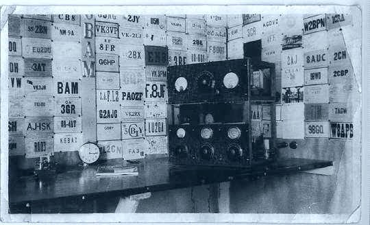 |
| W6BAM - 1929 Compliant. Courtesy : N7RK |
It wasn't long before the ARRL shifted its focus to the new days ahead and seemingly, every issue of QST leading up to the 1929 implementation date, addressed the topic. It is of interest to see how the ARRL interpreted the new rules and developed a strategy to meet the requirements. Many of the rules were broad enough to allow for varied interpretations, all of which could be compliant. In hindsight it seems they made a very good choice on the best way to tackle the present mess on the ham bands...to inform every ham possible of his or her responsibilities for meeting the coming challenge and to show them how.
As far as amateur 'experimental' radio was concerned, the delegates addressed several critical points...in fact, the very recognition of amateur radio itself was a significant step forward for hams worldwide:
"Article 1, {16} the term "private experimental station" means -- (2) a station used by an "amateur," that is, by a duly authorised person interested in radio technique solely with a personal aim and without pecuniary interest."
Although not as big an issue in North America, where governments had long-supported ham radio, for many countries it would mean operational status would now be recognized. The ARRL's campaign to convince hams that their stations must be 'DX-ready' was now given some teeth. Thus began the campaign to convince hams that their 1928 junk must go:
"...for the great average of American amateur stations...it is not a reassuring spectacle in view of next year's requirements. We seriously doubt if as many as one-half of one percent of the active stations to-day are good enough to offer their operators any reasonable chance of success in international work next year. The rest, we think, will have to be rebuilt....floppy waves, bum notes, crawling frequencies, too-big condensers, sloppy practices, haywire assembly, and lack of precision measurements...These must go.. " [QST Editorial, May, 1928]
It sounds alarmingly descriptive of our annual BK Party...but proclaiming that 99.5% of U.S. amateurs would need to rebuild was surely a bold statement and one, as time went on, was gradually toned-down in QST editorials.
Addressing the 'haywire assembly' issue, articles soon appeared showing better construction practices for earlier familiar designs, the self-excited favorites.
 |
| Courtesy: WØVLZ |
Read with caution as you will likely be tempted to begin the parts-search for you own version soon after. It was Niel's superb series of videos that inspired my interest in 1929 construction.
 |
| Hull's 1929 MOPA. Courtesy: http://www.arrl.org/ |
 |
| Hull's High-Powered 1929 Self-Excited Transmitter. Courtesy: http://www.arrl.org/ |
The second article in the issue, "Adapting Medium and High-Powered Self-Excited Transmitters for 1929 Service / Some Design, Constructional and Tuning Considerations Involved", was described by Hull...
"For a week or more, the Laboratory was filled with odors of burning bakelite, hard rubber and wood, and at times whiffs of smoke drifted lazily across the tables -- but in the end our pulse had returned to normal, for we had found that even 250-watt self-excited transmitters can be made to behave in a 1929 manner with just the same treatment we had given the low-powered set".
As noted earlier, it was of interest to see how the men at ARRL interpreted the new rules to such an extent as to call for a complete overhaul of transmitter construction. The Washington delegation had only provided a broad hint as to what must be done regarding stability and spectral purity, while still craftily ensuring that transmitters would always be required to remain "state of the art":
"Article 5, {18} (3) ..the frequency of the waves emitted must be as constant and as free from harmonics as the state of technical development permits"
The ARRL took this opportunity to push the "state of technical development" as it concerned amateur radio. Hull defined the requirements for a 1929 signal as:
"...must be entirely within the limits of the band....its frequency 'flutter' due to irregularities of plate supply must not exceed about 1/30 of 1% (approximately 250 cycles at 40 meters). In addition, the frequency of the signal must be relatively constant. The signal must not 'shimmy' as the antenna vibrates, it should not 'chirp' as it is keyed, nor can it "creep" appreciably as...the tube heats. In short, the frequency of the first dot transmitted should be within 1/10 of 1% (about 750 cycles at 40 meters) of the hundredth dot, even if the plate has reddened...or the voltage drifted. At the end of a few hours of operation the frequency should not have strayed much further." [QST August, 1928]
By today's standards, not a tall order, but in 1928, there was much to be done.
With the deadline fast-approaching, the vigorous campaign to drag hams out of the cesspool of clicks, harmonics, wide signals, raw AC and into the promised land had begun....lead mainly by the hands of George Grammer, Ross Hull, James Lamb, Robert Kruse and Beverly Dudley, nirvana was just over the horizon and surely could be reached .....but only if they rebuilt their 1928 'heaps'. (cont'd)
The Importance of 1929 – Part 1
When it comes to the Bruce Kelley QSO Party and the rules involving the use of circuitry and tubes popular in 1929 or earlier, some have enquired..."Why 1929...what was special about that year in particular?"
Over the past few nights I've spent some enjoyable hours reading QSTs from the late '20's. It seems that 1929 was really the beginning of much that we have come to recognize, for all of our lives, as 'Amateur Radio'....but to answer the question, we really need to go back a few more years.
Prior to that time, and especially in the very early years, amateur radio seemed to have much in common with the 'wild-west'. Rules, if any, were difficult to enforce, as was licensing. May hams operated without a licence, choosing their own call letters. There was a lot of crazy stuff happening...bootleggers, broadcasting music and a general 'every man for himself' approach.
 |
| Headquarters - Courtesy: http://qsl-history.webs.com/ |
With the appearance of QST, in 1915, membership grew quickly and it soon became a sign of notability to be a League member. By the late 20's radio was thriving and growing at unprecedented rates. The U.S. amateur population grew from 16,000 in 1926, to 30,000 in 1932 alone. By 1938 there were 50,000 licenced hams in the U.S.
However, a federal judgement, in 1926, ruled the Radio Act of 1912, to be largely unenforceable, creating even more chaos amongst broadcasters. Things were getting somewhat chaotic in the amateur radio world as well as in the commercial field. The time was ripe for some serious changes.
In order to gain some control over this new technology and the chaos surrounding its usage, more so in the commercial field (ships, aircraft, broadcasting, telegraph), the U.S. Congress passed the Radio Act of 1927 thus giving more tools to the recently-established Federal Radio Commission, the forerunner of today's FCC.
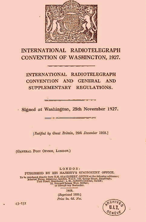
Although the Radio Act of 1927 gave the FRC the power to enforce regulations, it came down to the international agreements hammered out in the winter of 1937 to make things happen. The International Radiotelegraph Conference, attended by representatives from 72 countries, met in Washington, DC to grind out some international 'rules' since the growing popularity and surprising success of the 'shortwaves' was now of worldwide concern.
Much as we see today, the fight for radio spectrum had begun. The 172-page Washington document makes fascinating reading and in it we see the basis for many of amateur radio's beloved fundamentals.
 |
| Courtesy: http://www.arrl.org/ |
The amateur's of 1927 didn't know it yet, but they would soon be deep in rebuilding their stations to meet the 'new requirements' of 1929!
BK Bustle
You may hear plenty of activity in the nights leading up to the Party as various stations burn the cobwebs out of their handmade creations around 3550-3570 in the next few nights...you might give them a call if you hear them as most will be delighted to know that they're getting out of their backyard.
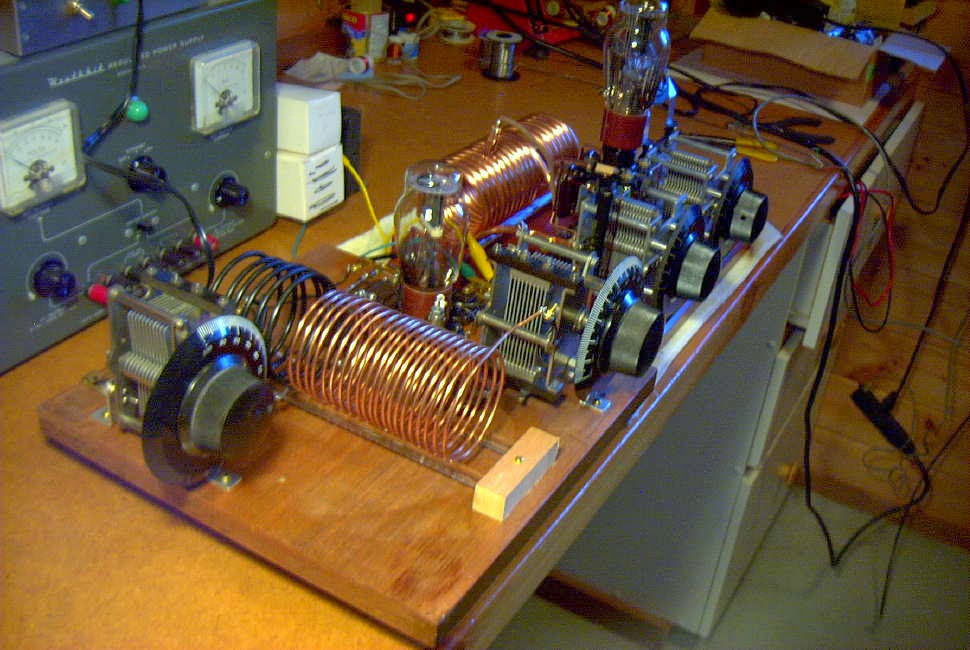
A few weeks ago, in the same spirit of preparation, I began work on a small amplifier for my Hull Hartley transmitter. Ever since entering the BK Party, I have been held hostage by the monster winds which always seem to show up here during early December. Self-excited oscillators connected to blowing antennas create an unusual-sounding signal...somewhat musical....up to about 30km, but after that, somewhat dreadful, as shifts in frequency between keying elements can be measured in tens of Hertz or more and make it difficult to copy a weak signal.
I put the amp together in the original 'ugly construction' style of the 20's, which I'll call 'ugly breadboard'. For the most part, period-appropriate components were used, as it was to be a 'proof-of-concept' project....to see if and how it would work and what changes might need to be implemented in a 'finished' version.
 t t |
| Amplifier stage followed by Hull Hartley exciter on far end. |
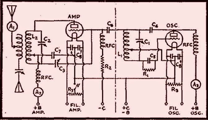
The original circuit, shown below, was published in the February 1931 QST and penned by George Grammer (W1DF), the ARRL's Assistant Technical Editor. Since I already had the oscillator section, I built the amplifier only, making a few modifications.
 |
| Courtesy: http://www.arrl.org/ |
My changes involved removing the B+ from the exposed plate tank coil by putting C7 between the plate and the tank circuit, grounding the coil tap point and shunt-feeding the B+ directly to the plate. As well, the operating bias was changed from the original combination of grid-leak and external fixed-bias (always a pain) to grid-leak bias only. Since I planned to let the oscillator run and key only the amplifier stage, no external (extra) bias was needed. The original system of feeding drive via capacitive coupling from the oscillator tank circuit was maintained as was the 'plate neutralizing' system. With the plate tank no longer carrying B+, a wide-spaced variable capacitor was no longer required for C3. These changes are illustrated below:
 |
| Courtesy: http://www.arrl.org/ |
Testing went smoothly and with the help of a tuned RF-sniffing wavemeter (the actual one I built when I was a brand new15 years old ham!), the amplifier neutralized beautifully. It was unconditionally stable, in spite of the numerous clip leads surrounding the board connecting to the separate Hartley oscillator in a somewhat haywire fashion....it really was a mess. As one other '29 builder (KK7UV) so perfectly described his latest workbench project, it "looked like the transmitter was on life-support!"
Surprisingly little drive was required from the Hartley and it was run at just 200VDC. The amplifier efficiency was around 50% which could probably be improved upon with careful attention to biasing values, shorter leads and more efficient antenna coupling. On 80m, the only band that I wound a coil for, keying was clean and very nice (an advantage of being able to run the oscillator at low level). Without too much effort, 15 watts out was easily obtained...far too much for the BK Party.
Tapping down on the tank coil for 40m operation proved to be a different story as the note sounded like a buzz saw...very raspy and nasty. To really undertake a fair test, a dedicated 40m tank coil would have to be used as well as a much 'cleaner build'.
The rat's nest of unwanted coupling of both RF and AC ripple was showing through on this higher frequency.
For multiband operating events, such as the BK, things have to be efficient enough to make band changing and tune-up procedures quick and simple and in its present haywire form, the amplifier would just not be 'contest-friendly'.
All in all it was a very valuable building exercise as a LOT was learned. I am now convinced that for a true MOPA (Master Oscillator Power Amplifier) combination to do what is needed will require an all-in-one style of construction....both oscillator and amplifier on the same board, with short leads and little chance for unwanted parasitic-coupling between stages. With separate coils for all bands and calibrated dials, tuning and changing bands would be very much easier than trying to couple two separate units together. I can see why the struggle to get the original '29ers away from their simple Hartley's and TNT's and over to MOPAS went on for several years.

So once again I am at the mercy of the wind-gods and hoping for two back-to-back Saturdays of quiet BK-friendly air...in early December...on the west coast...by the ocean...yeh, right!
More BK Building
My recent 'Building For The BK' blogs have tempted at least one ardent homebrewer, John (VE7BDQ), to dig into his junkbox stash to create a nicely-working BK rig....it's a Colpitts oscillator using a pair of 45's in push-pull. His lash-up is now working and ready to go on both 80 and 40m and he is contemplating 160m operation with it as well....very nice!

Although John did not have every period-appropriate component available to him, it didn't discourage him from building his BK rig. For too many, this is often a stumbling block that leads to nothing being built....as the boy's of '29 no doubt would have done, he put something together completely from his junkbox.
It will be super to have another left-coast station in this years '29 Party...and a Canadian station to boot!
Anyone else building for the BK? ....there's still a few weeks left.
 |
| 1935 ARRL Handbook. Source: http://www.arrl.org/ |
John and I had a nice QSO today on 80m CW and the rig sounds just great. He reports 240 volts on the plates and a current of 58ma. His scope-measured output is just over 8 watts for an impressive efficiency of just over 60%. It appears that the Colpitts-style is much more efficient than the more popular TNT or Hartley oscillators...well at least more efficient than the ones I built!
Although John did not have every period-appropriate component available to him, it didn't discourage him from building his BK rig. For too many, this is often a stumbling block that leads to nothing being built....as the boy's of '29 no doubt would have done, he put something together completely from his junkbox.
It will be super to have another left-coast station in this years '29 Party...and a Canadian station to boot!
Anyone else building for the BK? ....there's still a few weeks left.
BK Building…
 |
| March 1926 QST. Courtesy: ARRL |
Every year as contest time approaches, I anxiously follow our local weather patterns in hope that the winds remain quiet for the event. For the past few years, the wind has been non-existent...right until zero-hour, when, almost as if a switch were thrown, the wind ramps up to gale-like conditions. Now if you've never heard a self-excited oscillator directly connected to a wind-blown antenna, then be sure to take a listen to this year's BK. These '29 rigs are often not very pretty-sounding, even into a dummy load, but couple them to the wind and things get very 'nostalgic-sounding' quickly. Frequency shifts in the order of several hundred Hertz between letters are not uncommon, making copying a weak signal difficult and almost impossible if listening with a narrow filter. The amplifier will effectively isolate the effects of a shifting antenna impedance from the oscillator stage, making life very much less stressful, come BK time.
My plan is to follow the wisdom of the '29ers themselves, carefully explained in "More Power With Better Frequency Stability" by George Grammer and published in the February 1931 edition of QST. I'm always impressed at how quickly those folks back in the 20's figured out so many of the important "basics of radio" that have withstood the test of time. It must have been an exciting time to be a ham! A glance through any of the numerous radio magazines from the late 20's and early 30's reveals a vibrant market for the homebrewer, with every type of component available. Whether the average ham could afford to buy them in the hungry-thirties is another question.
I've chosen to use another type '10' power triode as my amplifier, as shown below.
 |
| Courtesy: ARRL |
I see the main challenges being coupling conveniently from the oscillator as well as neutralizing the triode amplifier...I wonder, will neutralizing it on 40m (for example) also make it stable on 80m?
As well, since the type '10' uses a directly-heated cathode, if I wish to let the oscillator run while I key the amplifier, a separate filament supply will be required for each tube. With this in mind, I've got the ball rolling this week with the construction of a dedicated '29 rig filament supply. The supply uses two center-tapped 5V transformers with their secondaries in series and brought out to the back panel. This will allow me to use tubes with 2.5V, 5V, 7.5V and 10V filaments...up to 3A.
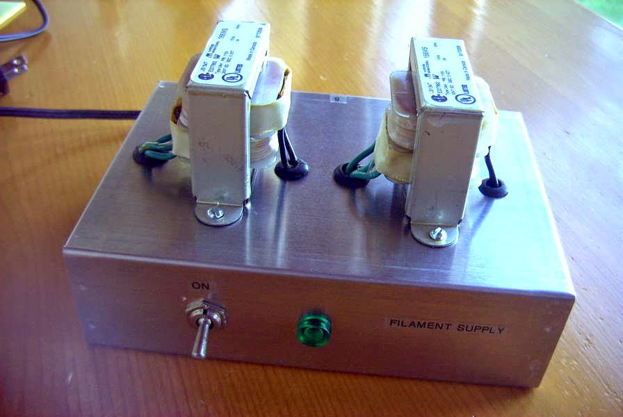 |
| New filament supply |
Are you building or planning anything for this year's BK Party?
’29 Style Transmitters…What To Build? – Part 2

When it comes to putting a transmitter together for the BK, there are a lot of choices! My advice for a first-build '29 rig would be either a simple TNT or a Hartley-style oscillator. Both are easy to get operating and, when correctly optimized, are capable of putting out a nice-sounding signal.
For a first-time build, with the main objective being to have something ready in time for the December BK, I would not be concerned about overall appearance or period-appropriate parts. For now, the only thing that must be period-appropriate is the tube...improvements can come later.
As well, I would not be overly-concerned about running the maximum power of 10W input. If you are able to get a type '10' or the equivalent VT-25, or a pair of 45's, then the legal-limit is easily within reach. Utilizing something smaller, at just a few watts output, should not be considered a deterrent, as BK-operators all seem to have very good ears. Just 2 or 3 watts will guarantee plenty of contacts no matter where you are located!

Shown above is a fine little TNT built by Kevin, WB2QMY, in New York. It uses a very affordable UX-201A triode, originally manufactured in 1925 for radio receivers. Although Kevin's TNT puts out barely 2 watts on 80m CW, we had no trouble working each other in a recent BK QSO Party. If you build it, they will come!
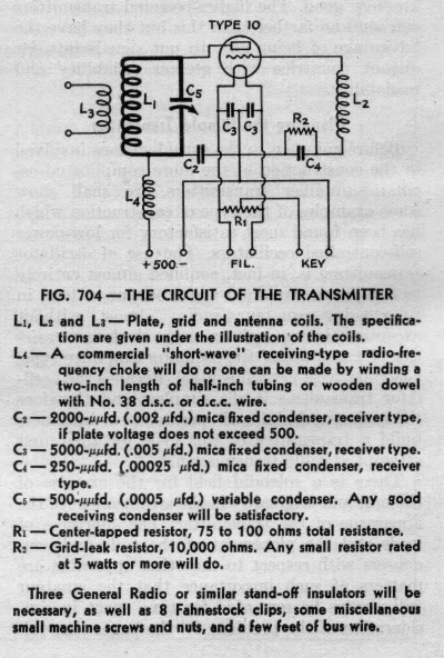
If you prefer to tackle a TNT, here is the information you will need. This circuit appeared for several years in the ARRL Handbook's transmitter-section. I suspect that it was probably built by thousands of young hams in the late 20's and early 30's and affordably introduced most of them to the magic of radio. For more building details, including how to keep high-voltage off of the main tank coil, see the information on my website describing the TNT project.
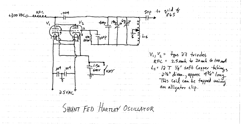
Should you be interested in tackling a Hartley, here is an interesting circuit described by Nick, WA5BDU.
 |
| Courtesy: WA5BDU |
Such a transmitter would readily lend itself to a parallel arrangement of two or more triodes, such as the 27 or the 45 and would develop good power levels inexpensively.
ABØCW has designed a Hartley oscillator using a pair of 27's in parallel and uses them to drive a small amplifier. As described on his website, the oscillator would make a fine stand-alone transmitter with a simple link-coupling antenna circuit.
 |
| Courtesy: ABØCW |
You can find a list of '29-style related building links, as well as a gallery of transmitters constructed by others, at the bottom of my TNT web page here.
And....circuit ideas, help with parts and lots of BK-chat can always be found at the Yahoo AWAGroup where the focus is mainly on building and operating.
’29 Style Transmitters…What To Build? – Part 1
 Most hams in the late 20's and early 30's seemed to be using simple transmitters...one or two tubes at the most. No doubt the poor economics of the time made it difficult to build anything really elaborate but it didn't seem to stop them from getting on the air with whatever they could put together.
New rules for amateur radio signal stability came into effect in 1929, making that a pivotal year for amateurs, resulting in several new ideas for 'modern' transmitters hitting the publications of the day.
All of the simpler, one-tube transmitters, were self-excited oscillators capable of pretty good sounding signals when operated correctly and when the wind wasn't blowing the antenna around. Being directly-coupled to the antenna meant that any variations in antenna impedance caused by antenna wire movements, would result in the note rising or falling in frequency by several hertz with the resultant 'musical-sounding' note. You can usually hear lots of these during the windy winter BK Party!
From what I can determine, the most popular first-time transmitter was the one-tube TNT (Tuned-Not-Tuned) style as it could usually be built with parts stripped from an old broadcast receiver.

With a low parts-count, it was easy on the pocketbook. The grid coil was broadly resonant near the plate circuits frequency, resulting in enough feedback to sustain oscillation. The grid coil really needs to be optimised (a simple procedure) for peak efficiency and note quality. You can listen to the note quality on my own TNT while transmitting on 40m.
The Hartley oscillator is just as easy on the pocketbook as the TNT, and in the opinion of most, capable of an even better-sounding note once properly optimized.
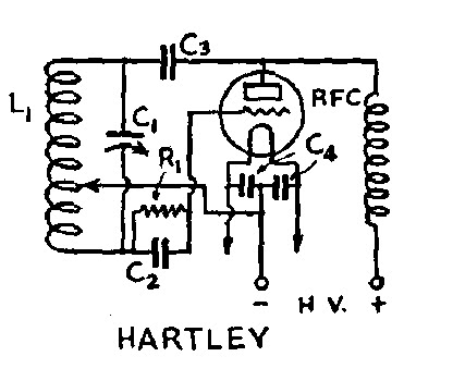
This transmitter is optimized for best note-quality and plate efficiency by finding the correct tap point on L1. Hear my own Hartley's tone while transmitting on 160m.
The third common transmitter of the early 30's was the TPTG (Tuned-Plate-Tuned-Grid).

The TPTG style is a step-up from the TNT and similar in design. Although the added expense of a second variable capacitor made it less popular than the previous two styles, optimizing performance was somewhat easier since the grid circuit could be more readily adjusted for the oscillator's 'sweet-spot' without having to add or remove turns on the grid coil.
All of the triodes mentioned in my previous blog will work well in the above circuits. Keying is normally accomplished as shown below, by connecting the balanced filament resistor on the directly-heated cathode to ground.

It is important to know that construction need not be fancy to get on-the-air for the BK and there is no reason why modern components cannot be used, along with the era-appropriate tube. If you're still undecided, I'll give you some building details to consider next.


