Archive for the ‘radio’ Category
 Super-sizing the “cheap Yagi” (Part 2)
The two most expensive parts of a VHF/UHF Yagi are the boom hardware and the feedpoint. So, I set about eliminating these costs, keeping in mind that I may only have the antenna installed for a year or two at this QTH.
The feedpoint mechanical construction has been addressed in a previous note. However, I should back up and discuss changes from the K1FO Yagi. In its original configuration, the K1FO antenna is fed with a T-match. This is mechanically complex, although some might argue that it’s sturdier than my solution. I elected to feed the antenna with the WA5VJB hairpin design (38-inch element with harpin 1/4-wave stub spaced 1 inch for 19 inches—this is just a convenient and inexpensive ruse for direct feed without splitting the driven element) for the moment. Yes, I am aware that the K1FO antenna has a natural input impedance considerably lower than 50 ohms, but this is just the first (essentially mechanical) prototype. I’ll do some modeling eventually and determine if I can or should optimize it further.
There are four choices for a boom: PVC pipe, fiberglass, aluminum, or wood. PVC is heavy and too flexible for anything longer than two or three feet. (I see people asking questions in forums all the time about building antennas out of PVC. Why bother when wood and aluminum are so readily-available?) Fiberglass is light and strong, but unless you have access to a lot of it, it’s the most expensive of these options and the most difficult to work. That leaves aluminum and wood. Aluminum is hard to beat for strength-to-weight ratio and ease of working. But, wood will give it a run for its money on cost for a reasonable strength up to a point. Since I had a bunch of wood readily available, I elected to build the boom from wood. This is probably pushing the practical upper limit for a wood-boom antenna.
For the boom, I used three pieces of 1 x 2 select pine that was weatherproofed with a clear lacquer:
![]()
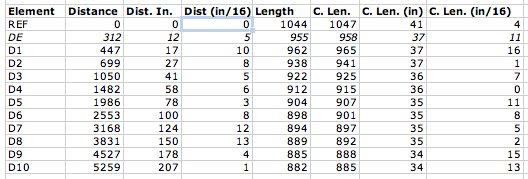
The 0″ reference point for the element position measurements is at the left end. Don’t forget to leave a couple of inches at the end.
The original WA5VJB designs were optimized for 1/8-inch diameter elements, which is fortunately quite inexpensive (part #8974K14, $2.11/each, working out to a $12.66 antenna, plus about $5 for shipping…you can buy a lot of Al rod and still ship it for $5.) from McMaster. The K1FO designs are provided for 3/16- and 1/4-inch elements, costing $4.13 or $6.03 for six-foot pieces respectively. That was a little rich for my budget, but then I looked at the Metric-dimensioned 6061 aluminum rods. 5 mm is a little more than 3/16 inches and these rods are only $1.64/each ($19.68 for 12 six-foot lengths; examining the element length table below should give you an idea how much savings there is if you get some buddies together to build a few of these…forget buddies, build an EME array)! So, I built the antenna out of 5-mm diameter rods using the 3/16-inch dimensions.
The table contains initial element lengths and offsets in inches. Do not build this antenna! (Do as I say, not as I do.) It appears to be a good performer, but it has not yet been optimized as discussed above. The columns “Dist (in)” and “Dist (in/16)” refer to the integer and fractional portions of the distance, respectively. Likewise, “C. Len. (in)” and “C. Len (in/16)” refer to the element lengths.

Using a cheap Dawia SWR meter at the end of the feed cable, I can tell that the SWR is less than 1.7 across the low portion of the band. Actually, it’s relatively flat around 1.5-1.7 all the way up to 144.5 MHz where I quit measuring. The pattern is apparently good. My “local” beacons that I can pretty much always count on are WA1ZMS (to the southwest) and W3APL (to the northeast). WA1ZMS runs a lot of gas to an excellent antenna system from an even more excellent QTH. I can fade either of them into the nulls when listening to the other. When I turn the antenna, they fade pretty rapidly into the noise, as well. Good F/B, F/S, narrow forward lobe, etc.
So, the upshot is: I built the unmodified K1FO-12 design for 144 MHz on a wood boom for $30 and about 5 hours of tinkering with basic hand tools. I can turn it and my 3-element 50-MHz Yagi with a 60-year-old CDE TR-2 TV rotor. My TS-700S happily blasted 10 watts into it even at SWR of 1.7. I’ll need to verify the cable loss and determine if my newly-acquired Mirage B3016 will tolerate it.
I will post models and photos eventually (once I find the files again…oops) for the 11-element disaster and the 12-element one I built. Yagis are tricky to optimize well. So, I’m somewhat disinclined to mess with the K1FO design and more likely to switch from the WA5VJB driven element to the T-match if I decide that the SWR matters that much.
Super-sizing the “cheap Yagi” (Part 1)
One of the frustrations of doing VHF on the cheap is getting enough gain to make your low-power signal loud (or simply being heard) at the other end. I had a couple of options with my 6-element WA5VJB “cheap Yagi” on 2 meters:
- Increase the height of the antenna. This is impractical at the present QTH without installing a tower. Actually, the tower would have been possible but I wasn’t ready shoot first and ask questions later with it. Nor was I ready to have my folks spring some Rohn 25G out of storage in their garage for the trip here when I had the opportunity (a truck bringing some furniture from them).
- Run lower-loss cable. I have regular old RG-8 (PE dielectric) running up to the antenna. It’s only about a 50-ft run. So, I’d be hard-pressed to do a lot better. I did figure out how to recycle improperly-installed N-connectors for LMR-600 from a dumpster-diving excursion. Although I have twenty-some connectors, I haven’t yet secured any scraps of LMR-600 to use. This is a future consideration. At $1.50/ft, LMR-600 would still cost $75. No deal.
- Stack multiple 6-element antennas. This is actually a good idea that I’m keeping in the back of my head for the future. It would be nice to do something like this. Maybe some day.
- Launch a rocket to do a chemical release whenever/wherever I needed a sporadic-E layer. Unfortunately, you can’t launch rockets over land. (Update: I was reminded later that this is not 100% correct.) Furthermore, at a megabuck per shot, it’s not cost-effective.
- Dispense with the 6-element design and go for something bigger.
I elected option #5.
The first step was to consider suitable designs. I tried scaling the 11-element 432-MHz cheap Yagi to 144-MHz. Fail. A NEC model showed that the pattern stunk and the input impedance was pretty far from 50 ohms. Knowing that W5UN had built an array of wood-boom antennas for his EME setup, I looked into readily-designed options.
The ARRL Handbook (1993 edition for reference) and ARRL Antenna book (18th edition) have the K1FO optimized Yagi designs in them. This antenna has been around for a number of years (clearly) and is available commercially from Directive Systems. It seemed like a relatively good choice. So, I moved forward with it…
Feeding the WA5VJB cheap Yagis
The WA5VJB cheap Yagis are a great way to get on VHF/UHF without spending a fortune on commercial antennas. While it is practical on the UHF/microwave bands to use a copper driven element, it is less practical on the 144 and 222 MHz bands. I know that McMaster carries copper and brass rods, too. But, I also like to have a coax connector at the feedpoint. Since I am in the process of building what amounts to a “super cheap Yagi” (note that’s not a “super-cheap Yagi,” the hyphen matters; will report on this in the future), I figured I would share my feedpoint for aluminum driven elements.
While wandering through the electrical aisle of the local big box hardware retailer about six months ago, I discovered the Thomas and Betts ADR6-B2 (try the ADR6 for a drawing of a similar part) grounding lug. This looked like a good candidate for the cheap Yagi feedpoint, especially costing only $1 for a pair. In order to fit an SO-239 flange-mount connector to the ADR6-B2, I cut off the portion of the lug with the bolt hole and drilled my own hole (#43) and tapped it 4-40. I did the same to the other piece. I did not cut off the lug on the second one, but I should. Then, I soldered a short piece of wire to the center conductor of the SO-239 jack and added a lug to it. Here are the parts so far:

Then, I assembled the whole mess on the J-shaped driven element (dummy used for photos) using two 3/8″ 4-40 screws and a lock washer. Note that the ADR6 lugs are installed on opposite sides of the element.

And, after installing on the wooden boom, it looks like this:

It’s not quite square and some mechanical strengthening is in order before it goes up in the air. But, this is a considerable improvement over what I’m using now. Ty-wraping the coax to the boom will provide considerable relief to the connector and it’s attachment. More details will be forthcoming on the antenna, if it works. Stay tuned!
Travel with Radios and Antennas
Every now and then, there is a question on one of the e-mail lists or forums about traveling by air with radios and antennas. In my experience, most travel headaches can be minimized by adhering to a couple of simple rules:
- Make it easy for the security (and Customs, if international) inspectors. Pack everything neatly so it’s easy to search, even if you’re not present (checked baggage). Label everything. Include documentation and instructions on how to quickly disassemble things if needed. Be courteous if searched. This is not the time to “educate” inspectors about amateur radio.
- Carry your radio and computer as hand luggage. I think everyone knows this by now.
- Put antennas into a sensible container and check them. I’ve heard of golf club carriers, ski bags, fishing rod carriers, and cardboard boxes. I use a 4-inch thin-wall PVC drain pipe that’s about 48 inches long. It has a black rubber cap on one and a drain plug on the other. This may have problems in the automatic baggage-handling systems of some airports like O’Hare. The sporting equipment bags are better because the airlines know how to handle them. It makes sense to use a carrier that might be similar to other baggage going to your destination. But, in reality if you just call it your “ski bag” or “golf bag” at the counter, the agent will never ask what’s in it (aside from the usual security questions). Also ensure that this bag is acceptable on all your flights, including island hoppers.
- Keep as low a profile as possible, but don’t be weird or break the law. Practice moving fluidly with all of your gear. Expect to be questioned and prepare for it.
If the trip is international, every country is different. So, it’s helpful to have either a resourceful, intelligent local fixer or at least to discuss your plans with someone who has been there before. However, most countries that receive a lot of tourists and have relatively easy reciprocal licensing requirements will not pose any problems.
CW DX pranks
One of the perpetual frustrations of being in a rare (in ham radio terms) location (or just having a big signal from an exotic location) is handling the ensuing “pile-up” of stations calling you, separating them so you can hear them and keeping them from interfering with your signal. The sought-after (“DX”) operator must maintain control of the pile-up or pandemonium breaks loose. A tried and true technique for controling a pile-up is to spread callers out in frequency above the DX operator’s frequency, which should remain clear, except when the DX is transmitting, of course. This is called “working split” and on CW (Morse code mode), the DX operator indicates this condition by appending “UP” to his calls.
For unknown reasons, this concept is lost on some operators, who call repeatedly on the DX’s frequency much to the consternation of everyone else who is trying to make contact. Sometimes, it’s an honest mistake and after some “helpful” operators send “UP UP UP UP” a few times (also on the DX’s frequency), the offender catches on. But, in just about every pile-up these days, there’s always one or two operators at the shallow end of the pool of clue. Tonight’s JT5DX pile-up on 20 CW (listening from the mobile on the way home from work) was no exception.
I’m never sure whether to laugh or hang my head in shame when this happens…but, now and then one of the other operators in the pile-up will answer the poor clueless soul impersonating the DX and give him a contact! It shuts them right up and is usually good for a laugh. I do feel a little bad every time I hear it…but, if they don’t get it when the pile-up police send “UP UP” and the DX sends “UP”, how can you explain it to them?!
K8GU/M (or how convert your 1999 Ford Escort into a real head-turner)

When we got married, the Escort I was driving had gone to my parents in exchange for a larger vehicle with an automatic transmission and a 6-cylinder engine (all three points nods to Sarah, although I admit that it was a much better ride for the kind of driving we did). With the transfer of the Escort, my HF mobiling days were on hold, although I kept the gear.
In order to finance a DSLR a couple of years ago, I sold-off some ham gear I wasn’t using, notably the HF mobile equipment. I didn’t manage to sell the tri-magnet mount I borrowed from N8ET for the 2004 MnQP and a rather dismal attempt at WiQP. This mount had an interesting life, which included being destroyed at 75 mph on I-94 north of the Wisconsin Dells. I drop-shipped a replacement to N8ET, but had the good fortune of finding similar donut-shaped magnets and some heavy adhesive vinyl at Ax-Man Surplus. So, with a little epoxy and elbow grease, I fixed the mount while I was still in Minnesota. It lived to ride again in several QSO parties before my futile efforts to sell it. I raised the requisite capital for the DSLR before the mount sold. So, I kept it.
When we moved the DC area, it quickly became apparent that we were going to have to relinquish our delightful position as a one-car couple and the Escort returned to our lives, probably to the chagrin of my father and delight of my mother. Dad later passed along a Yaesu FT-5100 and mag-mount VHF/UHF mobile antenna which I promptly installed. But, I really longed for HF CW in the car like the good old days. So, a few weeks ago, I plunked-down $30 for some knock-off Hamstick-type HF antennas for 20 and 40 and put the Yaesu FT-840 back in the car. (Astute observers will note that I have a 100% Kenwood fixed station and a 100% Yaesu mobile station. The IC-290H and the DJ-580T are anomalies that I permit to persist in my life for various reasons.)
There is nothing like listening to JAs via long-path on the way to work…and getting funny looks from the other commuters at the same time. A car full of teenagers waved once. Friends and relatives have called it everything from “a space ship” to “a hunk of junk” (thanks, Rachel).
IC-290H dial frequency offset

Some time back, I had the good fortune to stumble across a broken IC-290H at an attractive price. The IC-290H is a synthesized mid-1980s 25-watt 2-meter all-mode transceiver. Since I had been contemplating a radio to use as the IF to my W1GHZ transverters for 903 through 3456 (yeah, still need to build/integrate all of these), I jumped. The problem was described as an offset of some tens of kHz between the dial frequency and the actual transmit and receive frequencies. Since the IC-290 lacks a user community like the TS-600 and TS-700 (my other 2-meter all-mode radio), I went to Google and then posted a quick inquiry on the Stanford VHF e-mail list to see if this was a common problem. Google produced nothing and the VHF list produced the usual “get the Service Manual” response. Since I already had the Service Manual thanks to the previous owner, I was set.

The synthesizer (“PLL”) in the IC-290H has at its heart a VCXO (shown above). The control voltage biases varactor diodes D2 and D3 in a tank circuit with crystal X1 operated between the series and parallel resonant frequencies (as a very high-Q inductor). Contributions to the control voltage come from the microprocessor (red dot), the receive incremental tuning (RIT, blue dot), and an overall bias of -9 V derived from 5 V using DC-DC converter IC2.
In the “PLL Adjustments” section of the Service Manual, the VCXO adjustments are outlined, checking the synthesizer output with a frequency counter. I noted that as I changed rotated the VFO encoder on the front of the radio and the digits changed on the display, the output frequency of the synthesizer changed accordingly. Similarly, the RIT caused the frequency to shift. Neither of these things were surprising since I could tune in different stations before. In USB mode at 145.998.5 MHz, the synthesizer should output at 134.250.0 MHz. I read it at 134.230.21 MHz, clearly the source of the almost 20-kHz offset. I nudged potentiometer R2 (against the vehement warnings of the Service Manual) and the output didn’t change. For good measure, I swept R2 over its entire extent with no change.
R2, it seems, controls amount of the available -9 V bias applied to the varactors. I checked the -9 volts line. Zero. Who stole the bias from the cookie jar? The 5 V line was sagging down to 4.23 V.
I removed IC2, which is in a metal can that resembles an overgrown Mini-Circuits mixer and has only “DP-1″ stamped on the cover in black ink. For kicks, I drove this little guy with 5 volts into no load and got well over -100 V out. Did this punk destroy other parts in my synthesizer? I put this question to Dad, who happened to be here over the weekend. He suggested that it might require a load to produce a regulated output. Good thinking. Nothing on the synthesizer board appeared to be charred. So, my theory was unlikely and I proceeded.
Without IC2, the 5 V line bounced up to 4.95 V. And, the output side (connected to L6) showed a DC short to ground. If you trace the circuit from the output of IC2 to one of the legs of R2, nothing should show a DC short. I looked for bridged solder traces. None. Taking the divide an conquer approach, I removed R10 (green dot), to isolate the entire RF portion of the circuit. Still shorted. So, this left the following three suspects: two 0.1 uF ceramic disk capacitors and a 10 V, 100 uF electrolytic. Since electrolytic capacitors, especially older ones, have a bad reputation for causing problems, I interrogated it first (C20, purple dot). Bingo.
The only 100 uF capactor I had on hand that even came close to fitting was a 50 V unit from a previous repair. I squeezed it in—it’s the big brown one against the edge of the case in the center of the photo below. Note IC2 “DP-1″ in the lower right corner.

So, I plugged the radio into a power supply and antenna. And, low and behold…it was about back on frequency. So, I completed the synthesizer and RIT adjustments in the Service Manual and put it back together. It actually receives WA1ZMS/B on 145.285.0, which, Doppler notwithstanding, is GPS-locked at 145.285.000… Stay tuned for the low-drive transverter IF modification in the next few months once I start building them again.


