Archive for the ‘radio’ Category
 Creating open-source ham radio hardware with Kickstarter
 August 30th, 2015 |
  Author:
 When I started my company last year, it was mainly set up as a design consulting outfit to pick up a few jobs on the side. At the end of 2014, it became much more when I decided to plunge full-time into my own work. At the time, one of my respected friends and colleagues, Don Powrie of DLP Design, said to me that the only way to make consistent money is to have a product line rather than rely on consulting work. I’ve been thinking of how to bring that to market ever since. I could certainly design some familiar products to me, but they would get lost in the plethora of similar items. I needed something unique.

I started out with a 5V @ 5A design. I drew the schematic and completed the PCB layout and started to check pricing and availability of the parts. Most everything was available at Digi-Key, and the Anderson Connectors from Mouser, but the total was getting close to where I wanted the selling price to be. For a $35 computer, I couldn’t justify a $70-$80 power board!! The DC-DC converter also had a very large ground pad for heat dissipation. I wanted this project to be able to be hand-soldered and started wondering about that large pad. That design got scrapped and I started looking for another buck converter. There were several TI and Linear products I considered, but they would have required a reflow oven – either with a center pad, as a BGA, or leadless formats. Then I found the Alpha & Omega AOZ1031AI. This is a 8-pin SOIC without any special pad. The only heat-dissipation suggestion was that pins 7 and 8 do not have any thermal relief, but connect fully to the surrounding plane. I selected larger commodity parts (0805) that could be seen without a microscope and created the layout, and all parts were in stock at either Digi-Key or Mouser Electronics. I got everything on order, and even managed to get a couple free PCBs from Pentalogix. I had attended a Pentalogix-sponsored Cadsoft Eagle webinar at Newark and the perk was a code for two boards. I just had to cover shipping.
I did other tests: Let it run for 8 hours (check), ramp voltage from 6 to 18V input (check). At 7V input, the Pi kept rebooting. At 8V, it was solid – well past the design spec. Same at 18V.
Next up was the load test. With 2A going direct to load resistors, I was still able to run the Pi with all four USB ports occupied. I even dipped the supply to 8V. The bench supply showed about 1.8A output. Based on an approximate 80% efficiency of DC-DC converter, I calculated I was drawing about 3.5A on the 5V side – a little past its limit, so backed off the load. I’ve been running this directly from my radio supply now for several days, and the Pi keeps chugging along.

I’m a believer in open-source hardware and software. This project will be published in the coming days, probably on GitHub. Eagle uses XML design files, so version control should work just fine. I still need to write the manual, but everything will be made available as soon as I get the proper README and LICENSE files in place. All of my work for this project is published under the Creative Commons Attribution and Share-Alike license. The hardware itself is published under the TAPR Open Hardware License.
July Greenland Trip
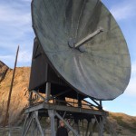
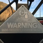
Made a quick trip to Greenland for three days in July to work on some equipment there. I did not get on the air due to work activities and operation of the incoherent scatter radar whose modulator trashes the HF bands if you’re close to it (i.e., same building). A few photos, though. These were all shot with an iPhone 5s, nothing fancy.




50-MHz transverter update (Psst! Newark has cheap 22-MHz crystals)
A few years ago, I built a 50-MHz transverter to operate 6m with my Kenwood TS-930Ses. I subsequently replaced the two 930s with an Elecraft K3/100 and Elecraft K2/100. The K3 has 6m and I sold off my TS-700S (and my 6m Mirage brick amplifier) to help finance the internal 2m board for the K3. The problem with this arrangement is that I can’t be on 6m and 2m at the same time. I recently assembled and added the SSB board and transverter interface to my K2 (no time to blog about this but they were straightforward additions like everything from Elecraft), now making it an attractive IF for the 6m transverter (and the Microwave Modules 432 transverter I have on the shelf and the 222-MHz transverter I plan to build sometime).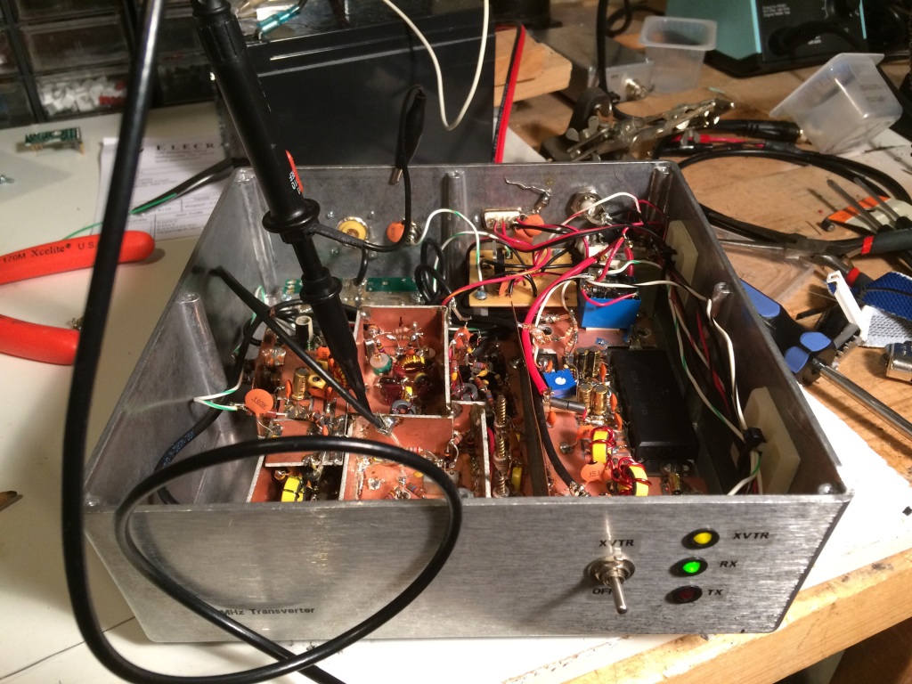
Enter the problem: Because I was thrifty about building the transverter at first, I had used an inexpensive and widely-available 24-MHz crystal for a 26-MHz IF. The TS-930S happily worked here (by the way, pro-tip: A lot of guys say that they liked to have the wideband transmit mods on their HF rigs so they could have a wideband signal source for testing/transverters/etc. The TS-930S will give you a low-level TX out anywhere through the transverter port, even if you don’t have the mod. Well, at least my PIEXX-equipped 930 did). However, the K2 only allows a select set of transverter IF bands to be used natively. Good fortune shone upon my endeavors when I did a quick Google search for 22-MHz crystals and one actually popped up at Newark/Element14 (part number is 86R1720, get ‘em while they’re hot)! Even better news was that it was on closeout for 12 cents apiece! I splurged and bought five, along with some other parts for another project or two I’ll post about eventually.
I carefully peeled back a layer of dead-bug components, extracted the 24-MHz crystal, and replaced it with the new 22-MHz variety, sacrificing only one 4.7-k resistor, an easily-replaced stock item at K8GU. The LO came up about 5.4 kHz low and I couldn’t peak it any higher. So, I’ll either have to futz around with the loading of the crystal or (more likely) load an offset in the K2’s transverter band entry for 6m.
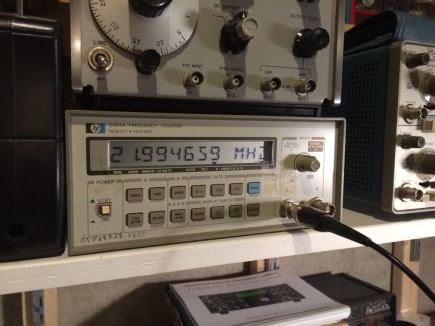
The local W3APL beacon popped up at 28.0694 MHz, which is consistent with the offset I observed above. Now, I just have to get the other interfacing juju worked out to get the K2 to properly command the transverter to transmit and feed it the proper drive level.
Converting the HP ESP120 Power Supply
Quick notes on converting the HP ES120 2950-watt blade server power supply to run “48-volt” amateur radio amplifiers. The power supply I have has a slightly different in configuration from the one described by W8ZN on the K8GP site.
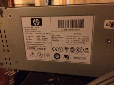
I picked up the power supply on good terms at Dayton some years ago and finally managed to get around to hooking it up after I put two 240-volt, 20-amp circuits in my shack this spring/summer. I used a molded air conditioner extension cord with the female end cut off to attach it to the wall. Hot-ground-hot is the wiring on the AC input side. On the output, there is a jumper block and two pairs of blade connectors, with one pair being positive and the other negative, strapped together. In the middle of the output there is a jumper block.
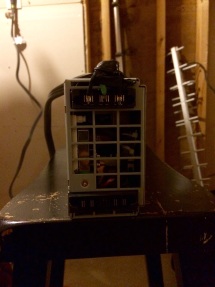
Here is where the steps differ from the W8ZN steps: instead of shorting two pairs of pins together, this power supply requires three in a line to be shorted together. It’s visible in the photo below, I think. The center row.
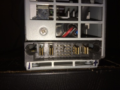
I’m getting 51.4 volts unloaded. Load will be described in the future as it comes to be…
Frog Transceiver
You will have doubtlessly heard about the super cheap Pixie QRP TXRX. Well for those feeling a little flush there is a (and always has been) a real high powered alternative knocking about on eBay. The Frog Transceiver is around the £8 mark at the moment and will give you about 1.5w on 40m and an evenings worth of fun putting it together.
 I’m off work this week for my summer hols and in between kayaking on the sea, being eaten alive in Ennerdale by voracious midges (my own fault for going there when there was no wind and not taking any insect repellent) I’d planned on assembling this little friend to add to my growing collection (along with the Pixie).
The PCB is as one would expect, not bad but not brilliant, components are fit for purpose but the packaging was a little shabby with everything just thrown in a bag, not much protection for the IC’s. So I’m getting my excuses in early….this might not work!
Still £8 is less than an evening at the pub, less than a trip to the cinema (for one) but more than a Pixie 
Our Amazing Sun and HF Radio Signal Propagation
Space Weather. The Sun-Earth Connection. Ionospheric radio propagation. Solar storms. Coronal Mass Ejections (CMEs). Solar flares and radio blackouts. All of these topics are interrelated for the amateur radio operator, especially when the activity involves the shortwave, or high-frequency, radiowave spectrum.
Learning about space weather and radio signal propagation via the ionosphere aids you in gaining a competitive edge in radio DX contests. Want to forecast the radio propagation for the next weekend so you know whether or not you should attend to the Honey-do list, or declare a radio day?
In the last ten years, amazing technological advances have been made in heliophysics research and solar observation. These advances have catapulted the amateur radio hobbyist into a new era in which computer power and easy access to huge amounts of data assist in learning about, observing, and forecasting space weather and to gain an understanding of how space weather impacts shortwave radio propagation, aurora propagation, and so on.
I hope to start “blogging” here about space weather and the propagation of radio waves, as time allows. I hope this finds a place in your journey of exploring the Sun-Earth connection and the science of radio communication.
With that in mind, I’d like to share some pretty cool science. Even though the video material in this article are from 2010, they provide a view of our Sun with the stunning solar tsunami event:
On August 1, 2010, the entire Earth-facing side of the sun erupted in a tumult of activity. There was a C3-class solar flare, a solar tsunami, multiple plasma-filled filaments of magnetism lifting off the stellar surface, large-scale shaking of the solar corona, radio bursts, a coronal mass ejection and more!
At approximately 0855 UTC on August 1, 2010, a C3.2 magnitude soft X-ray flare erupted from NOAA Active Sunspot Region 11092 (we typically shorten this by dropping the first digit: NOAA AR 1092).
At nearly the same time, a massive filament eruption occurred. Prior to the filament’s eruption, NASA’s Solar Dynamics Observatory (SDO) AIA instruments revealed an enormous plasma filament stretching across the sun’s northern hemisphere. When the solar shock wave triggered by the C3.2-class X-ray explosion plowed through this filament, it caused the filament to erupt, sending out a huge plasma cloud.
In this movie, taken by SDO AIA at several different Extreme Ultra Violet (EUV) wavelengths such as the 304- and 171-Angstrom wavelengths, a cooler shock wave can be seen emerging from the origin of the X-ray flare and sweeping across the Sun’s northern hemisphere into the filament field. The impact of this shock wave may propelled the filament into space.
This movie seems to support this analysis: Despite the approximately 400,000 kilometer distance between the flare and the filament eruption, they appear to erupt together. How can this be? Most likely they’re connected by long-range magnetic fields (remember: we cannot see these magnetic field lines unless there is plasma riding these fields).
In the following video clip, taken by SDO AIA at the 304-Angstrom wavelength, a cooler shock wave can be seen emerging from the origin of the X-ray flare and sweeping across the sun’s northern hemisphere into the filament field. The impact of this shock wave propelled the filament into space. This is in black and white because we’re capturing the EUV at the 304-Angstrom wavelength, which we cannot see. SDO does add artificial color to these images, but the raw footage is in this non-colorized view.
The followling video shows this event in the 171-Angstrom wavelength, and highlights more of the flare event:
The following related video shows the “resulting” shock wave several days later. Note that this did NOT result in anything more than a bit of aurora seen by folks living in high-latitude areas (like Norway, for instance).
This fourth video sequence (of the five in the first video shown in this article) shows a simulation model of real-time passage of the solar wind. In this segment, the plasma cloud that was ejected from this solar tsunami event is seen in the data and simulation, passing by Earth and impacting the magnetosphere. This results in the disturbance of the geomagnetic field, triggering aurora and ionospheric depressions that degrade shortwave radio wave propagation.
At about 2/3rd of the way through, UTC time stamp 1651 UTC, the shock wave hits the magnetosphere.
This is a simulation derived from satellite data of the interaction between the solar wind, the earth’s magnetosphere, and earth’s ionosphere. This triggered aurora on August 4, 2010, as the geomagnetic field became stormy (Kp was at or above 5).
While this is an amazing event, a complex series of eruptions involving most of the visible surface of the sun occurred, ejecting plasma toward the Earth, the energy that was transferred by the plasma mass that was ejected by the two eruptions (first, the slower-moving coronal mass ejection originating in the C-class X-ray flare at sunspot region 1092, and, second, the faster-moving plasma ejection originating in the filament eruption) was “moderate.” This event, especially in relationship with the Earth through the Sun-Earth connection, was rather low in energy. It did not result in any news-worthy events on Earth–no laptops were fried, no power grids failed, and the geomagnetic activity level was only moderate, with limited degradation observed on the shortwave radio spectrum.
This “Solar Tsunami” is actually categorized as a “Moreton wave”, the chromospheric signature of a large-scale solar coronal shock wave. As can be seen in this video, they are generated by solar flares. They are named for American astronomer, Gail Moreton, an observer at the Lockheed Solar Observatory in Burbank who spotted them in 1959. He discovered them in time-lapse photography of the chromosphere in the light of the Balmer alpha transition.
Moreton waves propagate at a speed of 250 to 1500 km/s (kilometers per second). A solar scientist, Yutaka Uchida, has interpreted Moreton waves as MHD fast-mode shock waves propagating in the corona. He links them to type II radio bursts, which are radio-wave discharges created when coronal mass ejections accelerate shocks.
I will be posting more of these kinds of posts, some of them explaining the interaction between space weather and the propagation of radio signals.
For live space weather and radio propagation, visit http://SunSpotWatch.com/. Be sure to subscribe to my YouTube channel: https://YouTube.com/NW7US.
The fourth video segment is used by written permission, granted to NW7US by NICT. The movie is copyright@NICT, Japan. The rest of the video is courtesy of SDO/AIA and NASA. Music is courtesy of YouTube, from their free-to-use music library. Video copyright, 2015, by Tomas Hood / NW7US. All rights reserved.
Stunning Video of the Sun Over Five Years, by SDO
Watch this video on a large screen. (It is HD). Discuss. Share.
This video features stunning clips of the Sun, captured by SDO from each of the five years since SDO’s deployment in 2010. In this movie, watch giant clouds of solar material hurled out into space, the dance of giant loops hovering in the corona, and huge sunspots growing and shrinking on the Sun’s surface.
April 21, 2015 marks the five-year anniversary of the Solar Dynamics Observatory (SDO) First Light press conference, where NASA revealed the first images taken by the spacecraft. Since then, SDO has captured amazingly stunning super-high-definition images in multiple wavelengths, revealing new science, and captivating views.
February 11, 2015 marks five years in space for NASA’s Solar Dynamics Observatory, which provides incredibly detailed images of the whole Sun 24 hours a day. February 11, 2010, was the day on which NASA launched an unprecedented solar observatory into space. The Solar Dynamics Observatory (SDO) flew up on an Atlas V rocket, carrying instruments that scientists hoped would revolutionize observations of the Sun.
Capturing an image more than once per second, SDO has provided an unprecedentedly clear picture of how massive explosions on the Sun grow and erupt. The imagery is also captivating, allowing one to watch the constant ballet of solar material through the sun’s atmosphere, the corona.
The imagery in this “highlight reel” provide us with examples of the kind of data that SDO provides to scientists. By watching the sun in different wavelengths (and therefore different temperatures, each “seen” at a particular wavelength that is invisible to the unaided eye) scientists can watch how material courses through the corona. SDO captures images of the Sun in 10 different wavelengths, each of which helps highlight a different temperature of solar material. Different temperatures can, in turn, show specific structures on the Sun such as solar flares or coronal loops, and help reveal what causes eruptions on the Sun, what heats the Sun’s atmosphere up to 1,000 times hotter than its surface, and why the Sun’s magnetic fields are constantly on the move.
Coronal loops are streams of solar material traveling up and down looping magnetic field lines). Solar flares are bursts of light, energy and X-rays. They can occur by themselves or can be accompanied by what’s called a coronal mass ejection, or CME, in which a giant cloud of solar material erupts off the Sun, achieves escape velocity and heads off into space.
This movie shows examples of x-ray flares, coronal mass ejections, prominence eruptions when masses of solar material leap off the Sun, much like CMEs. The movie also shows sunspot groups on the solar surface. One of these sunspot groups, a magnetically strong and complex region appearing in mid-January 2014, was one of the largest in nine years as well as a torrent of intense solar flares. In this case, the Sun produced only flares and no CMEs, which, while not unheard of, is somewhat unusual for flares of that size. Scientists are looking at that data now to see if they can determine what circumstances might have led to flares eruptions alone.
Scientists study these images to better understand the complex electromagnetic system causing the constant movement on the sun, which can ultimately have an effect closer to Earth, too: Flares and another type of solar explosion called coronal mass ejections can sometimes disrupt technology in space as well as on Earth (disrupting shortwave communication, stressing power grids, and more). Additionally, studying our closest star is one way of learning about other stars in the galaxy.
Goddard built, operates and manages the SDO spacecraft for NASA’s Science Mission Directorate in Washington, D.C. SDO is the first mission of NASA’s Living with a Star Program. The program’s goal is to develop the scientific understanding necessary to address those aspects of the sun-Earth system that directly affect our lives and society.