Archive for the ‘radio’ Category
 What is the big deal with amateur radio? What is it that you hear? (Part 1)

Shortwave radio has been a source for great sci-fi plots, spy intrigue novels, movies, and so on, since radio first became a “thing.” But, what is the big deal, really? What is it that amateur radio operators listen to?
In this video, I share some of the types of signals one might hear on the high frequencies (also known as shortwave or HF bands). This is the first video in an on-going series introducing amateur radio to the interested hobbyist, prepper, and informed citizen.
I often am asked by preppers, makers, and other hobbyists, who’ve not yet been introduced to the world of amateur radio and shortwave radio: “Just what do you amateur radio operators hear, on the amateur radio shortwave bands?”
To begin answering that question, I’ve taken a few moments on video, to share from my perspective, a bit about this shortwave radio thing:
Link to video: https://youtu.be/pIVesUzNP2U — please share with your non-ham friends.
From my shortwave website:
Shortwave Radio Listening — listen to the World on a radio, wherever you might be. Shortwave Radio is similar to the local AM Broadcast Band on Mediumwave (MW) that you can hear on a regular “AM Radio” receiver, except that shortwave signals travel globally, depending on the time of day, time of year, and space weather conditions.
The International Shortwave Broadcasters transmit their signals in various bands of shortwave radio spectrum, found in the 2.3 MHz to 30.0 MHz range. You might think that you need expensive equipment to receive these international broadcasts, but you don’t! Unlike new Satellite services, Shortwave Radio (which has been around since the beginning of the radio era) can work anywhere with very affordable radio equipment. All that you need to hear these signals from around the World is a radio which can receive frequencies in the shortwave bands. Such radios can be very affordable. Of course, you get what you pay for; if you find that this hobby sparks your interest, you might consider more advanced radio equipment. But you would be surprised by how much you can hear with entry-level shortwave receivers. (You’ll see some of these radios on this page).
You do not need a special antenna, though the better the antenna used, the better you can hear weaker stations. You can use the telescopic antenna found on many of the portable shortwave radios now available. However, for reception of more exotic international broadcasts, you should attach a length of wire to your radio’s antenna or antenna jack.
Get crackalackin’
As Fall is here, it is time to put together a To Do list of everything I have been putting off all Summer and the beginning of the school year.
TM-D710A

I have four of these rigs and they need some TLC. I need to make sure they have the updated firmware on the main unit, TNC, and operating panel.
The latest versions:
TNC: 1.02 – May 2011
Operating Panel: 2.12 – Janurary 2015
Main unit: 2.10 – May 2011
For the benifit of emergency operations, I have been performing the modificiation to the TM-D710As to open the frequency range.
Standard frequency plan. I developed a spreadsheet of the repeaters in the greater Kansas City area, frequecies for FRS/GMRS, the Kansas City Airport (MCI), Sherman Army Airfield, and various national park frequency plans. This is the first step in standardizing the configuration across all four of the TM-D710As. I can additionally take the spreadsheet and use it for programming my HTs. This should allow for a memory channel standardization that will make my life easier.
Weather Station

The current Davis Vantage Pro2 I have installed on the roof needs maintenance. Wouldn’t it be nice to get the top of the line version?
For some time I have been talking about finding a weather station setup that will work with a linux-based computer. That quest continues. I have read about a piece of software called Meteo that is suppose to work with Xastir.
And if I can’t get Xastir to work with the Vantage Pro2… is there another comparable weather station that WILL work with Xastir? Life would be a lot easier without Windows.
HF Antenna for home
I need to string up the Carolina Windom I have had sitting on the shelf for the last few years. The G5RV that is up now is showing its age (not to mention one of the legs is drooping badly). Now that the leaves have fallen, I should be able to get the Windom up there without too many problems (… famous last words).
HF setup in the mobile
Time to get going. I have all the materials I need. What I don’t have is an installation plan… mainly for the Tarheel antenna. I can’t do a hitch mount because I need the hitch for pulling my travel trailer. Two possible options: (a) get a swinging gate for the back bumper where you could mount a spare tire and a water can or (b) find some way to afix a mount coming out behind the left rear tire.
Autumn = projects time
I usually cycle to work. Wow I hear you say, what a guy….Well thanks but I hadn’t finished the introduction. Cycling means you notice the seasons a lot more than if you drive. Its still the season for shorts and after some very mild days we’re definitely heading towards fully developed autumn. So what?
Well its time to spend fewer hours outside (because you’ll be blown across the street) and more time preparing for those murky days when projects are preferable to souwesters.
This year I have got a couple of PCB’s that need populating. 1 of them is the Budd Churchward Morseduino. The other is the Minima Transceiver.
Budd created a neat little barebones arduino and morse code decoder and he kindly gave me the gerbers. It is essentially a very simple device that will allow audio to pass through and it will give a reasonable decode of CW. I say reasonable because it is never going to be as good as your purists ears but it’ll help get the less talented on the air (hopefully). This video gives you a flavour
Project 2 it the Minima Transceiver, by Ashran Farhan of BitX fame. It is my first foray into complete rig build for the experimenter so I’m expecting some tinker time. Essentially it is a Arduino controlled simple transceiver (Any spot the link here?). This will be a lot more involved and I’m just getting my head around the schematic.
There seems to be a lot of useful information about so if I get stuck then google will no doubt be my friend! Here’s a little taster.
Toyota Transition
This blog started in conjunction with my return to the United States in 2005 and purchase of a Toyota Tundra. After being away from the US for four years, I celebrated my return by the purchase of the new truck and a (mostly) circumnavigation of the lower 48. My first encounter with Toyota was through my friend Robb and a 1980s Toyota 4×4 he had. Robb was going to school at Cal Poly, San Luis Obispo. Robb was fond of taking his truck to Pismo Beach and enjoying the beach and dune experience. Robb loved his truck.
After spending a year in Monterrey, CA learning Russian at the Defense Language Institute and a few months honing my listening abilities at Goodfellow Air Force Base near San Angelo, TX, I got my follow on orders to Fairbanks, Alaska (Fort Wainwright). I didn’t have a car. I was an enlisted Army soldier making not a whole lot of money. Heading way, way up north. I figured I needed a 4-wheel drive vehicle to make my life a bit more comfortable. My first thought was a Ford Ranger. But it ended up being too expensive. The most reasonable costing 4-wheel drive vehicle was a Toyota 4×4. It was 1993 and the Tacoma had not come along yet. 1993 Toyota 4×4. Manual locking hubs. Manual windows. AM/FM radio. Bench seat. No A/C. 4 cylinders. That truck was to go on to perform flawlessly in Alaska, transported me from Alaska to Georgia and several cross-country trips. Arizona. Washington State. Texas. And California. For seven years, that truck never let me down. I was heading off to Korea for a year to be followed by three in Germany. I sold the truck.


When I was planning my return to the US, I knew I wanted to get another Toyota. I settled on the Tundra. But instead of the minimum package, I was able to swing a 2005 Toyota Tundra Limited Double Cab 4×4. This truck offered to support a newly forming family. I broke the truck in with a trip around the US. I continually upgraded my ham radio installation in the truck, further enhancing my mobile enjoyment. The Tundra performed flawlessly. Never an issue.


The Tundra proved to be the hero of the 2015 Summer trip. Five national parks. From Kansas to Montana, Wyoming, out to California and back. Pulling a travel trailer. No issues, no problems. Over 120,000 miles.

It was time to think about the future. A future of summer travel. Exploration of national parks in the west. Colorado. Arizona. Utah. Maybe an upgrade to the travel trailer. The 2005 Tundra had an older drive train and a towing capacity topping out at 4,200 lbs. Comparing the aging 2005 Tundra to the current available 4x4s… the 2005 had a hard time measuring up.
I wanted to find something that was as reliable and dependable. Offered increase towing capability. But maybe smaller? Truth be told, I often had difficulty parking the Tundra. The turning radius was… challenging. Was there something available in a smaller package, yet offering increased performance and towing capabilities? Oh… did I mention that it has to be a Toyota?
Creating open-source ham radio hardware with Kickstarter
When I started my company last year, it was mainly set up as a design consulting outfit to pick up a few jobs on the side. At the end of 2014, it became much more when I decided to plunge full-time into my own work. At the time, one of my respected friends and colleagues, Don Powrie of DLP Design, said to me that the only way to make consistent money is to have a product line rather than rely on consulting work. I’ve been thinking of how to bring that to market ever since. I could certainly design some familiar products to me, but they would get lost in the plethora of similar items. I needed something unique.

I started out with a 5V @ 5A design. I drew the schematic and completed the PCB layout and started to check pricing and availability of the parts. Most everything was available at Digi-Key, and the Anderson Connectors from Mouser, but the total was getting close to where I wanted the selling price to be. For a $35 computer, I couldn’t justify a $70-$80 power board!! The DC-DC converter also had a very large ground pad for heat dissipation. I wanted this project to be able to be hand-soldered and started wondering about that large pad. That design got scrapped and I started looking for another buck converter. There were several TI and Linear products I considered, but they would have required a reflow oven – either with a center pad, as a BGA, or leadless formats. Then I found the Alpha & Omega AOZ1031AI. This is a 8-pin SOIC without any special pad. The only heat-dissipation suggestion was that pins 7 and 8 do not have any thermal relief, but connect fully to the surrounding plane. I selected larger commodity parts (0805) that could be seen without a microscope and created the layout, and all parts were in stock at either Digi-Key or Mouser Electronics. I got everything on order, and even managed to get a couple free PCBs from Pentalogix. I had attended a Pentalogix-sponsored Cadsoft Eagle webinar at Newark and the perk was a code for two boards. I just had to cover shipping.
I did other tests: Let it run for 8 hours (check), ramp voltage from 6 to 18V input (check). At 7V input, the Pi kept rebooting. At 8V, it was solid – well past the design spec. Same at 18V.
Next up was the load test. With 2A going direct to load resistors, I was still able to run the Pi with all four USB ports occupied. I even dipped the supply to 8V. The bench supply showed about 1.8A output. Based on an approximate 80% efficiency of DC-DC converter, I calculated I was drawing about 3.5A on the 5V side – a little past its limit, so backed off the load. I’ve been running this directly from my radio supply now for several days, and the Pi keeps chugging along.

I’m a believer in open-source hardware and software. This project will be published in the coming days, probably on GitHub. Eagle uses XML design files, so version control should work just fine. I still need to write the manual, but everything will be made available as soon as I get the proper README and LICENSE files in place. All of my work for this project is published under the Creative Commons Attribution and Share-Alike license. The hardware itself is published under the TAPR Open Hardware License.
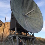
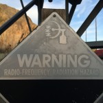
July Greenland Trip
Made a quick trip to Greenland for three days in July to work on some equipment there. I did not get on the air due to work activities and operation of the incoherent scatter radar whose modulator trashes the HF bands if you’re close to it (i.e., same building). A few photos, though. These were all shot with an iPhone 5s, nothing fancy.


50-MHz transverter update (Psst! Newark has cheap 22-MHz crystals)
A few years ago, I built a 50-MHz transverter to operate 6m with my Kenwood TS-930Ses. I subsequently replaced the two 930s with an Elecraft K3/100 and Elecraft K2/100. The K3 has 6m and I sold off my TS-700S (and my 6m Mirage brick amplifier) to help finance the internal 2m board for the K3. The problem with this arrangement is that I can’t be on 6m and 2m at the same time. I recently assembled and added the SSB board and transverter interface to my K2 (no time to blog about this but they were straightforward additions like everything from Elecraft), now making it an attractive IF for the 6m transverter (and the Microwave Modules 432 transverter I have on the shelf and the 222-MHz transverter I plan to build sometime).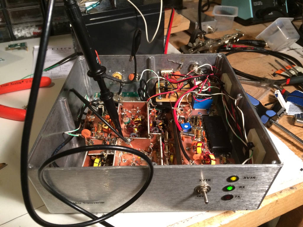
Enter the problem: Because I was thrifty about building the transverter at first, I had used an inexpensive and widely-available 24-MHz crystal for a 26-MHz IF. The TS-930S happily worked here (by the way, pro-tip: A lot of guys say that they liked to have the wideband transmit mods on their HF rigs so they could have a wideband signal source for testing/transverters/etc. The TS-930S will give you a low-level TX out anywhere through the transverter port, even if you don’t have the mod. Well, at least my PIEXX-equipped 930 did). However, the K2 only allows a select set of transverter IF bands to be used natively. Good fortune shone upon my endeavors when I did a quick Google search for 22-MHz crystals and one actually popped up at Newark/Element14 (part number is 86R1720, get ‘em while they’re hot)! Even better news was that it was on closeout for 12 cents apiece! I splurged and bought five, along with some other parts for another project or two I’ll post about eventually.
I carefully peeled back a layer of dead-bug components, extracted the 24-MHz crystal, and replaced it with the new 22-MHz variety, sacrificing only one 4.7-k resistor, an easily-replaced stock item at K8GU. The LO came up about 5.4 kHz low and I couldn’t peak it any higher. So, I’ll either have to futz around with the loading of the crystal or (more likely) load an offset in the K2’s transverter band entry for 6m.
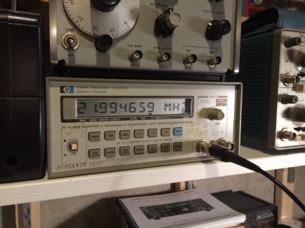
The local W3APL beacon popped up at 28.0694 MHz, which is consistent with the offset I observed above. Now, I just have to get the other interfacing juju worked out to get the K2 to properly command the transverter to transmit and feed it the proper drive level.


