Archive for the ‘ham radio’ Category
 Slacker SOTA Activation in the Tetons (W7Y/TT-061)
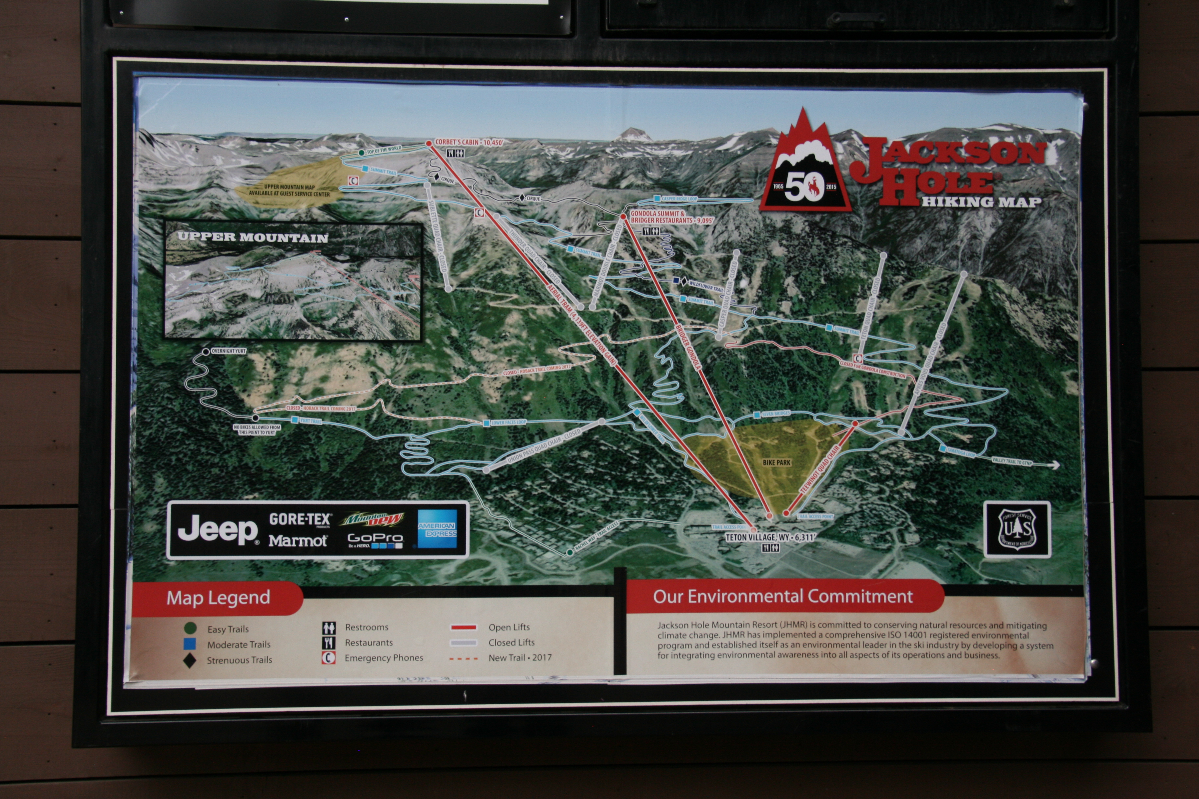
The Grand Teton National Park has plenty of mountains for Summits On The Air (SOTA) activations, so I wanted to activate a few of them as we enjoyed the park. I am still recovering from a fractured ankle, so I was definitely looking for an easy-peasy summit to activate on our trip. It turns out there is a summit right at the top of the Jackson Hole Arial Tram that operates during the summer months (W7Y/TT-061). (This tram serves the ski area during the winter.)
The SOTA database shows this summit as unnamed and refers to it by elevation, 10450. The locals may refer to this as Rendezvous Mountain, not to be confused with Rendezvous Peak (W7Y/TT-035). For SOTA purposes its just “10450”.
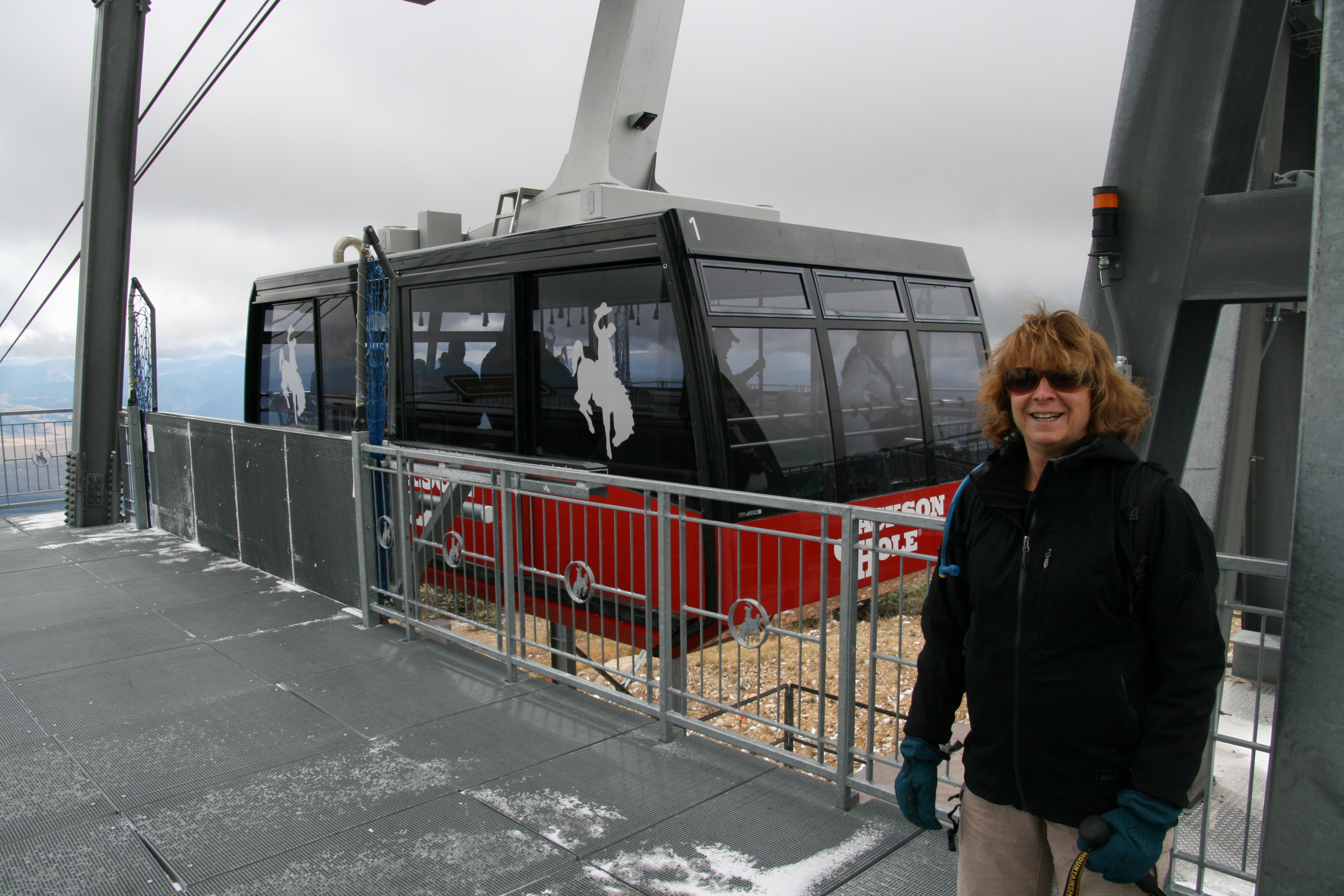
Well, this sounds pretty awesome…ride the tram to the top and play ham radio. Now the bad news: the ticket for the tram is $42. It’s an all day pass that gives you access to other lifts and plenty of hiking trails but still it is expensive. OK, slightly better news: if you purchase online you can get the pass for $32. There are senior and other pricing options, so check out the web site for the latest info.
The September weather was overcast and cold at the summit. I opted for a simple VHF activation using my Yaesu FT-1DR and a half-wave vertical antenna. I had my 3-element 2m yagi with me but I didn’t deploy it. I figured that my ability to contact folks on 2m fm would be limited more by who happens to be monitoring…signal strength would not be a major factor.
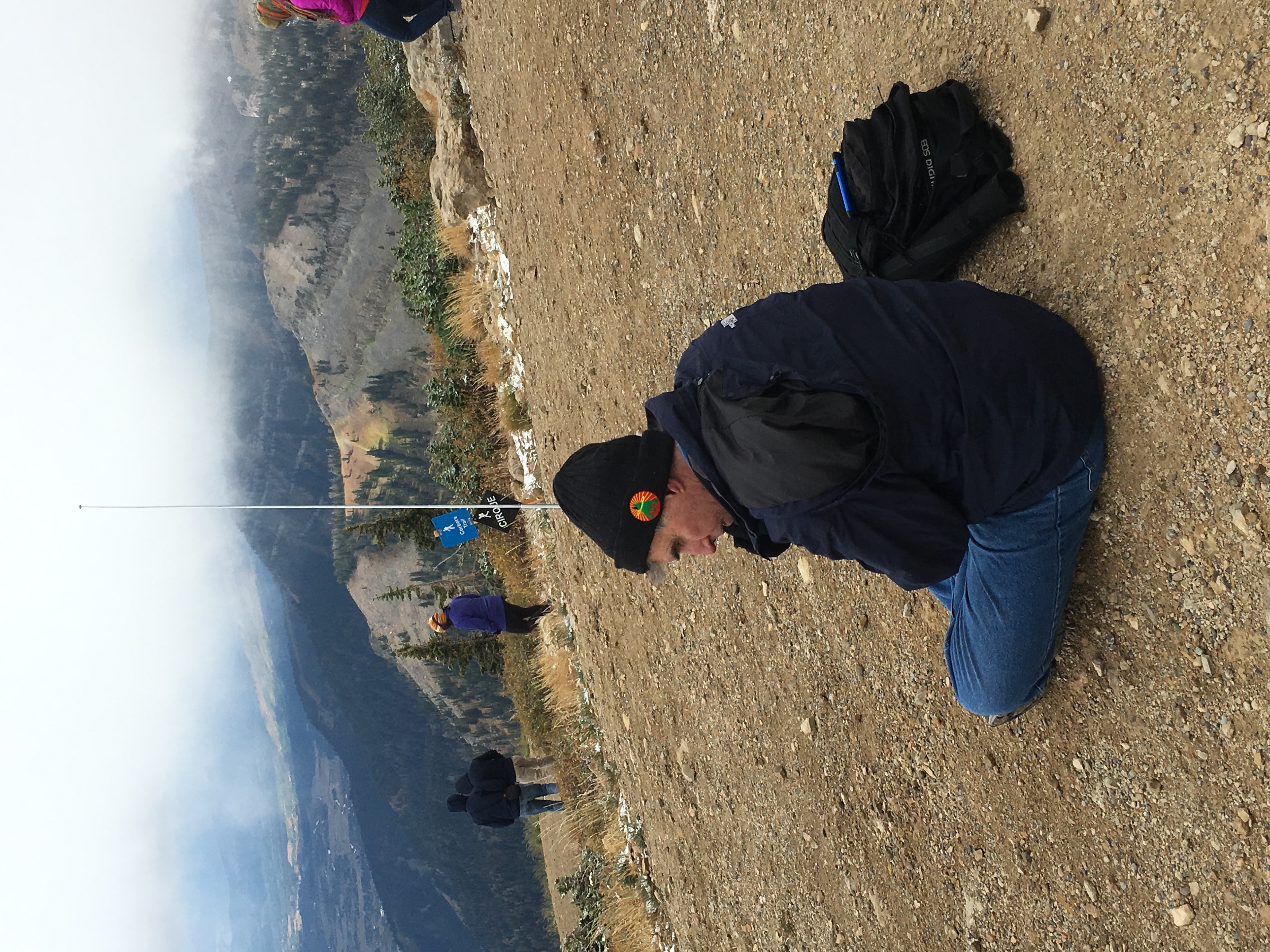
It was cold at the top and I was glad that I packed my gloves, hat and a decent jacket. I made five contacts by calling on 146.52 MHz.
The tram ride was quite enjoyable with good views of the Jackson Hole area. However, this may go down in history as my most expensive SOTA activation.
73, Bob K0NR
The post Slacker SOTA Activation in the Tetons (W7Y/TT-061) appeared first on The KØNR Radio Site.
General License Class (Black Forest, CO)
 Ham Radio General License
Two-day Class
Black Forest, Colorado
Two class sessions on Sat Sept 24 and Sat Oct 1 (8 AM to 5 PM) FCC Exam session on Oct 8th
Location: Black Forest Fire Station
Intersection of Burgess Rd. & Teachout Rd.
The General License provides access to regional and worldwide communications on the HF bands via ionospheric skip, greatly expanding operational capabilities!
- Upgrade from Technician to General Class radio privileges
- Pass your FCC General Class amateur license exam Oct 8 *
- Live equipment demonstrations and activities
- Learn to operate on the HF bands, 10 Meters to 160 Meters
- Gain a deeper understanding of radio electronics and theory
- Take the next step with antennas, amplifiers, digital modes
Registration fee: $30
(No FCC exam fee required at Oct 8 exam session)
In addition, students must have the required study guide:
HamRadioSchool.com General License Course
Second Edition, effective 2015 – 2019, $22.95
Current FCC Technician License required for registration. Advanced registration is required by Sept 10th or earlier. First-come registration acceptance until class is full.
To register for the class, contact: Bob Witte KØNR
Email: [email protected] or Phone: 719/659-3727
Sponsored by the Tri-Lakes Monument Radio Association.
The post General License Class (Black Forest, CO) appeared first on The KØNR Radio Site.
Don’t Pound My Octothorpe
 If you want to spark a conversation at your next social event, ask everyone the proper name for this symbol: #. Most North Americans will probably say pound sign or perhaps number sign. It helps to have an international audience, since a person from the UK will likely call it the hash symbol. Lately, the world of Twitter (and other social media) has made extensive use of # to tag keywords, referring to it as the hash mark used to create hashtags. A musician might claim that it is the sharp symbol from musical notation but closer examination reveals that the sharp symbol is quite different.
The AT&T engineers working on the original DTMF system adopted the name Octothorpe for this symbol. There are various explanations and anecdotes that have developed over the years concerning how this happened. Various forms of spelling show up in the literature (octatherp, octothorp, etc.). Doug Kerr’s story is particularly interesting and available on the internet (see below). There are US Patents that use the word “octothorp” to refer to the # symbol. Patent number 3920926 uses “octothorp” for # and “sextile or asterisk” for the * symbol. The term sextile never caught on at all.
For amateur radio usage (North America bias), I hear mostly pound for # and star for *. I suspect that will not change any time soon.
– Bob K0NR
Wikipedia entry for the number sign (#): http://en.wikipedia.org/wiki/Number_sign
The Symbol on the “Pound” or “Number” Key (#) is Also Called an Octothorpe
The ASCII Character “Octatherp”, by Doug Kerr
The post Don’t Pound My Octothorpe appeared first on The KØNR Radio Site.
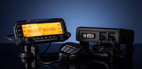
Review – BTech UV-5X3 TriBand Handheld
 UV-5X3
Although the case design is familiar, the radio inside is not. BTech has recently introduced the new UV-5X3 to the US Ham Radio market. This radio is a true triband transceiver with internal filters specifically configured for triband operation.The firmware in this radio has been reworked to include several new features not found in similar appearing radios.
.
In the Box
Included with the radio are the:
– 1500mAh Li-Ion Battery **
– 85 page User Guide – English
– Charger base & AC adapter
– Hand strap
– Belt clip
– PTT Earpiece / Microphone
– Antenna (1) – VHF / UHF 6 3/4″ (17cm) A-V85
– Antenna (2) – 220 MHz 6 1/4″ (15.5cm)
.
** This is the identical battery that is commonly mislabeled as 1800mAh on some handhelds.
The UV-5X3 was specifically designed as a Tri-Band transceiver. The internal filtering allows not only the traditional VHF and UHF frequencies, but also includes the 222-225 MHz Ham band for the US.
 Case Design
The UV-5X3 has the traditional case design, which allows me to use my high capacity BL-5L 3800mAh battery with no alteration to the base. Accessories such as my mobile battery eliminator, Spkr/Micr, etc. are fully compatible.
.
Transmitter
The frequency range is VHF 130-176 / 222-225 / UHF 400-480 MHz, supporting both Wide and Narrowband with 2.5kHz steps.The radio’s filtering scheme allows for full power on all bands. My OTA audio reports have been clean with clear with mellow audio. Power levels are respectable using a Bird VHF/UHF Termaline.
|
DTMF / IRLP Access
Something new also appearing on this model is a DTMF gain adjustment, allowing me to adjust the DTMF audio to the transmitter to a comfortable level for both repeater control and IRLP access.
If you are in a area that requires tone burst for repeater or network access, the 1000Hz, 1450Hz, 1750Hz, and 2000Hz burst are accessible by pressing the PTT along with one of the four pre-assigned keypad keys.
The receiver sensitivity is excellent, and the audio quality is clear, loud, and undistorted. Along with the 3 TX/RX bands, the receiver also includes the traditional commercial FM radio band. (65MHz-108MHz)
.
Tone Scanning – The receiver also has the ability to identify the tone of a repeater being transmitted by a received signal.
This feature gives me the ability to add / delete channels from the scanning list using the keypad. No longer a software only function. The more I can do from the keypad, the better I like it.
A Long Press of the [*SCN] button will start the scanning process.Channel Mode – When scanning with the Display Sync set to ON, the upper and lower display will scan together. This is explained below under Display Synchronization.Frequency Mode – When entering Scan, the image below will appear on the screen. Enter the first 3 digits set the range start, the second 3 digits sets the stop.
Example: Entering 146 : 146
Start the scan range at 146.000
Ends the scan range at 146.999
 Antenna
I found two antennas included with the radio. One was the standard upgraded A-V85 antenna, and a slightly shorter one for the 220MHz band.
Antenna (1) – VHF / UHF 6 3/4″ (17cm) A-V85
Antenna (2) – 220 MHz 6 1/4″ (15.5cm)
The separate antenna specifically tuned for 220 MHz is a great addition. The SWR shows 1.3 which is excellent. No compromise. I labeled my 220 antenna, as they are very close in appearance.
Display
The radio has a tri-color display, allowing the color options of the blue, orange and purple. The LCD can be formatted in either of three formats. Choices are Frequency, Channel number, or up to 6 Alpha Characters.Display Synchronization
The UV-5X3 supports display syncing, which gives ability to track both the upper and lower LCD. I keep mine set to display the channel name in display A, and the frequency in display B. When you change the channel, both the upper and lower displays move together.
 .
.Programming
Manual programming is pretty straight forward once you enter a few channels. A programming guide can be found at Manual Programming with a Menu Definition summary available at Menu Definitions.
The software support for the UV-5X3 can be found in the Latest Daily Build of CHIRP. There are a few new options that will be added to the 5X3 in the near future. One is the ability to Stun, Kill, Revive. This gives you the ability to disable your radio remotely.
The new chipset (RDA1846S and RDA5802N) provides reduced AGC switching noise and a low-IF digital audio processor for improved sound quality.
The programming cable requires a traditional two pin Baofeng / Kenwood style. There are several cable available. The generic cables may require special drivers, due to the use of cloned chips. For Plug and Play, a cable using an FTDI chip is recommended.
 Conclusion
The UV-5X3 firmware has obviously been reworked to include:
– Tri-Band Support: VHF/1.25M/UHF
– D-ANI (Display incoming DTMF Tones)
– Synchronized Displays
– DTMF audio gain level adjustment
– Add / Remove Channels from Scanning list via keypad (LCD Dot Indication)
– On the Fly scanning by Frequency Range
– 4 Tone Burst options
– Remote Stun, Kill, Revive

Monarch Ridge South SOTA Activation (W0C/SP-058)
For the 2016 Colorado 14er Event, I had to choose really easy SOTA summits to activate because I had fractured my ankle earlier in the summer. At this point, I was able to hobble around with a protective boot but walking more than a few hundred feet was difficult. On Saturday, we drove up Pikes Peak and took a short stroll away from the vehicle to operate. On Sunday, we decided to activate Monarch Ridge South (W0C/SP-058), using the sight-seeing tram that goes to the top.
 Access is right off Monarch Pass (Hwy 50), where there is a large parking lot. There is a trail that goes to the top and we’ll be back to hike that some other time. (Actually, Joyce K0JJW and I already tried to snowshoe to the top in blizzard conditions but that is another story for another day.) The trail is a popular mountain bike route, so we saw lots of bikers in the parking lot unloading gear. Monarch Pass is oriented north/south and the trail heads off to the east (behind the tram building).
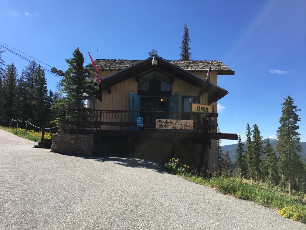 The tram boarding location is inside this building at the bottom of the tram. We purchased tickets in the nearby gift shop, which is worth a look if you need a map, book, ice cream cone or trinkets. See their website for latest schedule and pricing.
 Here’s a photo of the tram going up the side of the mountain. Of course, the views are great and the ride takes about 10 minutes. The tram car holds four people and a reasonable amount of SOTA gear.
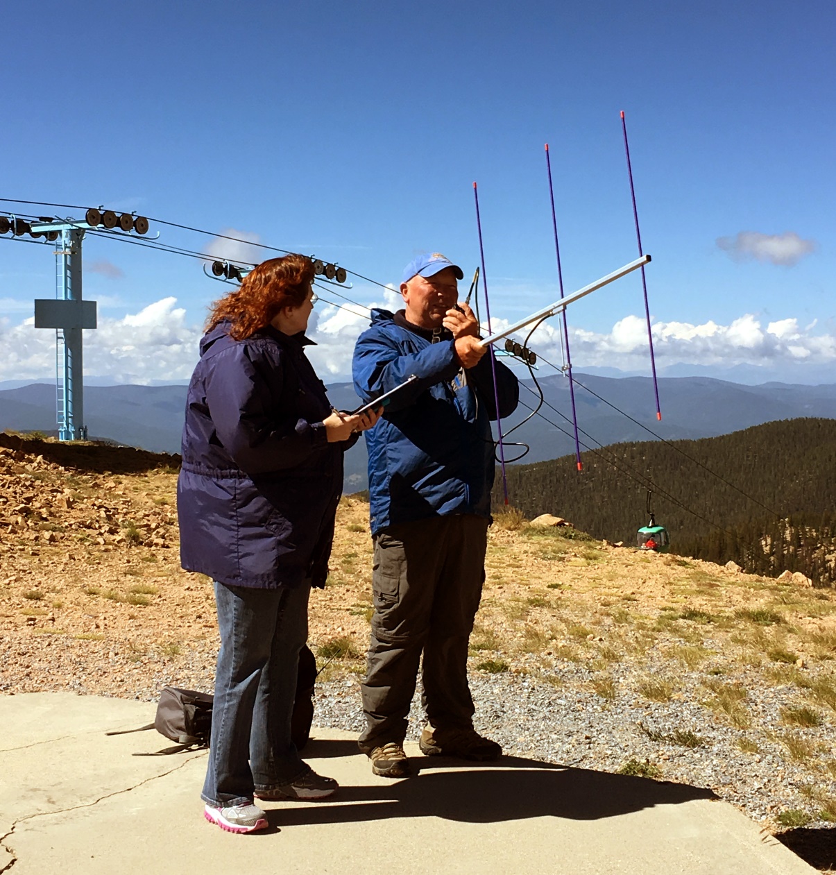 At the top, Denny KB9DPF made contacts on 2m FM, aided by expert logger Kathy KB9GVC. The actual summit is a ways to the south of the tram, maybe a tenth of a mile, but we operated from a concrete pad on the north side. The ridge is flat and we judged the activation area to be very large.
We made a total of 13 contacts on 2m and 70cm, including 5 other SOTA summits (S2S).
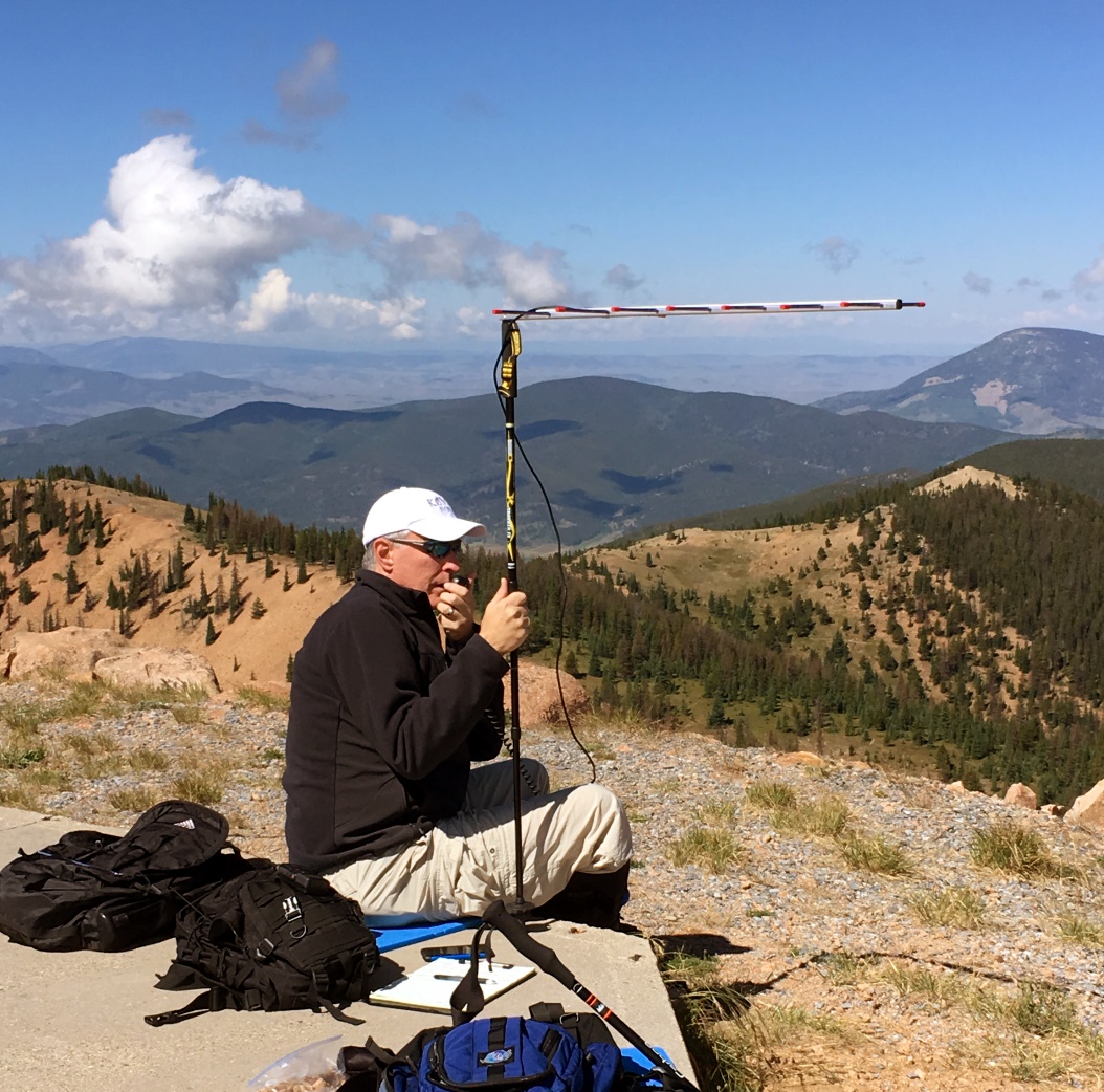 I used my Yaesu FT-817 on 432.100 MHz SSB, hoping to find someone in the UHF contest that is happening concurrently with the 14er event. I didn’t work anyone on 70cm SSB but I did work K3ILC in Colorado Springs on FM at a distance of ~90 miles. Not too bad. The Arrow antenna is attached to my hiking stick via the camera mount thread.
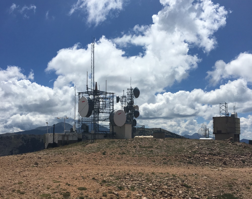 There is a substantial radio site on Monarch Ridge that did provide some RF interference to us on 2 meters. The 70 cm band seemed to be unaffected but I can’t be sure. The “bad boy” transmitter is the KMYP automated weather station (AWOS) transmitting continuously on 124.175 MHz. Well, at least we could receive current weather information. We did relocate to put some distance between us and the transmitters but my lack of mobility kept us from going too far.
If you are looking for an easy access SOTA summit near Monarch Pass with excellent views, this is it. The hike up should not be very difficult but the tram makes it even easier. If you plan to operate 2 meters, expect some interference. Next time, I’ll try locating even further away from the transmitter site. I might even bring along some bandpass filters. Other SOTA enthusiasts have reported no problems on the HF bands.
At the time of this post, there are plans to put a 2m amateur repeater at this site on 145.325 MHz.
73, Bob K0NR
The post Monarch Ridge South SOTA Activation (W0C/SP-058) appeared first on The KØNR Radio Site.
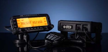
Review – BTech UV-50X3 (Tri-Band)
by John ‘Miklor’
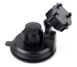
Included with the radio are: 50X3 Weight: Main Chassis 2.1kg (4.6 lbs) Specifications The 50X3 is FCC Part 90 certified for commercial use in the US. Control Head The suction mount is about the best I’ve ever used. It requires a smooth metal or glass surface, but the silicon rubber cup will not let loose. My control head has been mounted atop my computer for over a month, and it is going nowhere. The button functions are displayed on the LCD screen for easy function identification. The PTT button on the upper right is for Momentary or Toggle PTT. One press turns the TX on, next press turns it off. Setting to Toggle is convenient if running a net or using a mobile headset.  Cooling The 220 ham band transmit range is limited to 222-225MHz. The receiver is capable of being programmed above and below those frequencies, but may be outside of the performance range due to the ham band specific filtering.
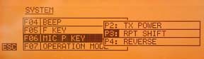
Microphone The radio comes with a full function keypad style microphone. On the right side are two slide switches that control the Lock and Lamp feature, and on top of the microphone are two frequency Up and Down buttons. Along with a 16 button DTMF style keypad are 4 programmable function keys. Choices are Squelch Off, TX Power, Rptr Shift, Reverse, and Tone Call. There are two microphone input jacks. One on the control head, the other on the main unit. There is also a built in microphone element inside the control head. Although the audio quality is excellent, the sensitivity is that of a standard microphone. The OTA reports were excellent with plenty of audio, so there’s no reason to shout. A nice feature in the audio section is an adjustable microphone gain control. There are 5 settings available. Min, Low, Normal, High, and Max. Normal is great for speaking in a normal volume an inch from the microphone. Running a net with VOX and a headset, you can bring it up a bit. Driving in an off road vehicle, you just might need to set it back.
Receiver Along with the standard VHF / 220 / UHF frequencies, the receiver covers: 0.5-1.7 MHz (AM Radio) The control head has built in speakers, as well as one in the main module. An external speaker jack in the rear also allows for a larger speaker if desired. The jack provides for either mono or stereo output. (each receiver can have it’s own speaker). I found a menu setting to adjust the tone of the speaker as well. Although there is more than ample audio output, when the volume control is all the way down, the radio is silent, as it should be. Cross Band Repeat The radio takes full advantage of the independent receiver by including a Cross Band Repeat function. I entered the VHF and UHF frequencies, power level and tones, selected the Cross Band mode, and was ready to go. The audio levels are preset and the audio quality reports were excellent. Cross band repeating using a 220MHz frequency was not possible. This is more than likely a precaution due to the minimal frequency separation. Display The control head has a large 5″ LCD with your choice of background colors. Options include White-Blue, Sky-Blue, Marine-Blue, Green, Yellow-Green, Orange, Amber, and White. The brightness and contrast are also menu selectable.
Unless you are only entering a few channels, I would recommend the optional PC05 programming cable. The UV-50X3 uses the CHIRP programming software. Scanning in the VFO mode allowed me to scan either the VHF, 220MHz, or UHF band. In the Channel mode, the scan would select any channel in the list regardless of band. Power Cable There are radios that draw less power whose power cables use thinner wire, lower value fuses, and can be plugged into accessory plugs. Do NOT use these cables, even though they may be plug compatible. The 50X3 draws twice the current, and will blow the fuses and possibly overheat the wire. The cable on the 50X3 appears to match that of the hi-power Yaesu, Icom, Kenwood series. ONLY use the proper cable for the radio. Base Station Operation For mobile drive testing, I teamed this radio with a Nagoya Tri-Band TB320A and SB-35 NMO mag mount and the results were excellent. Conclusion Some of the added advantages to the US market are the FCC Part 90 certification, local US support, and exclusive program support using CHIRP software. The radio can also be shipped worldwide by contacting BTech directly. This is definitely one of the nicest mobile transceivers I’ve used; and yes, I’ve owned the “big 3”.
More Information: Miklor.com |
 Four years after its initial design, the VGC 6600PRO has evolved into the BTech UV-50X3, a full featured Tri-Band mobile that delivers a full 50W on VHF and UHF, with addition of a 220 MHz module that delivers 5W output. The 220 MHz module was specifically designed and filtered for 222-225MHz US ham band operation. I mention this as there are currently radios being advertised as Tri-Band operating in the range of 240-260MHz that are not adaptable to frequencies below 240MHz due to their internal filtering.


What’s In Your Rubber Duck?
 Anyone with a VHF or UHF handheld transceiver (HT) probably uses the standard “rubber duck” antenna for casual use. I often refer to the rubber duck as The World’s Most Convenient Crappy Antenna. To be fair, all antennas are a compromise…the rubber duck optimizes small size and convenience at the expense of performance. The Wikipedia entry describes the rubber duck antenna as “an electrically short monopole antenna…[that] consists of a springy wire in the shape of a narrow helix, sealed in a rubber or plastic jacket to protect the antenna.“
Being curious about what really is hiding inside the typical rubber duck antenna, I decided to take a few of them apart. I did not try to assess the performance of the antennas but just examine their construction.
Baofeng UV-5R Stock Antenna
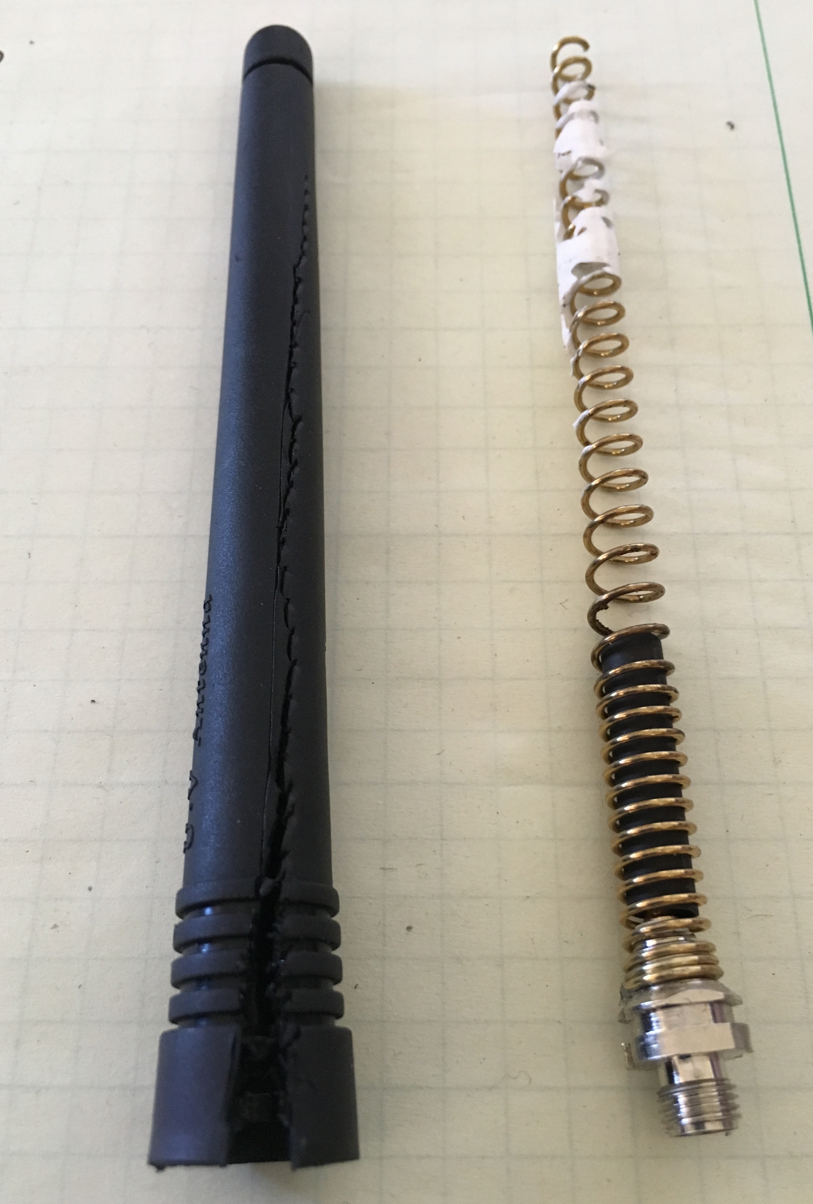
I started by dissecting a Baofeng UV-5R antenna, which took some aggressive action with a diagonal wire cutters to split the rubberized jacket near the bottom. After that, the jacket slid off to reveal the classic spiral antenna element inside. You can see some white adhesive near the top of the spiral element (upper right in the photo).
The Baofeng antenna had a female SMA connector.
Note: You can access high resolution versions of the photos in this article by clicking on them, allowing you to see lots of detail.
Yaesu FT-1DR Stock Antenna
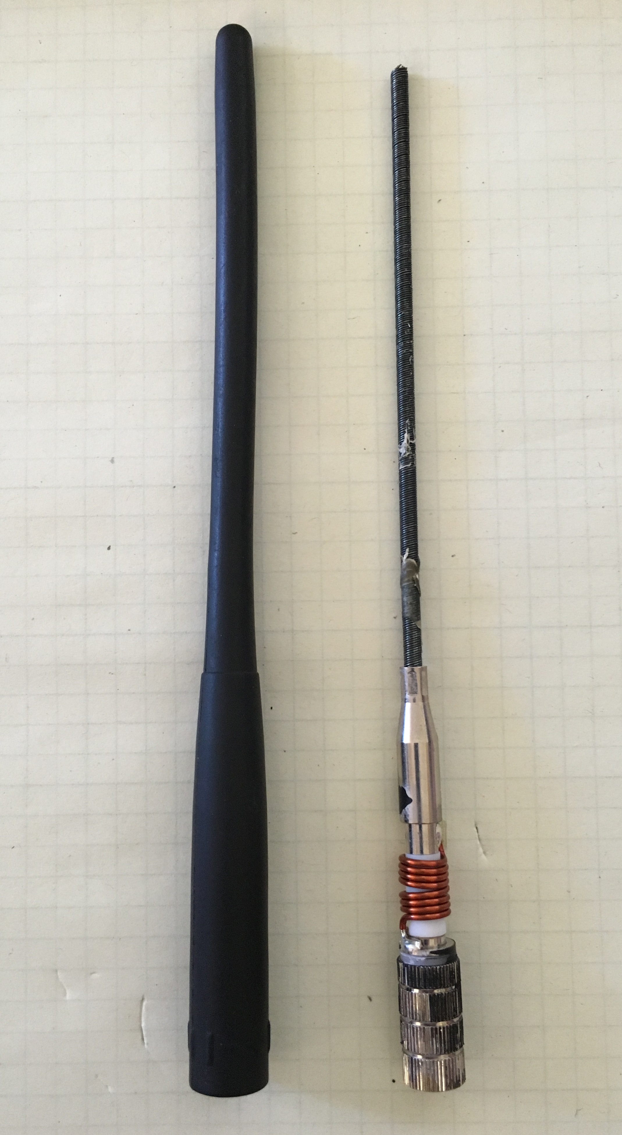
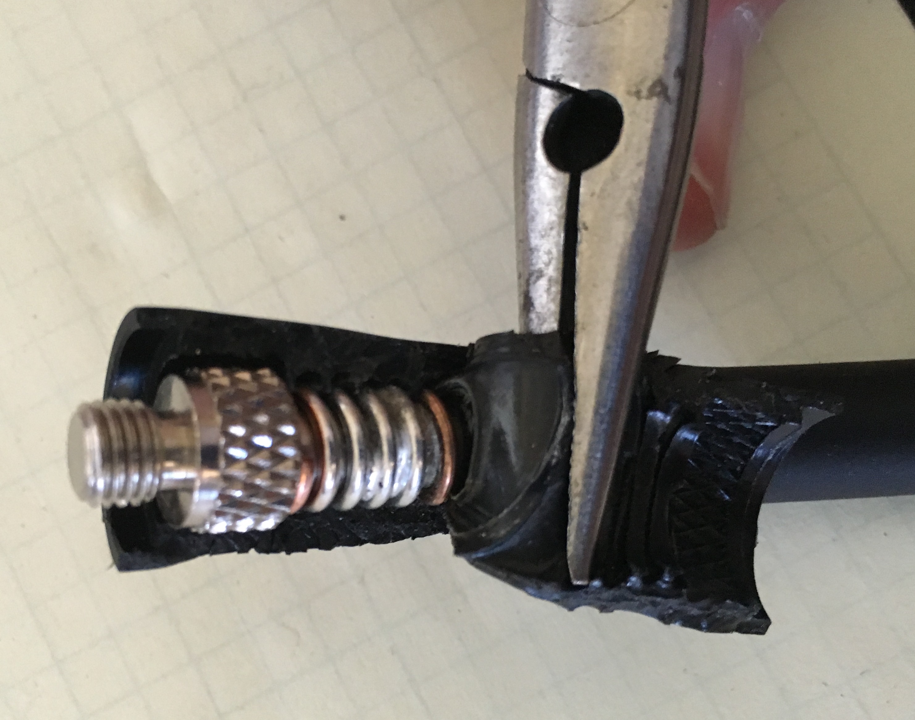
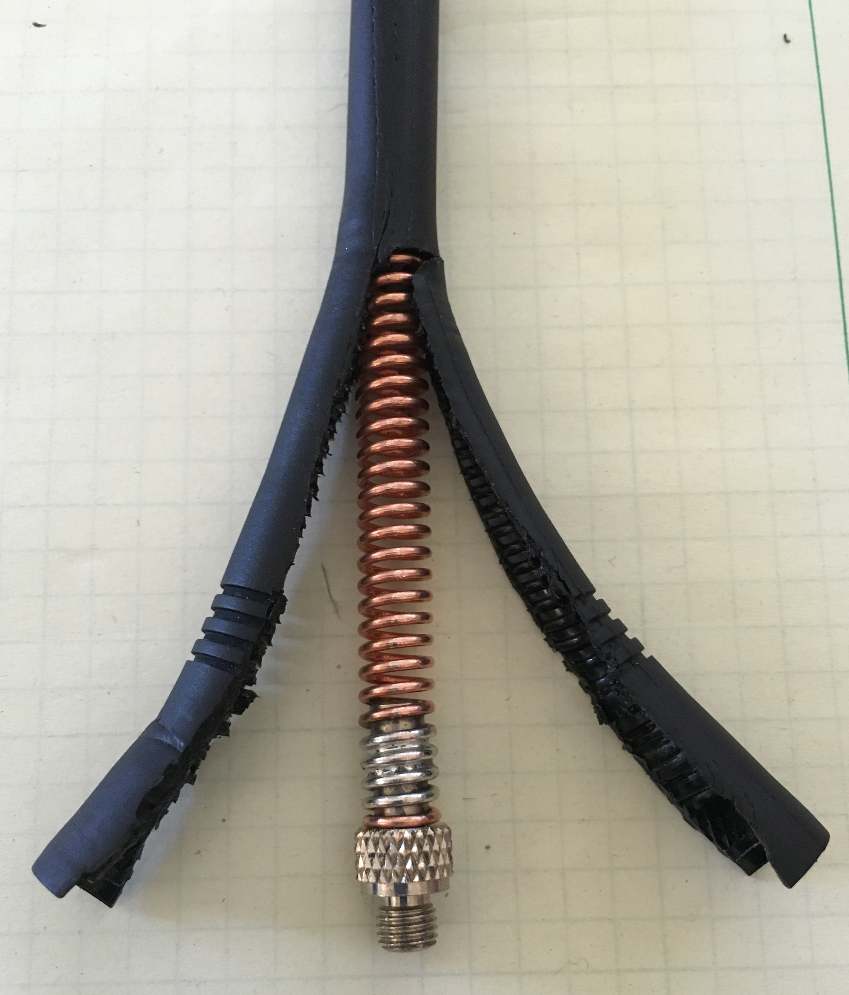
The Yaesu antenna was easy to disassemble. In fact, I chose this antenna because I noticed that the outside jacket had come loose and was starting to slide off the antenna. A steady pull on the cover exposed the antenna elements without any further antenna abuse. (I plan to reinstall the cover with a few dabs of glue and expect that it will continue to work fine.)
The construction of this antenna is quite different from the Baofeng. The main element is a very tightly-wound spring…so tight that I expect that it acts like a solid wire electrically. In other words, it doesn’t have the spiral configuration that makes the antenna act longer electrically. At the bottom of the antenna, there is a coil inserted in series with the radiating element (connects radiating element with the center pin of the SMA connector).
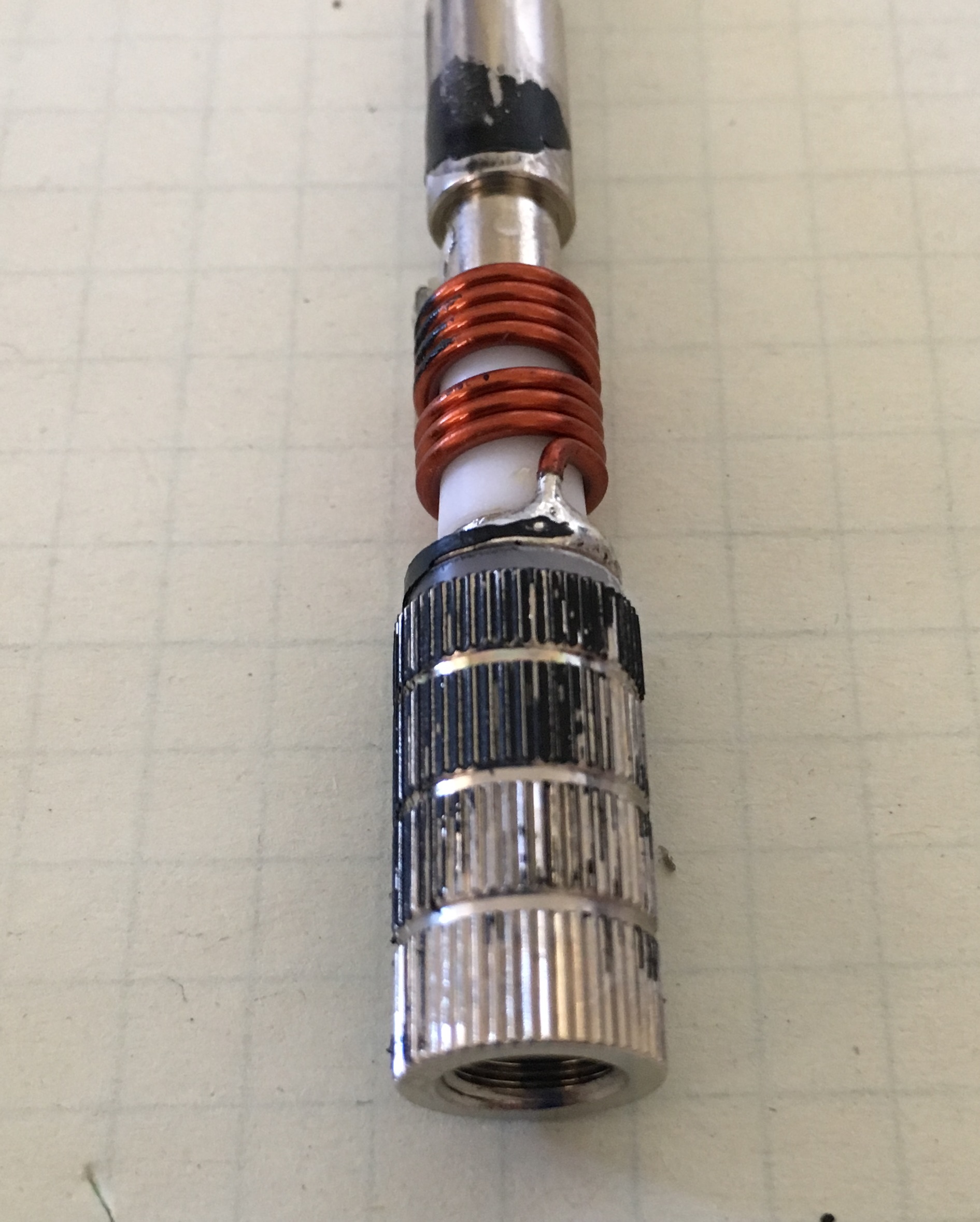
The photo to the right shows a closeup view of the male SMA connector and the coil.
Laird VHF Antenna
Next, I wondered if antennas for commercial radios had different design or construction techniques. Laird makes high-quality antennas for the mobile radio and other commercial markets, so I purchased one of their VHF rubber duck antennas to dissect. This model is intended for use with Motorola radios requiring a threaded antenna stud.
This antenna was a challenge to cut open. I used a sharp knife and diagonal pliers to cut the rubberized jacket and peeled it back using a needle-nose pliers. The rubberized coating was embedded into the spiral antenna element, so it did not come apart easily. It took over an hour fighting with the antenna and I gave up before getting the entire spiral element exposed.
The Laird antenna is clearly the sturdiest of the three antennas. The spiral element is much thicker than the Baofeng and the rubberized coating is tougher and molded tightly into the spiral element.
The Baofeng and Laird antennas use the same design concept…just take a spiral antenna element and apply a protective cover. However, the Laird construction was far superior, but not a surprise given that Baofeng is a low-cost provider in the ham radio (consumer) market.
My disappointment is with the Yaesu antenna. The antenna came apart after one year of not very heavy use. I expect I can put it back together with some adhesive, improving on the design in the process.
Anyway, I found this interesting and wanted to share it with you. What’s in your rubber duck?
73, Bob KØNR
The post What’s In Your Rubber Duck? appeared first on The KØNR Radio Site.


