Archive for the ‘antennas’ Category
 Remembering The ‘Woodpecker’
Those of you that have been hams for a long time will no doubt recall the Russian 'Woodpecker'. The 'Woodpecker' was a strong, fast repeating signal / racket that often wiped out amateur communications on 20m here in North America ... maybe other parts of the world as well.
Amateurs with yagis eventually determined that the signals (yes there was more than one it seemed) were coming from the USSR. The QRM was persistent and in spite of formal complaints being lodged via diplomatic channels, continued for many years ... from 1978- 1989. Some of the new transceivers built during the time actually had a 'WOODPECKER' position on the noise blanker switch, hopefully offering some relief to the problem.
For you younger folks, here's what Duga usually sounded like:
Several web searches brought up numerous descriptions of the Duga (Russian for 'arc' or 'bow') project, some with conflicting information. From what I can sort out, there were three Duga sites ... one near Chernobyl, another near Chernihiv and a third, much later, in Siberia. The first two (Duga and Duga-1) were in the Soviet Ukrainian SSR (now Ukraine) while the third was located near Komsolmosk-on-Amur in the Russian far east. One source indicates that the second Chernobyl site is often misidentified as the Duga-3 array and should be referred to as Duga-1, with Duga-2 being the Siberian location.
Initial speculation suggested this intrusive signal was some form of 'jammer' ... very common during the Cold War. It wasn't long before the true nature of Duga was thought more likely to be an 'over-the-horizon' (OTH) long-range radar system for detecting the launch of North American missiles aimed at the USSR. The three radar sites gave the Soviets good over-the-pole coverage as well as to the east, where it could also be utilized for tracking domestic rocket launches.
 |
| courtesy: http://www.globalsecurity.org/wmd/world/russia/steel-yard.htm |
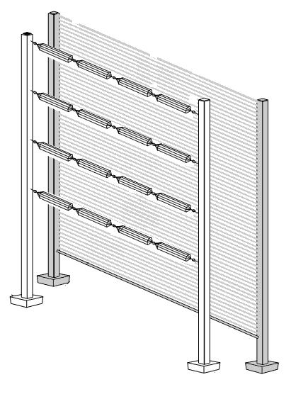
The antennas themselves appear to be phased dipole curtain arrays, commonly used in various configurations by shortwave HF broadcasters.
 |
| courtesy: http://www.antenna.be/hr.html |
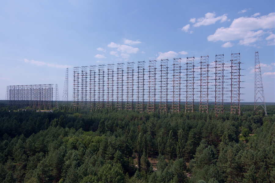
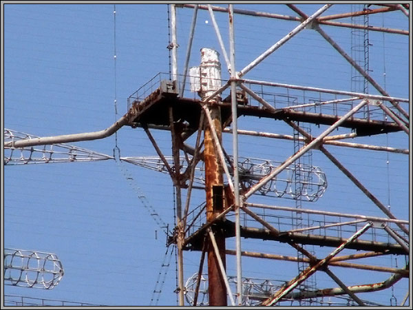
Each site was paired with a receiving array ... remember, this was a radar system, with two of the three systems having the receiving array located tens of kilometers from the transmitter. The Chernobyl Duga is said to have had the receiving antenna located on site. Sources discussing physical size indicate the dimensions for the receiving array to be larger than those of the transmitting antenna. It seems possible then, that the pictures and videos commonly found are those of the receiving array and not of the transmitting antenna. It might make sense to have more gain on 'receive' than on 'transmit' as echoes from small targets many thousands of miles away would not be easy to detect. No matter what the actual case, I can only imagine the fun of hooking up an HF transceiver to one of these arrays during a DX contest on 20m CW!
The Chernobyl site shows two arrays, side-by-side ... possibly the larger being that used for receiving and the smaller one for transmitting. This antenna has been noted as a 30/10/2 array ... 2 bays, 30 dipoles wide and 10 high, 600 elements in all!
Further research tends to indicate that each dipole is what is called a 'Nadanenko' dipole. The main feature of this style was its cage-styled construction, giving the element a large diameter resulting in a broad bandwidth.
 |
| courtesy: https://shema.info/en/antenna/ |
 |
| courtesy: englishrussia.com |
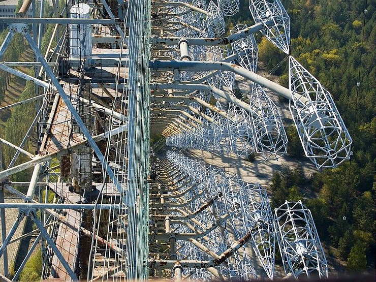
First, you see that there are two sets of arrays 15 driven elements wide by 10 driven elements high for a total of 600 elements! They are intermeshed and offset from each other by 1/2 wavelength both vertically and horizontally. There is a horizontal wire screen reflector behind the driven elements.
Some of the other things I noticed are ...
... you can see the open-wire feeds and reflector screen. Each set of collinear elements is fed individually with open wire line. There is a support line between each two bays of driven elements.
... that the reflector screen is supported on the sides by the stand-alone free-standing towers at each side of the array. (I had been wondering why they would have those towers next to the array like that. Now I know.)
... that the element supports are steel pipe instead of fiberglass (or something similar). Apparently, the shape of the radiators allows for the pipe supports to enter the element cages at the element low-impedance point which made the supports invisible to the antenna and also allowed for the supports to not radiate themselves.
 |
| courtesy: http://anzee.livejournal.com/65530.html |
The Duga system was operative between 7 and 19MHz, with 40kHz wide pulses, usually lasting for about seven minutes. The most common pulse rate was at ~10Hz but this sometimes varied. Power levels used often mention 10 megawatts but it's not clear if this was RF output, peak pulse power or ERP.
It's somewhat gratifying after all these years, to actually see close-up, where the Woodpecker signal started its journey around the world and to appreciate the superb engineering that went into these impressive structures ... but sad to see the last one in such a rusted state of decay and abandonment. It would be nice to hear it just one more time ... but please, only for a couple of minutes.
Antenna tuning by stealth
One of the most important documents for anyone who wants to know what makes a magnetic loop tick is Leigh Turner VK5KLT’s “An Overview of the Underestimated Magnetic Loop HF Antenna” which can be found on his club website.
Midway through building my version of Loftur Jónasson – TF3LJ / VE2LJX‘s Automatic Loop Controller, I came across Leigh Turner’s impassioned plea to consider this noise bridge antenna tuning design mentioned on page 32 of the “Overview”. As a concluding note VK5KLT states that he considers “The perceived need for a slick and salubrious auto-controller for properly tuning an MLA is oftentimes overrated and exaggerated, IMHO”.
He argued that elaborate microcontroller aided automatic loop tuning circuits are unnecessary and people should consider using this more covert and considerate approach. I think the bridge could be an excellent idea and a simpler way of staying in tune as you change frequency for all sorts of antennas. For a magnetic loop, it still requires a way to remotely adjust the tuning capacitor.
“The circuit goes inline between the rig and the antenna and sends a gated broadband noise signal to the antenna using a directional coupler and a noise bridge. You just listen on the desired operating frequency and watch your RX S-meter for a sharp dip whilst adjusting the loop tuning capacitor.
You simply remotely tune the loop with the aid of the receiver S-meter while you are on the wanted frequency without keying up and TX power output. This makes tuning a breeze without having to move off frequency and have the TX put out any RF power.”
VK5KLT mentioned the MFJ-212 Matchmaker that uses this same approach (and which is still on the MFJ catalog at US$99.95) and also referenced ZL3KB’s April 2001 RadCom article (pp17-21) as an easy and more economical way to replicate the same functionality.
“The distinguishing merit of the novel gated coupler/noise bridge loop tuning method is it’s completely passive and covert in operation; you don’t transmit any TX power whatsoever to attain an optimal loop tune setting. The technique makes for fast, QRM free, safe and easy QSY shifts and netting a frequency.” Leigh Turner adds that it’s even simpler if you use a pan adaptor or a modern SDR receiver as you can see the sharp null on the screen of the band scope display.
Kelvin Barnsdale ZL3KB’s RadCom article describes building and using the wide band noise bridge as a silent antenna tuning indicator. These four pages include circuit, PCB design and layout and full details of BOM and balun/transformer construction.
On 14 May 2001 ZL3KB published a 4-page follow-up pdf document “Instructions for Antenna tuning Noise Bridge” with info supplementary to the RadCom article about construction and operation. This article has an updated circuit and parts layout and refers to an issue B of the PCB. The new board includes places for the LED and dropping resistor R14, and pads for the two 100Ω load resistors and the two diodes D2 & D3.

This is the updated circuit with some updated values.

This indicates parts placement with the updated PCB.
Here is the foil side of the updated PCB

I contacted Kelvin Barnsdale and was lucky enough to obtain the PCB above.
Buddipole vertical for 80m
I spent the pleasant sunny part of the final day of autumn testing a vertical antenna for 80 metres using Buddipole parts for home.
The back garden space here is barely 4 metres by 4 metres and for the moment the chimney is out of reach. While I have dreams of a magnetic loop for 80m, the vertical is more in reach now.

I installed a counterpoise wire a few feet shy of 66 feet length hidden on a timber fence that runs down the side of the property. The idea is to connect a short fly lead to connect the hidden counterpoise when the antenna is deployed and then disconnect when it’s all packed away. Buddipole components don’t lend themselves to permanent installations. The counterpoise doesn’t follow the recommended dog leg arrangement and is higher off the ground than the 2 feet suggested.
The purpose yesterday was to establish how speedily the antenna could be assembled and adjusted for a frequency of interest such as a net.
Here’s a list of the items used along with the counterpoise:
9′ telescopic whip
2 x 22 inch antenna arms
low band coil + clip
VersaTee
Buddipole short mast
Buddipole tripod
Balun
I was surprised how easily it all went together. The adjustment wasn’t as fiddly as I expected such a short antenna for this band would be, and it appeared to give a usable bandwidth.

Assembly was straightforward. Set up the tripod and mast with only bottom two sections telescoped out. Attach the Versatee horizontally to the top of the mast. Connect the Low Band coil. Leave the red fly lead loose for the moment. Attach two 22 inch antenna arms to a long whip antenna fully extended. Then carefully attach that assembly to the top of the Versatee. I also connected a 1:1 balun between the Versatee and the iP30 SWR Analyser.
The next step is to simply drag the fly lead across the coil turns to identify the best spot to tap the coil. Background noise level rises as you get in the zone. I used the iP30 SWR analyser to narrow it down to a spot 16 turns up from the base of the coil.
This means I was shorting out the bottom 16 turns of the coil. The adjustment is too coarse on a turn by turn basis. You appreciate the value of being able to tap at 1/8 of a turn increments. (The coil is on an octagonal former.)
It took me a few measurements to realise that as I progressed left (from my point of view) I was decreasing the amount shorted out and hence increasing the loading inductance and so lowering the resonant frequency. It’s actually more confusing reading that sentence than understanding it in practice!
My target frequency was 3535kHz and this is a chart of the SWR readings I had when the coil tap was set at what I calculate to be 15 3/4 turns up from the base of the coil.
| frequency | SWR | frequency | SWR |
|---|---|---|---|
| 3505 | 1.8:1 | 3550 | 1.1 |
| 3510 | 1.6 | 3555 | 1.1 |
| 3515 | 1.4 | 3560 | 1.1 |
| 3520 | 1.3 | 3565 | 1.2 |
| 3525 | 1.2 | 3570 | 1.3 |
| 3530 | 1.1 | 3575 | 1.4 |
| 3535 | 1.0 | 3580 | 1.5 |
| 3540 | 1.0 | 3585 | 1.6 |
| 3545 | 1.1 | 3590 | 1.8 |

The 1.0:1 bandwidth was 10 kHz while at 1.5:1 it was in excess of 65 kHz.
From readings at the other possible coil tap points my guess is that at this frequency range each face of the coil moves the resonant frequency by about 4 kHz. One thing to be aware of with the Buddipole hardware is not to accidentally short out adjacent turns of the coil with the coil clip. It’s hard to do but I managed and it will throw your readings.
Next step of course is to make some contacts or at least activate the antenna on WSPR or JT65 to get an idea of whether the signal gets over the fence.
From checking the chart on page 146 of the ‘Buddipole in the Field’ book by B. Scott Andersen, NE1RD, I estimate that my shorting tap at about 16 turns from the base means I’m using about 39-40 uH of loading to achieve resonance at 80m. So that’s a starting point if I wanted to build a more permanent and cheaper vertical installation.
EFHW: progress on 20 meters
I’ve made some progress on the EFHW antenna since my last post here on AmateurRadio.com. I wound a new transformer, but now on a thinner plastic tube. Initially it had a 10:1 ratio, but after some initial tests at home I removed some turns and now it is 8:1.

Today, out on the parking lot, I managed to get a good match on 20 meters with 10 meter wire and a 1 meter counterpoise. A short video to prove this.
It was quiet on 20 meters in mid-afternoon. Only HS0ZJF came in with a reasonably strong signal and it was easy to work him. He gave me a 549 for my 5 Watt QRP signal and I was more than happy with that. And as fate would have it HS0ZJF is originally from Belgium, so we exchanged some Dutch greetings as well.
On 40 meters I wasn’t so successful. This time I tried various lengths of wire, ranging from 19 to 23 meters, but the lowest I could get my SWR was 2.4:1. Funny thing was that the KX3 wouldn’t put out the 3 Watts used when tuning at an SWR of 2.4:1, but it had no problem putting out more at a higher SWR of 3:1 or more. Now the SWR is measured behind 3 meters of coax at the KX3, which is not ideal, so the next step is to make a LED-based resistive SWR bridge to be put right behind the antenna and before the coax. 
I could make it tonight, but unfortunately I only had two 51 ohm 5W resistors in my junk box. Back to the shops it is.
The Joys Of ERP
Although this doesn't sound like much, mustering this amount of effective power can be quite a task on either band, especially on 2200m. This is due to the very poor efficiencies encountered when using antennas that are so small in size compared with what would be considered 'normal'. For example, a typical 1/4 wave vertical used on 40m is about 33' high and with a good radial system can achieve efficiencies in the 80% range, while the equivalent antenna for 2200m would be 550m or about 1800' high ... a little large for most suburban backyards!
The equivalent of a normal 2m 'rubber-ducky' antenna when built for 2200m would be over 600' tall, while one designed for 630m would be around 170' high! A 2" stub used on your 2m hand-held would be the same as a 56' vertical on 630m. Consequently, most LF / MF backyard antennas will realize efficiencies of less than 1% and likely, quite a bit less.
In order to reach the maximum radiated power levels allowed usually requires several hundreds of watts, especially on 2200m, where near kilowatt levels are needed. These small radiated power levels might seem discouraging but they don't account for radio's great equalizer ... propagation. More than anything else, RF loves to radiate, and at times, what can be achieved on these bands with such low effective radiated powers is stunning
It would seem that Industry Canada did us no favors when they stipulated LF / MF power levels to be measured in EIRP and not the, much easier to calculate, DC power input level ... or perhaps they did. I think that, unlike on HF, imposing EIRP rather than DC input power limits puts everyone on an even playing field. Amateurs with lots of real estate and room for a larger, more efficient LF antenna, will be required to run much less power to reach the allowable EIRP and 'stay legal', compared to someone with a small backyard in the suburbs ... the latter can legally generate the higher level of DC input power required to reach the EIRP limits since their smaller antenna is operating at less efficiency. However, determining EIRP is not as cut and dried as measuring input power.
With some fairly sophisticated (ie. expensive) field strength measuring equipment, not typically found in amateur radio operations, ERP / EIRP can be readily determined. This means that for most amateurs, alternate methods must be used.
Neil, WØYSE in northern Oregon, who runs an experimental 630m station under the call of WG2XSV, has produced an excellent treatise on calculating your station's EIRP level, providing a step-by-step procedure to follow.
In order to determine your ERP / EIRP, you must first determine your antenna's radiation resistance. Two methods of calculating the antenna's radiation resistance for both verticals and top-loaded verticals (inverted L's or T's) are demonstrated, using the physical size of the antenna in relation to the frequency of operation. Once this value is known, the antenna current is measured while transmitting. These two values allow the Total Radiated Power (TRP) to be calculated. The TRP is then multiplied by 3 to yield the EIRP or by 1.82 for ERP. Roughly speaking, 5W EIRP is the equivalent of 3W ERP. Thanks to Neil for this helpful resource.
An alternate method of roughly determining ERP / EIRP values is an interesting new online 'antenna simulator' at the 472kHz.org site. Using known physical sizes along with your ground quality description, the calculator will indicate what total power output is required to produce various levels of ERP and EIRP as well as expected antenna currents, at 472kHz. It's a good starting point if you are either planning a new antenna system or perhaps, repurposing an HF antenna such as an 80m inverted-L or an HF center-fed dipole for use on 630m.
There are also a number of online calculators, such as found here, that will indicate your ERP / EIRP value when you plug in your antenna's 'gain' figure along with your TPO value. Some of the better antenna modelling programs can produce estimates of your antenna 'gain' at 630m and from there it is a simple matter of calculating what power is needed to reach the legal level.
I'm sure there will be a lot more information and discussion about this topic once the LF and MF bands are released in the U.S.A. but in the meantime, calculating your ERP / EIRP levels is not as hard as it might initially seem ... and is likely accurate enough for most agencies overseeing amateur radio activities.
It was an NPOTA weekend …..
I worked about 5 or 6 new entities between Friday night and Saturday, so I am getting really close to my personal goal of working 100. The bands have been good the past couple of days, after totally stinking during the middle of the week, so that was a good thing.
I have lived relatively near Morristown National Historical Park my entire life. I think I've been there once before NPOTA. Yesterday, I decided to take Marianne and our dog, Harold up there for the afternoon, as dogs are welcome there. It was a beautiful Spring day, Marianne had an extremely rare Saturday off; and I wanted to do something with her. It seemed like a good opportunity to enjoy the gorgeous weather, walk the dog and get some good exercise in for ourselves. It's because of NPOTA that I discovered that dogs are welcome there. If I didn't see that while I was up there, activating the park, I wouldn't have known otherwise.
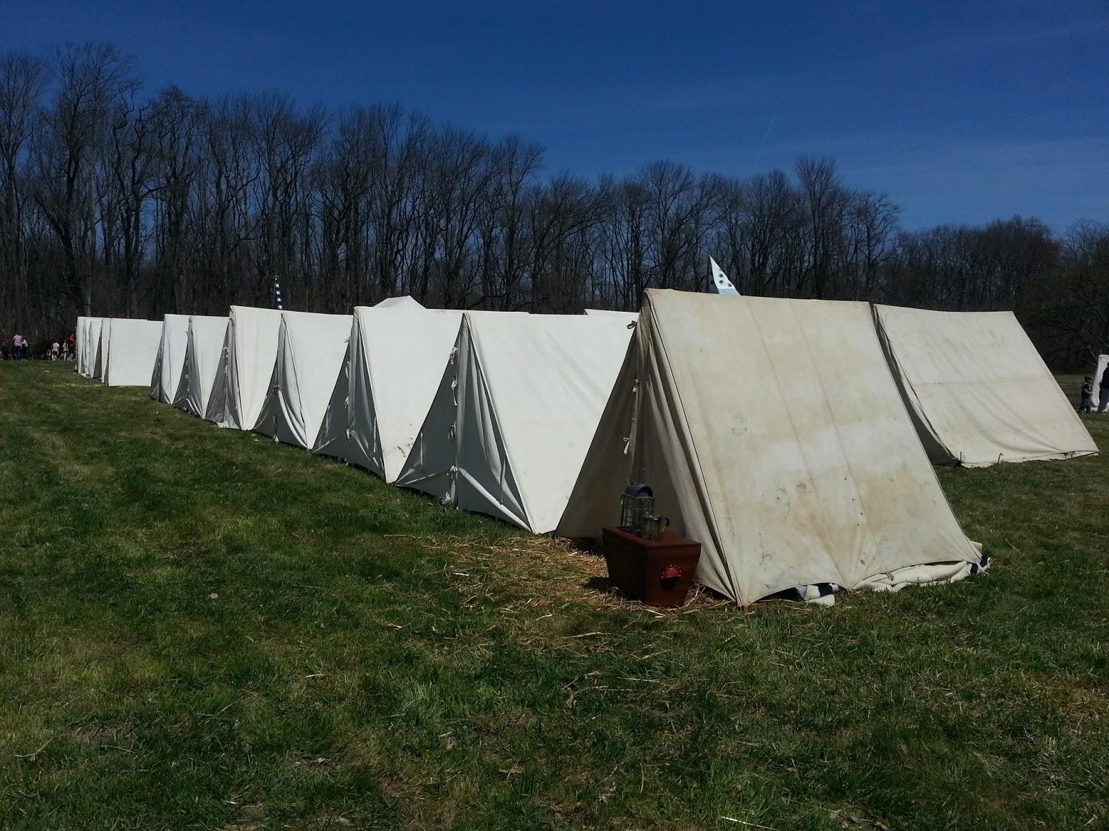
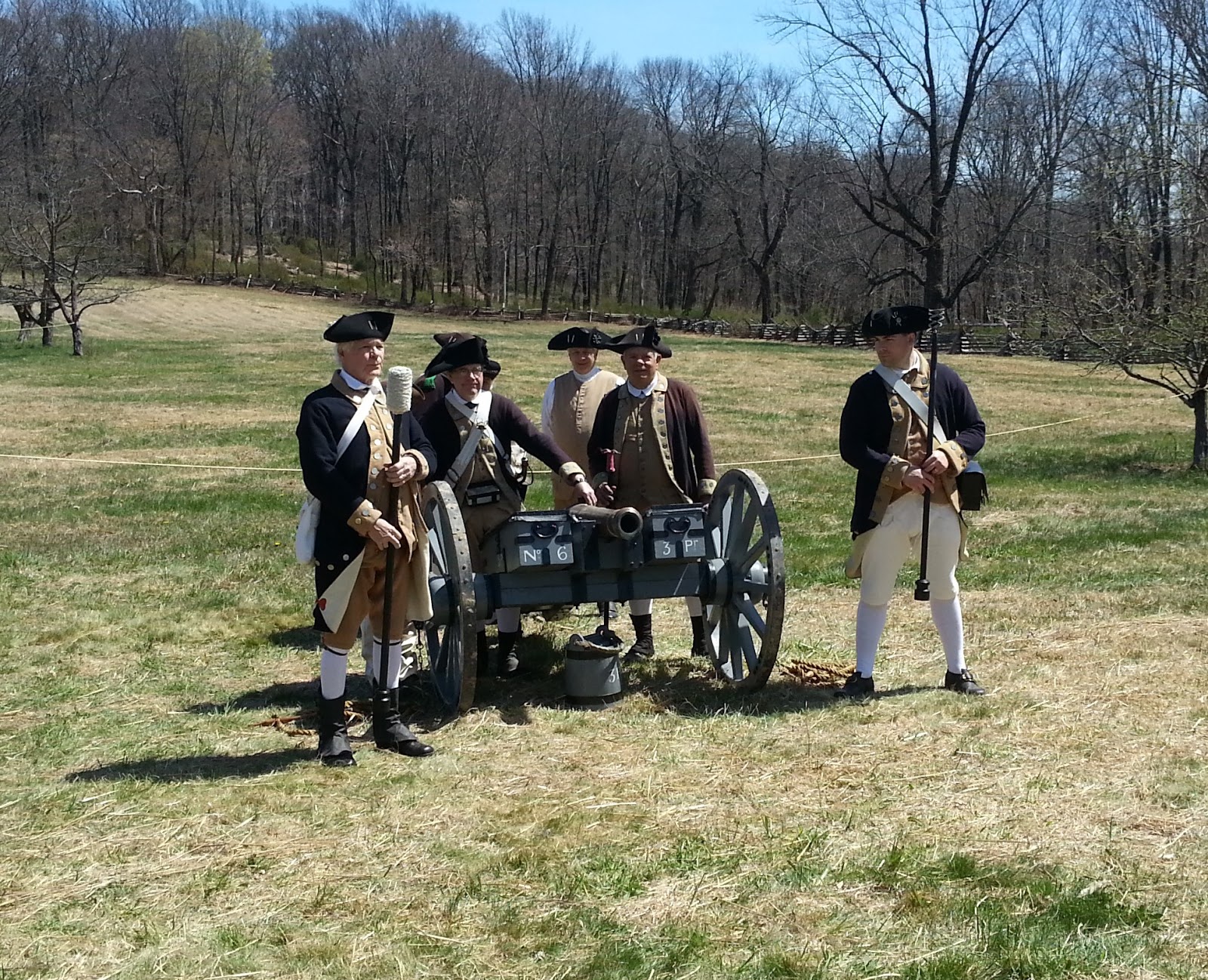
Much to our surprise, when we got there, we found out that a Revolutionary War re-enactment was taking place:
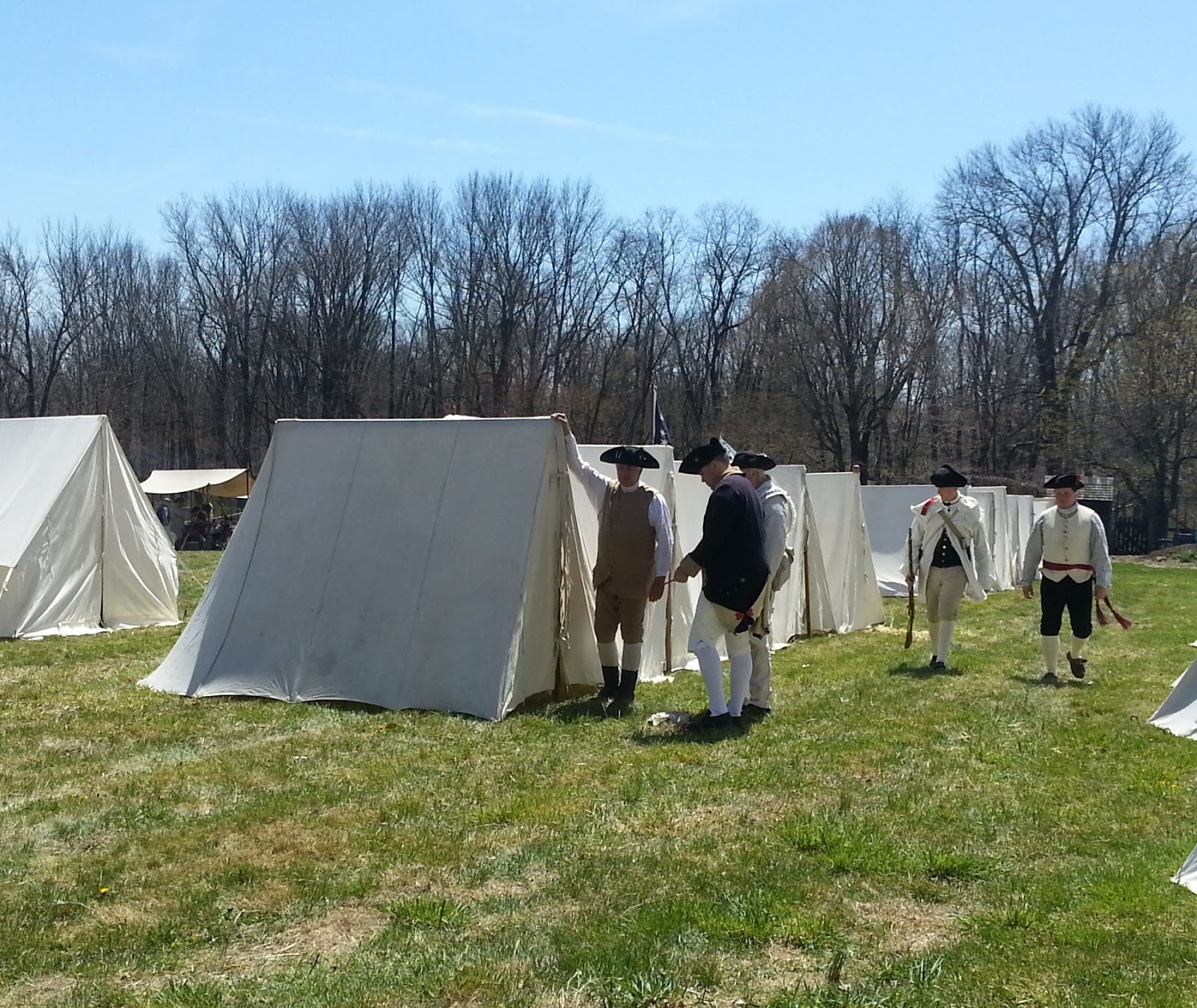

The highlight of the day was when one of the re-enactors came up to me and tapped me on the shoulder. He pointed to the American flag that is embroidered on the left sleeve of my jacket and he said to me, "Kind sir, a question, please. It appears that you have a United States flag on your coat; and yet there are so many stars? Certainly more than 13!"
I answered, "It's a long and sometimes bloody story, and I don't think we have time to go through it all, but I would like to thank you and your fellow soldiers for giving birth to the finest Nation on Earth."
He chuckled, and I chuckled at our impromptu time travelling scenario. In the end, it was great NPOTA day, even though this one didn't involve Amateur Radio. So hats off to the ARRL for reminding me about some of the really cool places that there are to visit around my QTH.
In the evening, I decided that I would go out early Sunday morning to activate Sandy Hook, which is part of the Gateway National Recreational Area - RC08.
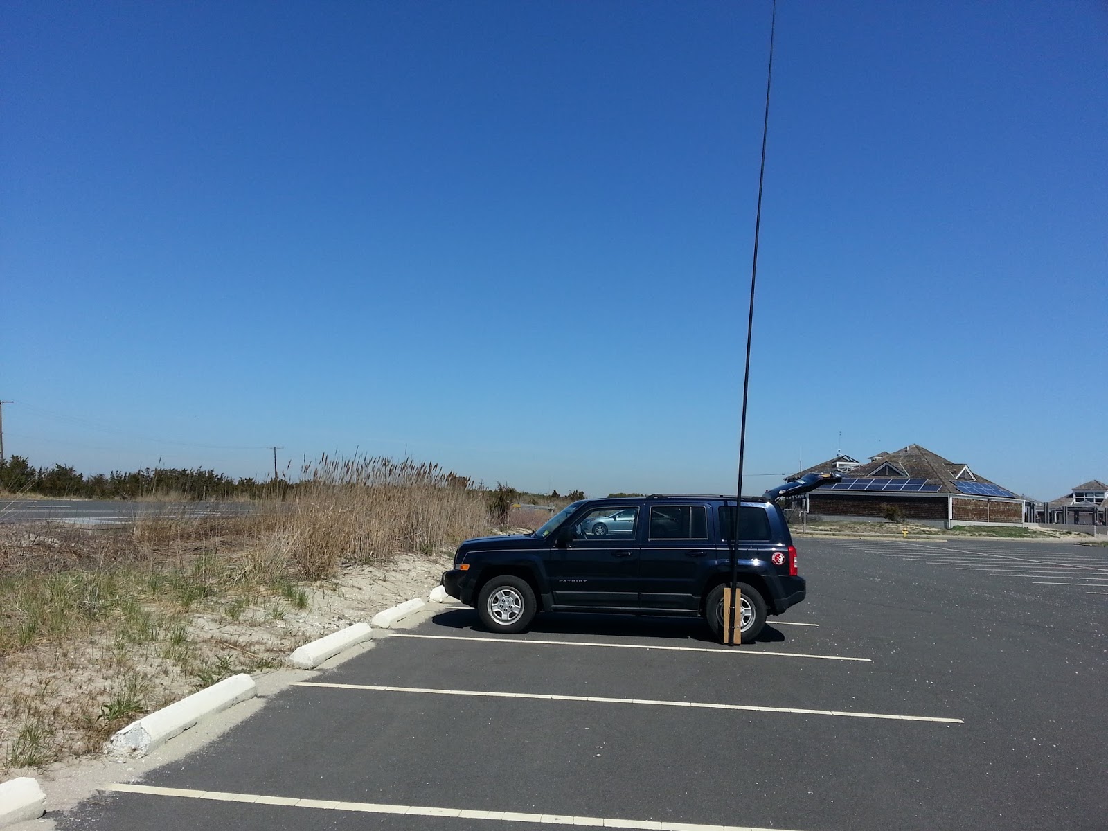
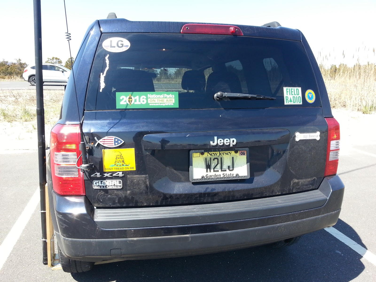

I used the Jackite pole and my homebrew mast holder and the PAR END FEDZ 40/20/10. In a little over an hour, I made over 40 contacts on 40 and 20 Meters. Bext DX was Alberta, Saskatchewan and California. Not bad for 5 Watts, and if at all possible, the PAR will be my preferred antenna for future activations.
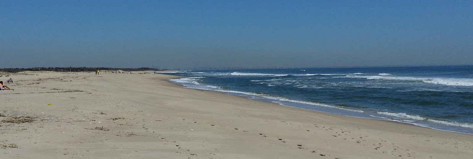
I would have stayed longer, but I had somewhere to go with my daughter Cara, so I made due with the time I had. It was a bit brisk while I was there, but it was sunny and clear. If you click on the bottom photo, you just might be able to make out the New York City skyline in the distance, on the horizon.
Sandy Hook was my third activation, and I hope to do at least two more in New Jersey - the Pinelands and the Appalachain Trail in the Northwest part of the state. When we go up to Lake George this Summer, I also hope to spend one day at Saratoga and activate HP42 while I'm in the neighborhood.
72 de Larry W2LJ
QRP - When you care to send the very least!
It was an NPOTA weekend …..
I worked about 5 or 6 new entities between Friday night and Saturday, so I am getting really close to my personal goal of working 100. The bands have been good the past couple of days, after totally stinking during the middle of the week, so that was a good thing.
I have lived relatively near Morristown National Historical Park my entire life. I think I've been there once before NPOTA. Yesterday, I decided to take Marianne and our dog, Harold up there for the afternoon, as dogs are welcome there. It was a beautiful Spring day, Marianne had an extremely rare Saturday off; and I wanted to do something with her. It seemed like a good opportunity to enjoy the gorgeous weather, walk the dog and get some good exercise in for ourselves. It's because of NPOTA that I discovered that dogs are welcome there. If I didn't see that while I was up there, activating the park, I wouldn't have known otherwise.
Much to our surprise, when we got there, we found out that a Revolutionary War re-enactment was taking place:
The highlight of the day was when one of the re-enactors came up to me and tapped me on the shoulder. He pointed to the American flag that is embroidered on the left sleeve of my jacket and he said to me, "Kind sir, a question, please. It appears that you have a United States flag on your coat; and yet there are so many stars? Certainly more than 13!"
I answered, "It's a long and sometimes bloody story, and I don't think we have time to go through it all, but I would like to thank you and your fellow soldiers for giving birth to the finest Nation on Earth."
He chuckled, and I chuckled at our impromptu time travelling scenario. In the end, it was great NPOTA day, even though this one didn't involve Amateur Radio. So hats off to the ARRL for reminding me about some of the really cool places that there are to visit around my QTH.
In the evening, I decided that I would go out early Sunday morning to activate Sandy Hook, which is part of the Gateway National Recreational Area - RC08.
I used the Jackite pole and my homebrew mast holder and the PAR END FEDZ 40/20/10. In a little over an hour, I made over 40 contacts on 40 and 20 Meters. Bext DX was Alberta, Saskatchewan and California. Not bad for 5 Watts, and if at all possible, the PAR will be my preferred antenna for future activations.
I would have stayed longer, but I had somewhere to go with my daughter Cara, so I made due with the time I had. It was a bit brisk while I was there, but it was sunny and clear. If you click on the bottom photo, you just might be able to make out the New York City skyline in the distance, on the horizon.
Sandy Hook was my third activation, and I hope to do at least two more in New Jersey - the Pinelands and the Appalachain Trail in the Northwest part of the state. When we go up to Lake George this Summer, I also hope to spend one day at Saratoga and activate HP42 while I'm in the neighborhood.
72 de Larry W2LJ
QRP - When you care to send the very least!


