Author Archive
 Autumn Antenna Adventures Again….
…with Arduino.
I’m not well versed in mechanics. Motors, gears, bearings….not my forte. I know how to work with wood, but not with metal. However, as a ham you should posses some mechanical skills, right? How else will you get these antennas built, up in the air on a tower, with a rotor to move them?
So, for tuning my loop I decided to learn something new and use a stepper motor to turn the variable capacitor. Amazing things, these stepper motors! There was a lot to read about them, like the types (unipolar or bipolar), stepcount, gearing and wiring.
In the Arduino beginners kit I bought for my son there was a small stepper motor, the 28BYJ-48. It’s a 5 Volt motor, so a perfect fit for an Arduino.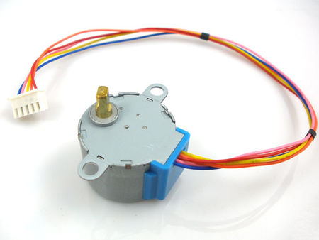
I “salvaged” it from my son’s room and hooked it up. Here is a web page about it with all the specs. There is also a code sample on that page and it shows that controlling a stepper motor is not difficult at all. But the code uses a lot of switch statements and that gets unwieldy very quickly.
In such cases a library will help out. A library is just that: a place to look up code to use in your own code. This is usually done by referencing to it and as long as your library is included in your IDE you are good to go. To understand more about how libraries work and how to write one yourself I found this tutorial on the web. I followed it and indeed ended up with my own library to control the stepper motor.
But don’t worry, you don’t have to write every library you need. For almost any input or output device there is a library available and the most basic ones are included in the Arduino IDE. If not, a quick search on the web will yield one you can use, but then you will have to install it yourself (not difficult if you use the Arduino IDE).
With the library installed code looks like this….

The first of the three block of the code has two lines:
#include StepperMotor.h
 StepperMotor myMotor(8,9,10,11);
The first line doesn’t need explaning, except that libraries usually end in “.h”. In this case my library is simply called StepperMotor.h.
Now I might have more than one stepper motor hooked up to my Arduino, so I have to make it clear which motor I’m using. Here I use only one motor, so my code reads:
StepperMotor myMotor(8,9,10,11);
In plain English this says that in my code any mention of “myMotor” will reference to the StepperMotor library and it will use the motor connected to pin 8 through 11. If I would have used two motors my code it would have been…
StepperMotor myMotorOne(8,9,10,11);
 StepperMotor myMotorTwo(4,5,6,7);
In the setup I add this:
myMotor.setStepDuration(1);
In the library there is a function to set the duration of one step. By simply referencing to is and adding a value between the brackets it has been set. I don’t have to worry about the code that sets the step duration, because the library takes care of it all. Ease and simplicity at its finest.
Now I can control my stepper motor in the loop block:
 myMotor.step(4800);
 delay(2000);
 myMotor.step(-4800);
 delay(2000);
myMotor.step() looks up the library function to move the motor and then moves it 4800 steps. After a delay of 2 seconds it moves the motor back 4800 steps. Another 2 second delay and the process repeats itself.
Fine and dandy, but this code might only be useful for moving an advertisement sign, not much else. In my case I needed to control a variable capacitor, so mounted everything on a piece of plexi glass, added a few push buttons and the result looks like this…..
In the end there was a lot more that needed to be added to get it working perfectly. Preventing button bounce was one thing, limit switches were another. Physical limit switches were not an option, so I devised a software solution. To go from maximum capacity (500pF) to minimum capacity (9pF) the stepper motor needs 11000 steps. In my code I therefore added a counter and as long as this counter stays between 100 and 10900 the stepper will work. Now I don’t have to worry about stressing the stepper motor when it reaches either end of the capacitor. By putting the counter’s value in the Arduino’s Eprom I can switch the loop off without losing its settings.
With this part of the project done it’s time to put everything together and box it up.
More Autumn Antenna Adventures….
…with Arduino.
Last time I showed you how easy it is to hook up a relay to an Arduino MCU. Without some human control, however, it is a pretty useless setup. It needs switches and the switches most used in the Arduino world are momentary push buttons. They are versatile as just by altering some code you can change a momentary switch into a toggle switch or a rotary switch. Nifty!  Hooking them up is not quite straightforward, though, because they need either a pull-up resistor or a pull-down resistor. The voltages on Arduinos I/O (input/output) pins alter between two states: 0 and +5 Volt. When an I/O pin is connected to either ground (pulled down, LOW) or +5V (pulled up, HIGH) by shorting a switch, this state is easily read by the Arduino. But when the switch is not shorted the I/O pin “floats” and its state is not certain due to electrical noise; it might be anywhere between 0 and +5V. It’s difficult to tell what the Arduino will read then: either HIGH or LOW, but this is anybody’s guess. To prevent this from happening both ground and +5V are connected to the switch to make sure the I/O pin will see two clear states. To prevent damage due to high currents a 10k resistor is added.
With that out of the way and everything hooked up the fun stuff can begin. 
Just like last time we first define what I/O pins we use. Apart from the relayPin we now also have a buttonPin, namely A0. In the setup we now declare that buttonPin is used for INPUT, as we already defined that the relayPin is used as an OUTPUT pin.
The part which the Arduino loops through (over and over) looks a bit more complex now. It features an “if” statement:
if (digitalRead(buttonPin) == HIGH) {
 digitalWrite(relayPin, HIGH);
 }
This is not so difficult as it looks. In plain English it reads: “if you read out the buttonPin and it is equal to HIGH, execute the commands that are sandwiched in between { and }“. And the single command is the same as last time: write to the relayPin and make it active, or HIGH.
But what in other cases? That is the next part, which begins with “else“.
else {
 digitalWrite(relayPin, LOW);
 }
In all other cases make the relayPin LOW or inactive.
The result of all this you can see in the following short video.
Better, but still not useful enough. Once we release the button our relay also deactivates. A toggle switch is what is needed in this case, so let’s change the code and make it into one.
And this is where I find joy in working with Arduinos. With just three lines of code I can change the behaviour of a push button. There are loads of examples on the web that use lots more code to achieve the same result, but by being clever it can be done far more efficiently. Discovering this gives me the same kick as working a new DXCC entity, or building a circuit which works the first time. Although it almost wrecks my brain sometimes, the reward makes it all worth it.
Let’s take a quick look at the code. If the Arduino finds that the switch is activated, the buttonPin read HIGH. Only then execute a single command…
digitalWrite(relayPin, !digitalRead(relayPin));
“Write to the relayPin and make it the opposite (!) of the state it is in when you read out the relayPin“. So when the relayPin is HIGH, make it LOW and vice versa. The exclamation mark is short for “not” or in this case “the opposite“. Even though we defined that the relayPin is used for OUTPUT, that doesn’t mean you can’t read the status of it. Genius, isn’t it?
To finish it off we add a little delay to prevent button bounce, because this will happen when you use momentary push buttons. (For Arduino purists: I know there are much better ways to combat button bounce – even hardware solutions – but for this article I’d like to keep things as simple as possible: KISS all over).
At the end of the day we now have one problem solved and our switchable loop antenna is one step closer to completion. The next problem: how to tune the loop?
Autumn Antenna Adventures….
…with Arduino.
My relationship with computers is a love-hate one. They are too complex and fragile to be reliable and always let you down when you most need them. But there is a miniature computer I really love: the Micro Controller Unit (a.k.a. MCU). They are simple and reliable, because they do one thing and they do it well. For us hobbyist the two most well known are Microchip Technologies’ PIC and Atmel’s AVR. I dabbled with PICs before, but they are a pain to program and require special hardware to do so. Enter Arduino. These guys from Italy took Atmel’s AVR chips and put them on a board with an easy to use USB interface and an integrated development environment, which uses a dialect of C. Weehee, could it get any better?
MCUs are just like Legos: add some sensors and an LCD and you have made yourself a weather station. Add some wheels and a motor and you created a robot. The possibilities are endless. But just like Legos my Arduino projects have been build and then taken apart for the next project. This is about to change now. My loop antenna needed a way to switch between the 7, 14 and 28 loop turns and it had to do so remotely. “Well, use relays” you would rightly say and those happen to be one of the easiest things to hook up to an Arduino. Let me show you.

Two wires for power and one control line (here hooked up to the Arduino input/output “pin” number seven) so simple enough. But it won’t do a thing until you tell the Arduino to do something, using a program. For writing such programs there are computer languages, and they are just that: languages. Learn how to interpret a language into your own and you’re good to go. It might scare you off, but then isn’t electronics a kind of language as well? Remember, I honestly can’t call myself a programmer, but with a guide book and some advice from the experts I can go a long way in making something exciting. Don’t believe me? Let’s start with the basics.
Arduino programs are made up of three blocks of code:
1 – a block to declare and define the things you need later
2 – a block to set up those things
3 – a block that does stuff with those things over and over and over again
Can you spot the three blocks in this example?

The first block features only one line: “int relayPin = 7;“. Let’s put that in plain English: we use pin 7 of the Arduino to connect the relay to, and instead of “pin 7” we now call it “relayPin”. And because “7” is an integer we also declare that.
Every pin on the Arduino board can be used to either get signals in or out, so that’s what we define in the setup block: set the pinMode of the relayPin to OUTPUT.
Since we set the relayPin as an output pin we can activate it and that is what happens in the loop block. First we write to the relayPin and make it active, or HIGH. Then we have a slight delay of 1000 milliseconds, after which we write to relayPin and make it inactive, or LOW. After another 1000 millisecond delay the whole sequence in the loop block starts all over again. After compiling and uploading the program to the Arduino the result looks like this….
It might not seem very useful to have an oscillating relay, so we need other ways to control it. I’ll cover that next time.
In the mean time, Arduinos are pretty cheap and together with a breadboard, a bunch of wires and some LEDs you can already start playing around. At Banggood.com you can get a bare Arduino Uno for US$3.99. This is a knock-off version, but they work equally well. A whole starter kit is only a little more, so it won’t break your bank.
On the internet there are tons of tutorials, YouTube videos and forums to help you with your first Arduino/MCU steps. I’m sure that after the initial steps MCUs won’t be so intimidating anymore. So, try it and have fun.
Antenna Summer – part 3
Summer is over and we’re back to work full time. My much anticipated “Antenna Summer” ended rather uneventful. The weather was mostly to blame: it was either too hot to work outside (I burnt myself while working on the metal roof), too wet (two typhoons and a tropical storm passed) or too windy (“Wind! The thing feared most by ham radio operators and stamp collectors”). The only thing I could do was to prepare and prepare more. There are three antennas projects in the pipe-line now, but I still haven’t found the opportunity to put them up. Sigh!
The only antenna project which I could finish indoors was my big loop for medium- and longwave. I started this more than a year ago, but the first iteration was a size too big to be sturdy enough to withstand the strong winds here in Taiwan. A second -smaller- one was build, but not finished before last winter, so I shelved it. When I took it out I found that the wooden spreaders had split due to moisture and the old surplus wire had snapped in several places. Even several coats of lacquer can’t prevent wood from decaying here in the sub tropics, so it was back to the drawing board.

I pulled out my wallet and bought new, thicker wire and PVC pipe for new spreaders. I made a special vice to hold the PVC pipe, templates for the holes and rolled up all of the 180 meters of wire on an old garden hose reel. Being well prepared pays off because I already have half of the loop windings in place. I won’t be able to finish this antenna this summer, but it will be finished this fall.

Currently there are no typhoons heading our way and the temperature has gone from scorching hot to very hot, so the prospects look good. But that leaves me with a conundrum: should I call my next installment on antenna improvement “Antenna Fall” or not?
What a Zoo!
The question I raised in my article about JT65’s success (“Who’s next?”) has already been answered: Joe Taylor. The same guy that brought us the JT mode of families has devised the mode FT-8, developed together with Steven Franke (K9AN). It’s basically turbo charged JT65, with a message length of only 12.64 seconds and transmission beginnings synced to the next 15 second interval. It’s not as sensitive as JT65, but that might change when a priori information is added at a later stage.
My version of WSJT-X was automatically updated to 1.8.0-rc1 on July 11th and just for fun I decided to check out if there was any FT-8 activity. There was: a couple of VKs and JAs. I was a bit surprised, because I had been monitoring FSQ which has been around for a while already and I couldn’t find any activity. FT-8 had only just been introduced so that was a good sign. It got even better when I noted some European stations popping up in the local evening. I tried my hand at making a QSO, but couldn’t get through, so my first ever FT-8 QSO was with HS7WMU from Thailand. The reason why I couldn’t get through became clear later: the delta loop for 6 meters was still hooked up to the rig! After switching to a proper antenna if became apparent that even my modest verticals didn’t have any problem in getting through to Europe. Even better, stations from the east coast of the US were also coming in fine early evening and I also had no problem working them. (Over here in Taiwan the eastern US is one of the more difficult regions of the world to work).
Over the course of the next few weeks I noticed a steady increase in the number of stations I could receive. The statistics page of pskreporter.info backs this up. As I write this the number of FT-8 spots over the last 2 hours outnumber the JT65 spots 2 to 1. JT9 has already been relegated to the margins, so it seems Amateur Radio’s new favourite mode has become FT-8.
I have always been critical of the JT modes, mainly because they reduce QSOs to a 599 exchange with no possibilities to engage in a more meaningful conversation. Plus, JT65 is boringly slow. So, how do I feel about FT-8? Well, it’s not slow at all. In fact, you don’t even have time to push the appropriate macro buttons on the screen, so let WSPR-X do all the work for you. Even answering a reply to your own CQ can be handled automatically, which frees your hands into doing something else (In my case practising guitar. I’m working on Lindsey Buckingham’s “Never Going Back Again“, but don’t expect any performance soon). Arm chair DXing but still no possibility to start a real conversation with the other party. Not great in my book.

Screen capture of WSJT-X with my first ever FT-8 QSO. Notice the checks with “Auto Seq” and “Call 1st”. Keep these on if you want smooth, automatically sequenced QSOs.
Still, I’ve been playing with FT-8 a lot and it is kind of fun. I normally only log some four hundred QSOs a year and in the last two years that has been reduced to forty or less. Honestly, till July 14 I only had 22 QSOs in my log for 2017. Now I’m way over 240 of which 212 are FT-8 QSOs. July 8th was the highlight so far: SSN of 11 and the K index only 1, so pretty good ionospheric conditions. Within 4.5 hours I worked 50 stations from 19 DXCC entities, working from the east coast to the west coast of the US (I added four new states for my WAS), then into Europe. I hardly had any time to put out CQs, because the next station was already calling me before the previous QSO was finished. The pass band on the scope was filled to the brim, when one anonymous ham sent out the cry that became the title of this post: “What a Zoo!”

Screen capture of pskreporter with all the stations I received on August 8 in the span of 4.5 hours.
He may have found it a zoo, but I like zoos, a lot. All joking aside, the one thing that really attracts me to FT-8 is the fact that you can do real time ionospheric observations. WSPR was meant for this, but the number of WSPR stations is too small and signals are too infrequent to be very accurate in my opinion. By constantly monitoring the FT-8 pass band I already noted a couple of sudden ionospheric disturbances and even a complete black out. Sometimes it only takes minutes for conditions to change from favourable to abismal and as a self reliant ham FT-8 is then a nice monitoring tool to have.
So apart from Antenna Summer, this has also become FT-8 Summer. Until the end of August (summer break) I will be active from 05 to 15 UTC most days, calling CQ a lot. I’m on 20 meters only, so if you see me on your waterfall there give me a call.
Antenna Summer – part 2
With some unavoidable chores out of the way I finally went further on my quest to erect a better antenna for 20 meters. The question asked last time on why the rooftop vertical performed below par was solved pretty quickly: the ground connection to the coax lead had come loose and after I fixed that it performed better, but still not as well as the garden vertical (the garden vertical about 10 dB better than the rooftop vertical).
VK3DZ made an interesting remark in the comments on my last article: “keep VHF antennas at least 12 meters high to avoid short-range noise.” My antenna is for HF, but the more distance from noise sources the better and maybe more distance from the metal roof would also help. So I got my fiberglass poles out and put the garden vertical up on the roof, 4 meters above the metal roof.

From a distance they look very faint: one vertical in the middle, one on the left.
A good comparison could be made with the other vertical, but the difference was minimal: signals strengths were comparable and noise levels were the same. After a couple of days I put the garden vertical back in the garden and put my delta loop for 6 meters on the roof.
In a private e-mail exchange a while back Steve (VE7SL) wondered if tying the ground connection directly to the metal roof would have an effect. The question was related to long- and medium wave reception, however it would be a good experiment to see if it would have an effect on my rooftop vertical. Up till now my ground connection has been a single 90 cm ground rod, which did a good job of syphoning off some noise. When I bought that rod my local hardware store said that the longest one they had was 90 centimeters (3 foot), but when I went out to buy some more there recently they gave me 180 centimeter ones (6 foot). I got two for about US$15, so well within my budget. I connected them with twin solid core electrical copper wire and after an hour of pounding on them in 35 degree heat (Celsius, not Fahrenheit) they were in.

The two ground rods prepared and ready to go underground.

A lot of sweat swept from my forehead later…..they’re in!

Some dirt shoveled over it and nobody would even guess what’s there.
Unfortunately we had a typhoon coming through and it damaged the garden vertical. After fixing it I will have to make plans for the next antenna experiment.
Antenna Summer – part 1
The first antenna I put up after we moved in here was a simple 2×5 meter dipole sloping down from the roof into our garden. I wrote about it – and the noise it received – here
Last year summer I finally had time to do some maintenance on my old CB-whip and put it up on the sheet metal roof.

I put it up mainly to get my station licence, because the amount of noise it received on shortwave was as much as the dipole, hence I didn’t log many QSOs with it. Still, it turned out to be a marvelous antenna to do medium- and longwave DXing and I logged some 285 different NDBs on longwave in the last 12 months.
But now, this summer, it is time to get serious about putting up a decent antenna. Being a sensible guy I set myself some goals:
- The antenna has to be cut for the 20 meter band
- It has to have lower noise pickup than the rooftop vertical
- I have to use whatever materials I have lying around
- Money can only be spend on the odd nuts and bolts
Then there is the question on how to determine what is good, better and best. My thoughts were to use WSPR to monitor how well an antenna would receive. If you do this scientifically you use two identical setups with only one variable: the antenna. Unfortunately I don’t have two IC-7200s, so I decided to go for an alternate approach: day one the first antenna, the other day the other antenna. This adds the variable of different conditions during different days, but over the course of a week or two you will get a broad picture, I reckoned.
The first two antennas I compared were the rooftop vertical and the sloping dipole. They were both resonant on 20 meters and I used that bands WSPR frequency to compare. After comparing for two weeks I found only a minimal difference: they were equally good/bad. I did get consistent beacons from VY0ERC, though (probably the most northerly located amateur radio club in the world). But since there are only a limited number of WSPR stations on 20 meters I decided to switch to monitoring JT65 stations for the next comparison.
I had another CB whip laying around and after gutting it and adding two 5 meter radials I put it up in the far end of the garden. Now our garden is only 10 meters deep, but at least it is at some distance from any noise source in our house and the neighbours.

This time I only tested for 10 days, but again I didn’t notice much difference. Even though the rooftop vertical was noisier it would still receive all the JT65/JT9 stations the garden vertical could receive. It was only that I wandered up into the SSB portion of the 20 meter band that I noticed a difference. Comparing stations from Hong Kong, Japan and central Russia was like comparing night and day. Night being signals barely coming out of the noise, day being comfortable copy. The final confirmation came from my Olivia friend Ken in Japan. He calculated an +18 dB advantage of the garden vertical over the rooftop vertical during our most recent QSO.
So part 1 of our Antenna Summer has been a success in the fact that I now know that the garden is a better place for an antenna than the roof top. Less noise, stronger signals. But the question now arises: isn’t a metal roof a very good counterpoise and shouldn’t it be beneficial to the workings of antennas? Why does it degrade the performance of my rooftop vertical?


