Author Archive
 One More Winter For The Tri-Tet-Ten?

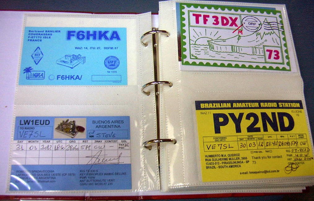
Having completed the transmitter just in time for Cycle 24's hoped-for great 10m conditions, it turned out that only a couple of one-week periods over the past three winters where good enough to reach Europe. During the two "double-peaks" I worked many dozens of Europeans, all of them in response to my crystal-controlled CQ's, mostly on 28.042kHz.
 |
| Courtesy: http://www.noaa.gov/ |
Nobody was more excited than I, the first time I heard a reply from Europe....it was from G4RRA who, as fate would have it, recorded my signal on that early October morning.

There were a few mornings when I had long pileups and worked Europe for several hours, most of the time shaking my head in disbelief that such a simple transmitter could provide so much DX pleasure...but really of course, it was mostly the great performance of Ten....the "other magic band".
I really doubt that 10m will once again support European conditions good enough for my one-tuber but it's still fun to work the U.S. With Cycle 24 on the decline I was happy to see that F2 has returned to Ten once again and this week I sparked-up the tri-tet to enjoy the propagation.
My chirpy return to the band produced many enjoyable QSO's..... NG2T (NY), KD8IFJ (MI), K9DP (IN), KA2MLH (NY), W4NA (VA), N4OW (FL), K8NS (FL), N5AF (TX), WA5AFD (OK), K5TIA (TX), K9DX (IL) and VE3IKV/m, boldly travelling along the freeway at 120kph!
So....if you hear a chirpy CQ just a smidgen below 28.042, please.... give me a call!
Will I be lucky enough to squeeze out one last winter of tri-tet fun before having to move down to 15 or 20m? Time will tell....but somehow it won't be quite the same as riding that delicate 10m ether over the pole to Europe, on just one tube.
Hunting For NDBs In CLE186
 | ||
| "LU" - 214kHz Abbotsford, B.C. Has been heard from W1-KH6 |
Yes, it's once again time for the monthly Co-ordinted Listening Event (CLE) for NDB hunters....the 186th event. These always interesting and popular affairs take place over three nights, with this one starting on Friday, Sept 26th at local noon and running until Monday, Sept 29th, local noon. CLE186 covers the frequency range of 350.0 to 369.9kHz only.
These listening events serve several purposes. They:
- determine, worldwide, which beacons are actually in service and on-the-air so the online database can be kept up-to-date
- determine, worldwide, which beacons are out-of-service or have gone silent since the last CLE covering this range
- will indicate the state of propagation conditions at the various participant locations
- will give you an indication of how well your LF/MF receiving system is working
- give participants a fun yet challenging activity to keep their listening skills honed
Final details can be found at the NDB List website, and worldwide results, for every participant, will be posted here a few days after the event.
The very active Yahoo ndblist Group is a great place to learn more about the 'Art of NDB DXing' or to meet other listeners in your region. There is a lot of good information available there and new members are always very welcome.
If you are contemplating getting started on 630m, listening for NDBs is an excellent way to test out your receive capabilities as there are several NDBs located near this part of the spectrum.
 |
| Courtesy: http://www.classaxe.com/dx/ndb/rna/ |
You need not be an ndblist member to participate in the CLEs and all reports, no matter how small, are of much value to the organizers. Reports may be sent to the ndblist or e-mailed to either myself or CLE co- ordinator, Brian Keyte (G3SIA).
Please...don't be shy and do give CLE186 a try....then let us know what NDB's can be heard from your location! Your report can then be added to the worldwide database.
630m Wilkinson Power Combiner
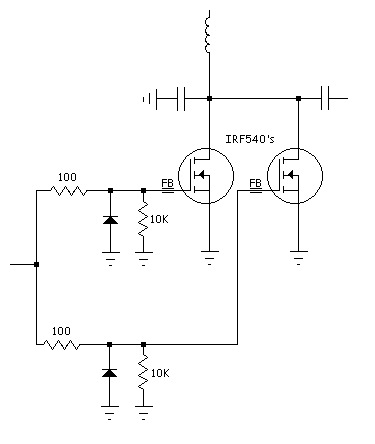
 It's often easier to achieve high power on 630m or LF by combining lower powered amplifiers than it is to build a single high-power rig. A simple Class D push-pull switching FET amplifier can readily produce 400-500W when operated in the 35V range. Combining two such amplifiers, both sharing a common oscillator / driver stage, would yield 800-1000W output...probably much more than needed on 630m.
 The low parts-count of the amplifier stage in the GW3UEP Class-E transmitter should easily produce 150-200W when run at a slightly higher drain voltage and proper heatsinking. Combining two such modules would yield 300-400W output at very low cost.
Combining can be done with a Two-Way (3-port) Wilkinson Splitter / Combiner. Splitters and Combiners are one and the same, depending on which ends are used for input(s) / output(s). When used in the 'combine' mode, insertion losses are virtually zero and mainly due to the miniscule resistive losses of the coils.

Combiner component values can be calculated the old fashioned way or by using one of the numerous online calculators. This excellent online video by Sebastian (KF5OBS) explains exactly how to calculate component values for the truly dedicated amongst us:
He also has a new video showing how to calculate values for combiners having more than two outputs, should you want to combine three or more individual amplifier modules.
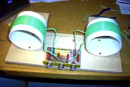
The first combiner I built was for my 2200m kW and combined the output of two 500W Class-D modules:

The air core coils are high-Q, cheap and easy to produce. If space is important, the inductors could just as easily be made using frequency-suitable powdered iron toroids, but at more expense. In actual operation, I have never been able to detect any heat from any of the combiner components, even when running a full kW at lengthy keydown periods of several minutes during QRSS transmissions, affirming the almost 'zero' insertion loss when used in the combining mode.
When I decided to use the same amplifier on 630m, a suitable circuit was designed and built for that band as well:
The terminating / balancing resistor (R) is used only as a safety device in case one of the two amplifiers fails during operation. It allows the still-working amplifier to safely dump some of its power into the load without destroying itself. Under normal operation, no current flows through this resistor so no power is wasted, assuming both inputs are equal. I have read of some schemes that will sense any current flow through 'R' and immediately shutdown the entire transmitter, thus allowing a resistor of lower dissipation to be used for 'R'.
Another benefit of the Wilkinson L-C Combiner is its filtering capability, as it works extremely well as a LPF. Neither my 2200m kW or 630m kW use any low-pass filtering other than that provided by the combiner's L-C network. It also seems to work well as a buffer of sorts, as both myself and VE7TIL noticed with our 2200m systems. We immediately stopped blowing FETs mysteriously when operating at full power. The amplifiers did not seem to react any longer to reactive components suddenly appearing in the antenna system or somewhere in the output network....everything was 100% more stable and reliable it seemed.
I can envision an exciting project consisting of a pair of GW3UEP finals feeding a toroid-based combiner, all in a very small footprint.
Should you choose to combine a pair of amplifiers for 630m, here are the values that were used in my own combiner:
C1 9.4nF
C2 4.7nF
L 23.5uH (13T on 4.25" OD PVC pipe)
R 100 ohm
More information on Wilkinson Combiners can be found here.
SKCC StraightKey Splendor
I was reminded this week of all the fun that the Straight Key Century Club (SKCC) guys are having when receiving a nice e-mail from Bill, W0EJ:
Steve,
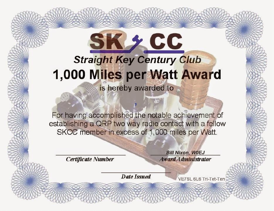
I have a question for you. The Straight Key Century Club has started to issue the 1,000 MPW Award and we are finalizing a certificate for the recipient to print off as we do for most of our awards. The majority of our certificates have a watermark that is usually some form of bug, straight key, or sideswiper.
For this QRP award certificate, would you object if we took your photo of your 6L6 tri-tet-ten transmitter and used it for a water mark? As a watermark, it would be faded and somewhat visible under the text on the certificate. We took the liberty of “drafting” a certificate to show you how it would look with the watermark of your 6L6.
We have another option, but your transmitter would be such a natural that I couldn't pass up asking to see if it would be OK with you to use an image.
In anticipation of your reply I thank you for your consideration.
73,
Bill - W0EJSince 2006, this 12,000 strong group of CW diehards have been doing their best to promote the magnificence of the mechanical key in everyday operation. With monthly operating events, awards, Elmering and an online sked page, there are plenty of fun activities for both newcomers and old hands to enjoy what was once the only way to send CW.
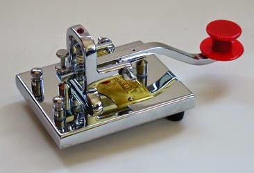
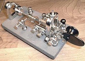
I can well recall tuning the CW bands as a newly-licenced teen in the mid 60's. Electronic keyers were just beginning to show up but the vast majority of amateurs still "pounded brass" with a straight key or with some type of bug. I held out for about two years before I parked my straight key and spent my Saturday job money on a brand new Vibroplex original, which I still use from time to time.
Getting back to Bill's mail....I was more than happy to grant permission to use the photograph of my little 6L6 Tri-Tet-Ten that I have had so much fun with over the past few winters on 10m CW during the peak of Cycle 24. I think their new 1000 Miles-Per -Watt award looks just great.....
....and here is what you need to do to earn one for your wall:
SKCC Introduces 1000 MPW Award
The SKCC is rolling out a 1,000 Miles per Watt Award, established to recognize the achievement of contacting another SKCC member using QRP power limits over longer distances.
A QSO must meet the qualifications of (Distance of QSO) / (Power Output in Watts) = 1,000 miles or more. Only the station applying for the award must operate at QRP levels. QSOs made on or after Sept. 1, 2014, are eligible.
For full details, see the award's main page.
Please check out the SKCC's homepage and consider signing-up...or drop by the K3UK SKCC Sked Page and get in on the fun....but, be sure to leave your keyer unplugged and enjoy some straight-key splendor!
GW3UEP 630m Tx Complete

Added to the panel were a 5A DC meter to monitor drain current, a keying jack and a key shorting-switch for keydown testing. This is the third version I have built using the design on Roger's page, with all three performing pretty much as advertised. It is an inexpensive, easily reproducible design.

I made one small change in the third version (above) by adding an additional FET in parallel with the single IRF540 thus cutting heating dissipation as described in an earlier blog. At normal CW keying speeds, no heatsinking seems needed on this particular version, when operated on 12VDC. Anything a little higher or any QRSS modes would require heatsinking. I did eventually add two small heatsinks in case I chose to run QRSS at some point.
When operated at 12-13V, the measured output power is around 25W while at 22-23V, the output is around 70W. I suspect that you could get in excess of 100W out, at higher voltages and larger heatsinking or by blowing the sink with a small fan.
The main function for the new transmitter will likely be as a semi-permanent beacon as well as for a small signal source when tuning the antenna. I may also use it in the WSPR mode with a modification to the oscillator section. One particularly nice feature with the Class-E design is that with no load at all, the current drops to almost zero, should the antenna suddenly fail.
If you live in VE7 or across the border in W7 land, please have a listen on 475.0 KHz and let me know if you can hear the "VVV" beacon over the next few days!
630m – Locked & Loaded

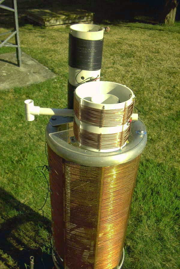
Several hours were spent yesterday finishing off the new 630m antenna matching transformer and installing the new loading coil with built-in variometer.
I decided to remove two turns from the bottom half of the coil, lowering the tuning range from 177-330uH to 165-313uH. Still not ideal but slightly more efficient. In reality, any losses from the variometer inefficiency are minuscule compared to the overall ground-system losses and probably unmeasurable. As it stands, the inverted 'L' resonates on 473kHz with 185uH of inductance and ideally the variometer should be operated closer to its total maximum inductance.
.jpg)
The new coil can be seen mounted on top of the much larger 2200m loading coil, a real monster by comparison. It was removed from one of the local NDB transmitters and saved from going to the scrap yard by an alert technician, who kindly donated it to me when I began operations on 2200m. I can only guess at what this must have cost to purchase when new, as the construction quality is superb.
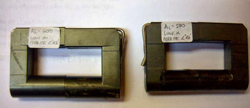
The new matching transformer is similar to the one that works so well on the 2200m system and wound on two TV flyback ferrite cores.
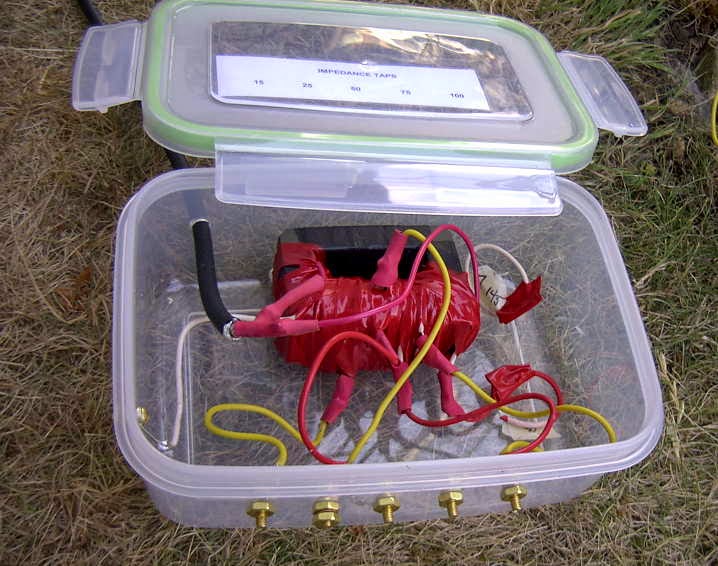
Once everything was cabled-up, I returned to the shack and plugged the coax into the KØLR antenna meter (VFO) and tuned it to 473kHz. I then went back to the variometer and tuned it while watching the meter through the shack window, looking for the sharp rise in current that would indicate resonance. I swept from one end to the other but saw no change! I eventually realized that I had not attached the antenna downlead to the top of the loading coil...duhh!
Once in place, the sweet-spot was quickly located and I returned to the shack to switch to the transmitter and scope match. For starters I had set the matching transformer to the 50ohm tap but the Scopematch indicated a resistive impedance of about 25 ohms. Moving to the 25 ohm tap resulted in a perfect match as can be seen here with both the current and voltage waveforms in exact phase and amplitude.

The Scopematch truly makes things easy, once you remember to attach the antenna!
The antenna tuning systems for 2200m and 630m are now separate and independent of each other, each with their own coaxial feedline and tuning system but I really wonder if I'll ever be active at all on 2200m again as there just appears to be no real interest amongst Canadian amateurs in our new 'topband'. It's really a shame since so many people worked very hard to obtain 2200m for Canadian amateurs...for me, its been a wonderful learning-ground for building and experimenting, as is 630m.
With the 630m system all ready to go at maximum EIRP, things are all set for the late October 630m Activity Night (hope you will be there). In the meantime, while awaiting new Canadian activity (come on guys!), I'm open for business.
Anyone wishing to try a two-way crossband contact please let me know. Both myself and VE7BDQ would love to work you!
LF Regen – Experimental Building Notes
 |
| Courtesy Roelof Bakker PAØRDT |
Anyone experimenting with the LF regen circuits described by Mike Tuggle and Roeloff Bakker in my recent "Tuggle-Style LF Regens" blog, might be interested in some helpful 'building notes' posted to the Yahoo ndblist by noted NDB/BCB DXer and exceptional RF guru, Steve Ratzlaff, AA7U of La Grande, Oregon.
..........
" Thanks to Mike Tuggle for his "1AD" (one active device) article using a dual gate Mosfet as the active device, and to Roelof Bakker's article about his own version of the 1AD I decided to build one too. I wanted to keep to the true 1AD configuration (no extra amplification) if possible. Mike uses very sensitive soundpowered headphones from the World War II era but those are very scarce to find in usable conditions these days. I was hoping to find an alternative set of phones that could be used but still not have to add an amplifier stage. I believe I have found a source of phones that can be currently purchased that are sensitive enough for the LF 1AD receiver.
Mike uses a Siemens 1216 Mosfet that he obtained from junked TV UHF tuners, but that particular transistor is no longer available. My first thing was to purchase a variety of Mosfets of other types and test them on the bench to see if they might be suitable. I bought one or two of all the Mosfet types available from this non-eBay US seller, Scott Lowe. (He used to sell on eBay but now only sells through his own webpage. And while checking the URL I notice it's now listed as Mike Lowe instead of the previous Scott Lowe--I don't know why the change.)
http://www.angelfire.com/electronic2/index1/
So I got the dual gate Mosfet types 40673, BF981, 3SK88, MFE201, BF960, BF961, BF998, 3N211 to try. When I mentioned this project to Mike Tuggle he was extremely generous to send me one of his rare Siemens 1216 Mosfets to test along with some other Mosfets he'd been saving for years. Thanks Mike! I bought five BF966 Mosfets from an eBay seller in Italy, so I was able to test the same type Roelof is using too. (The eBay seller of the BF966's seller name is "radionova22" and current item number for five BF966's is 331079146309, for $1.00 plus shipping ($10 for me in Oregon). He shipped immediately, and it took about 10-12 days for me to receive the small padded envelope. My one experience with this seller was 100% positive.) Note that almost all, if not all, Mosfets are diode-protected on the gates, and are more or less insensitive to handling static damage. But most sellers will ship the Mosfet in a static-protective wrapping. The Italian eBayer does not do this. But the couple BF966's I tried in my sensitivity test worked fine, thus were not damaged by any lack of antistatic shielding. I always use antistatic methods if I build something with Mosfets or anything that might be sensitive to static damage, and I recommend you do the same. At the minimum that means sit perfectly still while you're handling the Mosfet, don't shuffle your feet. Try to touch a grounded object before handling the device. In the US that could be as simple as a wire attached to the third wire/ground on the AC outlet powering your soldering iron that you can touch first. More elaborate would be an antistatic mat and an antistatic wrist strap all connected to the third wire ground of the AC outlet. Most modern soldering irons use a 3-wire AC cord with the actual metal of the soldering iron connected to the third wire ground, but I don't recommend you try to touch the very hot metal soldering iron part to obtain your antistatic ground!
I built the LF regen toroid version that Roelof used, and used the diode source bias that Mike and Roelof used and used my existing USI soundpowered phones (also now rare to find) with the Bogen T725 audio transformer and tested each Mosfet on the bench for sensitivity. I used a calibrated signal generator at mid-band, 300 kHz, reducing level to the faintest level I could detect. Initially I used Roelof's Gate 2 separate bias circuit, but soon found that I got the same sensitivity with no separate Gate 2 adjustment needed (using Mike's circuit of tying both gates together) and that's what I used for all the sensitivity tests. What I found was that all the Mosfets were more or less equally sensitive, within a dB or two, if they would work in the circuit. Not every Mosfet would work, that is would give proper regeneration when the Regen control was varied, and detect a signal--a few types did not work at all. Perhaps they would work with separate Gate 2 bias but I didn't try that to see if they might work. The ones that did not work were the 3SK88, MFE201 and the 3N211 made by Siliconix. Mike's selection of Mosfets included a 3N211 made by Texas Instruments, and oddly that one worked fine and was equally as sensitive as the other Mosfets that did work. So the good news is if you select a Mosfet from the ones I tried that worked, then you don't have to worry about one Mosfet being more sensitive than another. That list is the BF960, BF961, BF966, BF981, BF998, 40673 (and Mike's own "unobtainable" Siemens 1216). Note the BF998 is a surface mount part, very tiny, and will require you to use magnification and some ingenuity in order to solder wires to it. I was able to solder thin #30 silverplated wire stripped from #30 wirewrap wire but it took a number of attempts to get the three wires on (both gates are tied together and both gates are on the same side of the package making it slightly easier). Using my sensitive USI phones I was able to get -135 dBm sensitivity--that was the faintest signal I could hear, for my sensitivity test for the Mosfets.
A eBay seller in the San Francisco, California area, Ming, who some of us buy our Litz wire from, also advertises some Chinese soundpowered phones and one regular magnetic headphone. Since he's been advertising them for years he apparently has a ready supply of them from China, and I bought a pair of each of his phones to try with the idea that maybe these phones would prove sensitive enough to use in the 1AD LF set without having to add a stage of amplification. I did another bench sensitivity test similar to the Mosfet test. I compared the sensitivity of my own USI phones with these phones. As for the Mosfet test, the USI phones gave -135 dBm sensitivity. Ming's non-soundpowered 4400 ohm phones gave -125 dBm; Ming's soundpowered EH-3 phones gave -120 dBm; Ming's soundpowered EH-5 phones gave the same -120 dBm sensitivity. (Ming told me he sometimes can get one other model of Chinese soundpowered phones, but he doesn't advertise them since he only gets limited quantities. He sold me a set of them to try, Model SH-091A which tested at -130 dBm. Perhaps you could ask Ming if he has any currently available, and if so, what the price is.)
Perhaps I should say something about the units I'm using for sensitivity. "DBm" stands for "decibels referred to one milliwatt across 50 ohms". 50 ohms is the standard impedance for test equipment in non-telecommunications industry (75 ohms is the standard for telecommunications). The larger the number, in negative terms, the lower the signal from the generator to give the sensitivity in my tests. So, -135 dBm is 5 decibels lower (for my USI phones) than the next most sensitive phones, -130 dBm for the SH-091A phones. For power measurements in decibels, every 3 decibels (dB) change, the power is cut in half (or doubled if going up in power). So ideally for the 1AD you want to use the phones that are the most sensitive.
But in the real world of LF, the external noise is high even if you happen to live in a location of low AC noise, and my most recent tests have been to see if one of Ming's readily available phones would work about as well as my more sensitive USI phones.
Something else to consider is one needs to use an audio transformer with soundpowered phones, in order to match their relatively low impedance to the higher impedance of the output signal at the drain of the Mosfet. That's what the Bogen T725 transformer that Mike uses does, and the transformer that Roelof uses. But one of the phones Ming offers is a non-soundpowered type that already has relatively high impedance, the 4400 ohms phones. Using that, no audio transformer is needed, which simplifies the 1AD circuit, as long as these 4400 ohms phones are sensitive enough with the 1AD. I've been testing this 1AD configuration for the past 5 days, on real NDB signals from my antenna and believe that these phones are sensitive enough. So using them, one takes the output at the Mosfet drain and 0.001 uF bypass capacitor directly to one of the 4400 ohms phones leads and the other phones lead goes to the +9 volts (where the top of the Bogen T725 transformer would normally go).
I've been using my active whip antenna with my 1AD and that works very well. Roelof uses his standard Mini-Whip with his own 1AD. Mike uses a high impedance wire antenna for all his 1AD listening and has his own tuner he's developed to feed his 1AD consisting of a series inductor and variable capacitor with the antenna link on the 1AD. The inductor (about 2600 microhenries) has one end to the antenna and the other end to the 1AD antenna link with the other end of the antenna link to the series variable capacitor (about 1000 pF) with the other side of the capacitor to ground.
Scott Lowe's webpage has a bunch of electronics parts stuff. My own 1AD is currently using a custom two-section high capacity miniature polyvaricon variable capacitor that he offers. He has a knob to go with it as a separate item. I'm using the switched capacitor arrangement that Roelof shows in his diagram and the same fixed capacitors. The idea is to separate the NDB band into two sections and to reduce how far up in frequency the tuning goes. If you use a similar capacity variable capacitor, the two fixed values (300 pF and 100 pF) work well. You want some overlap in tuning for the two switched sections. My own 1AD has about 8-10 kHz overlap. You don't want "underlap" which means the lower section stops, say at 310 kHz, and the upper section starts at say, 315 kHz, which would leave a gap of 5 kHz where you couldn't tune the radio in that section. The Scott Lowe polyvaricon is labeled as "dual 335 pF and 20 pF plastic variable capacitor" that I'm using. He includes a sheet for the pinouts of the various sections. We only want to use the two 335 pF sections. I find this capacitor is (just barely) adequate for use in the 1AD, with the dual section switching arrangement. By that I mean I can turn the shaft and get enough resolution to smoothly tune in fine increments without jumping over frequencies. A larger knob than is offered would help, but the "larger knob" option that Scott Lowe offers (it's not really a large diameter knob!) works. It takes some careful tuning with thumb and forefinger but I don't have any major problems tuning. Of course a "proper" much larger variable capacitor, especially with a vernier drive, would be far more preferable (like Mike and Roelof use). But I'm suggesting that one could build a pretty inexpensive LF 1AD radio using readily available parts, using Ming's 4400 ohms phones which don't require an audio transformer.
I used toroid that Roelof gives in his article, FT140-61 with the specified turns. That worked fine. I had a smaller FT114-61 toroid I used and that worked equally well. In North America both these can be obtained from Diz at www.kitsandparts.com. (He also ships internationally.) I used #24 wire for the main coil on the FT140-61. For the FT114-61 I used smaller #30 silverplated wirewrap wire, with 88 turns, about 9 feet of wire. Regen winding 5 turns; antenna winding two turns. For both, I wound the Regen winding next to the ground end of the primary winding. Of course proper phasing is needed for the Regen winding.
Ming's eBay items can be found by searching for his seller name "mkmak222" in the advanced search options under "seller". The 4400 ohms phones I bought are called "NOS Military 4400 ohm Headset for Crystal radio, ham". The picture shows a banana plug on the end of the cord. He has another 4400 ohm headset also listed but I didn't try that--it has a phone jack on the cord--I don't know if it's the same sensitivity as this one. Current eBay item number for the one I tried is 161409812818; price is $24.99 plus shipping. (He also has a very good ferrite audio transformer with a wider range of taps than the Bogen T725, if you're using soundpowered phones.) Of course you can see all the items he sells by clicking on the "See other items" on any of his eBay ads.
I live about one mile from my local NDB, 296 LGD. It only causes some problems from extremely strong signal strength (which isn't adjustable on the 1AD) within about +/-25 kHz or less. Once the 1AD is set to proper regeneration the Q of the tuning inductor is high enough that outside that tuning range LGD isn't a problem. It can still be heard sometimes way down in the background until you tune far enough away. Even tuned very close to it, just the actual headphone level is the main problem. I have a BCB station about 6 miles away which is quite a bit stronger in actual signal level. That causes some mixing products here and there in the NDB range, but those are on some even 10 kHz frequencies. If you're in an urban area with a bunch of AMBC stations, perhaps you'd have more problems with the 1AD or may need to think about how to maybe add a lowpass filter in front of the set.
One last comment, about winding lots of turns on a toroid. I use a homemade stiff cardboard bobbin that I wind the wire on then use the bobbin to wind the actual toroid turns. This makes for fast winding where lots of turns are needed compared to pulling a long length of wire through the toroid core for each turn, without the bobbin. The bobbin I used is about 4" long x 1/2" wide with a 1/4" notch cut in each end where the wire is wound. (The bobbin width of course has to be narrower than the inside diameter of the toroid and the length is generally several inches or more, depending on size of toroid and length of wire/number of turns to be wound.)
Good luck with making your own 1AD if you decide to do so; I've tried to give some ideas on how you can buy current products that will work for a true 1AD configuration. Please let ndblist know of your results if you build one! "
Steve adds that so far, in just a few nights of casual listening (and under not so good conditions) he has logged 104 NDB's using a small homebrew active whip!
Thanks for all of the great tips Steve.
Mike uses a Siemens 1216 Mosfet that he obtained from junked TV UHF tuners, but that particular transistor is no longer available. My first thing was to purchase a variety of Mosfets of other types and test them on the bench to see if they might be suitable. I bought one or two of all the Mosfet types available from this non-eBay US seller, Scott Lowe. (He used to sell on eBay but now only sells through his own webpage. And while checking the URL I notice it's now listed as Mike Lowe instead of the previous Scott Lowe--I don't know why the change.)
http://www.angelfire.com/electronic2/index1/
So I got the dual gate Mosfet types 40673, BF981, 3SK88, MFE201, BF960, BF961, BF998, 3N211 to try. When I mentioned this project to Mike Tuggle he was extremely generous to send me one of his rare Siemens 1216 Mosfets to test along with some other Mosfets he'd been saving for years. Thanks Mike! I bought five BF966 Mosfets from an eBay seller in Italy, so I was able to test the same type Roelof is using too. (The eBay seller of the BF966's seller name is "radionova22" and current item number for five BF966's is 331079146309, for $1.00 plus shipping ($10 for me in Oregon). He shipped immediately, and it took about 10-12 days for me to receive the small padded envelope. My one experience with this seller was 100% positive.) Note that almost all, if not all, Mosfets are diode-protected on the gates, and are more or less insensitive to handling static damage. But most sellers will ship the Mosfet in a static-protective wrapping. The Italian eBayer does not do this. But the couple BF966's I tried in my sensitivity test worked fine, thus were not damaged by any lack of antistatic shielding. I always use antistatic methods if I build something with Mosfets or anything that might be sensitive to static damage, and I recommend you do the same. At the minimum that means sit perfectly still while you're handling the Mosfet, don't shuffle your feet. Try to touch a grounded object before handling the device. In the US that could be as simple as a wire attached to the third wire/ground on the AC outlet powering your soldering iron that you can touch first. More elaborate would be an antistatic mat and an antistatic wrist strap all connected to the third wire ground of the AC outlet. Most modern soldering irons use a 3-wire AC cord with the actual metal of the soldering iron connected to the third wire ground, but I don't recommend you try to touch the very hot metal soldering iron part to obtain your antistatic ground!
I built the LF regen toroid version that Roelof used, and used the diode source bias that Mike and Roelof used and used my existing USI soundpowered phones (also now rare to find) with the Bogen T725 audio transformer and tested each Mosfet on the bench for sensitivity. I used a calibrated signal generator at mid-band, 300 kHz, reducing level to the faintest level I could detect. Initially I used Roelof's Gate 2 separate bias circuit, but soon found that I got the same sensitivity with no separate Gate 2 adjustment needed (using Mike's circuit of tying both gates together) and that's what I used for all the sensitivity tests. What I found was that all the Mosfets were more or less equally sensitive, within a dB or two, if they would work in the circuit. Not every Mosfet would work, that is would give proper regeneration when the Regen control was varied, and detect a signal--a few types did not work at all. Perhaps they would work with separate Gate 2 bias but I didn't try that to see if they might work. The ones that did not work were the 3SK88, MFE201 and the 3N211 made by Siliconix. Mike's selection of Mosfets included a 3N211 made by Texas Instruments, and oddly that one worked fine and was equally as sensitive as the other Mosfets that did work. So the good news is if you select a Mosfet from the ones I tried that worked, then you don't have to worry about one Mosfet being more sensitive than another. That list is the BF960, BF961, BF966, BF981, BF998, 40673 (and Mike's own "unobtainable" Siemens 1216). Note the BF998 is a surface mount part, very tiny, and will require you to use magnification and some ingenuity in order to solder wires to it. I was able to solder thin #30 silverplated wire stripped from #30 wirewrap wire but it took a number of attempts to get the three wires on (both gates are tied together and both gates are on the same side of the package making it slightly easier). Using my sensitive USI phones I was able to get -135 dBm sensitivity--that was the faintest signal I could hear, for my sensitivity test for the Mosfets.
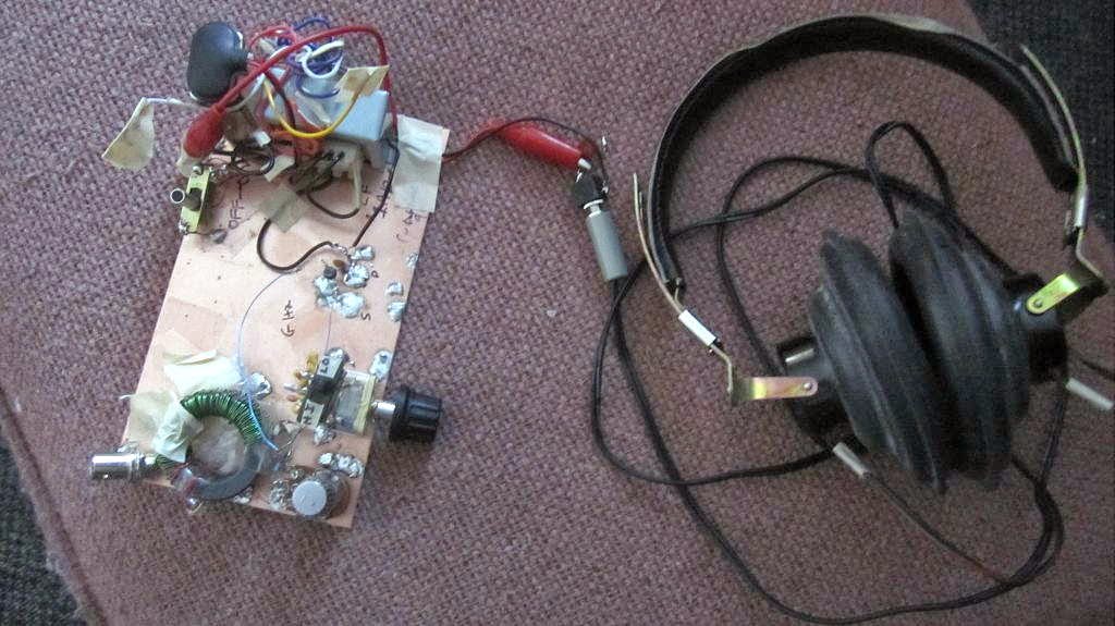 |
| Steve's Testbed Regen |
Perhaps I should say something about the units I'm using for sensitivity. "DBm" stands for "decibels referred to one milliwatt across 50 ohms". 50 ohms is the standard impedance for test equipment in non-telecommunications industry (75 ohms is the standard for telecommunications). The larger the number, in negative terms, the lower the signal from the generator to give the sensitivity in my tests. So, -135 dBm is 5 decibels lower (for my USI phones) than the next most sensitive phones, -130 dBm for the SH-091A phones. For power measurements in decibels, every 3 decibels (dB) change, the power is cut in half (or doubled if going up in power). So ideally for the 1AD you want to use the phones that are the most sensitive.
But in the real world of LF, the external noise is high even if you happen to live in a location of low AC noise, and my most recent tests have been to see if one of Ming's readily available phones would work about as well as my more sensitive USI phones.
Something else to consider is one needs to use an audio transformer with soundpowered phones, in order to match their relatively low impedance to the higher impedance of the output signal at the drain of the Mosfet. That's what the Bogen T725 transformer that Mike uses does, and the transformer that Roelof uses. But one of the phones Ming offers is a non-soundpowered type that already has relatively high impedance, the 4400 ohms phones. Using that, no audio transformer is needed, which simplifies the 1AD circuit, as long as these 4400 ohms phones are sensitive enough with the 1AD. I've been testing this 1AD configuration for the past 5 days, on real NDB signals from my antenna and believe that these phones are sensitive enough. So using them, one takes the output at the Mosfet drain and 0.001 uF bypass capacitor directly to one of the 4400 ohms phones leads and the other phones lead goes to the +9 volts (where the top of the Bogen T725 transformer would normally go).
I've been using my active whip antenna with my 1AD and that works very well. Roelof uses his standard Mini-Whip with his own 1AD. Mike uses a high impedance wire antenna for all his 1AD listening and has his own tuner he's developed to feed his 1AD consisting of a series inductor and variable capacitor with the antenna link on the 1AD. The inductor (about 2600 microhenries) has one end to the antenna and the other end to the 1AD antenna link with the other end of the antenna link to the series variable capacitor (about 1000 pF) with the other side of the capacitor to ground.
Scott Lowe's webpage has a bunch of electronics parts stuff. My own 1AD is currently using a custom two-section high capacity miniature polyvaricon variable capacitor that he offers. He has a knob to go with it as a separate item. I'm using the switched capacitor arrangement that Roelof shows in his diagram and the same fixed capacitors. The idea is to separate the NDB band into two sections and to reduce how far up in frequency the tuning goes. If you use a similar capacity variable capacitor, the two fixed values (300 pF and 100 pF) work well. You want some overlap in tuning for the two switched sections. My own 1AD has about 8-10 kHz overlap. You don't want "underlap" which means the lower section stops, say at 310 kHz, and the upper section starts at say, 315 kHz, which would leave a gap of 5 kHz where you couldn't tune the radio in that section. The Scott Lowe polyvaricon is labeled as "dual 335 pF and 20 pF plastic variable capacitor" that I'm using. He includes a sheet for the pinouts of the various sections. We only want to use the two 335 pF sections. I find this capacitor is (just barely) adequate for use in the 1AD, with the dual section switching arrangement. By that I mean I can turn the shaft and get enough resolution to smoothly tune in fine increments without jumping over frequencies. A larger knob than is offered would help, but the "larger knob" option that Scott Lowe offers (it's not really a large diameter knob!) works. It takes some careful tuning with thumb and forefinger but I don't have any major problems tuning. Of course a "proper" much larger variable capacitor, especially with a vernier drive, would be far more preferable (like Mike and Roelof use). But I'm suggesting that one could build a pretty inexpensive LF 1AD radio using readily available parts, using Ming's 4400 ohms phones which don't require an audio transformer.
I used toroid that Roelof gives in his article, FT140-61 with the specified turns. That worked fine. I had a smaller FT114-61 toroid I used and that worked equally well. In North America both these can be obtained from Diz at www.kitsandparts.com. (He also ships internationally.) I used #24 wire for the main coil on the FT140-61. For the FT114-61 I used smaller #30 silverplated wirewrap wire, with 88 turns, about 9 feet of wire. Regen winding 5 turns; antenna winding two turns. For both, I wound the Regen winding next to the ground end of the primary winding. Of course proper phasing is needed for the Regen winding.
Ming's eBay items can be found by searching for his seller name "mkmak222" in the advanced search options under "seller". The 4400 ohms phones I bought are called "NOS Military 4400 ohm Headset for Crystal radio, ham". The picture shows a banana plug on the end of the cord. He has another 4400 ohm headset also listed but I didn't try that--it has a phone jack on the cord--I don't know if it's the same sensitivity as this one. Current eBay item number for the one I tried is 161409812818; price is $24.99 plus shipping. (He also has a very good ferrite audio transformer with a wider range of taps than the Bogen T725, if you're using soundpowered phones.) Of course you can see all the items he sells by clicking on the "See other items" on any of his eBay ads.
I live about one mile from my local NDB, 296 LGD. It only causes some problems from extremely strong signal strength (which isn't adjustable on the 1AD) within about +/-25 kHz or less. Once the 1AD is set to proper regeneration the Q of the tuning inductor is high enough that outside that tuning range LGD isn't a problem. It can still be heard sometimes way down in the background until you tune far enough away. Even tuned very close to it, just the actual headphone level is the main problem. I have a BCB station about 6 miles away which is quite a bit stronger in actual signal level. That causes some mixing products here and there in the NDB range, but those are on some even 10 kHz frequencies. If you're in an urban area with a bunch of AMBC stations, perhaps you'd have more problems with the 1AD or may need to think about how to maybe add a lowpass filter in front of the set.
One last comment, about winding lots of turns on a toroid. I use a homemade stiff cardboard bobbin that I wind the wire on then use the bobbin to wind the actual toroid turns. This makes for fast winding where lots of turns are needed compared to pulling a long length of wire through the toroid core for each turn, without the bobbin. The bobbin I used is about 4" long x 1/2" wide with a 1/4" notch cut in each end where the wire is wound. (The bobbin width of course has to be narrower than the inside diameter of the toroid and the length is generally several inches or more, depending on size of toroid and length of wire/number of turns to be wound.)
Good luck with making your own 1AD if you decide to do so; I've tried to give some ideas on how you can buy current products that will work for a true 1AD configuration. Please let ndblist know of your results if you build one! "
Steve adds that so far, in just a few nights of casual listening (and under not so good conditions) he has logged 104 NDB's using a small homebrew active whip!
Thanks for all of the great tips Steve.


