 |
 630m Loading Coil & Variometer Update

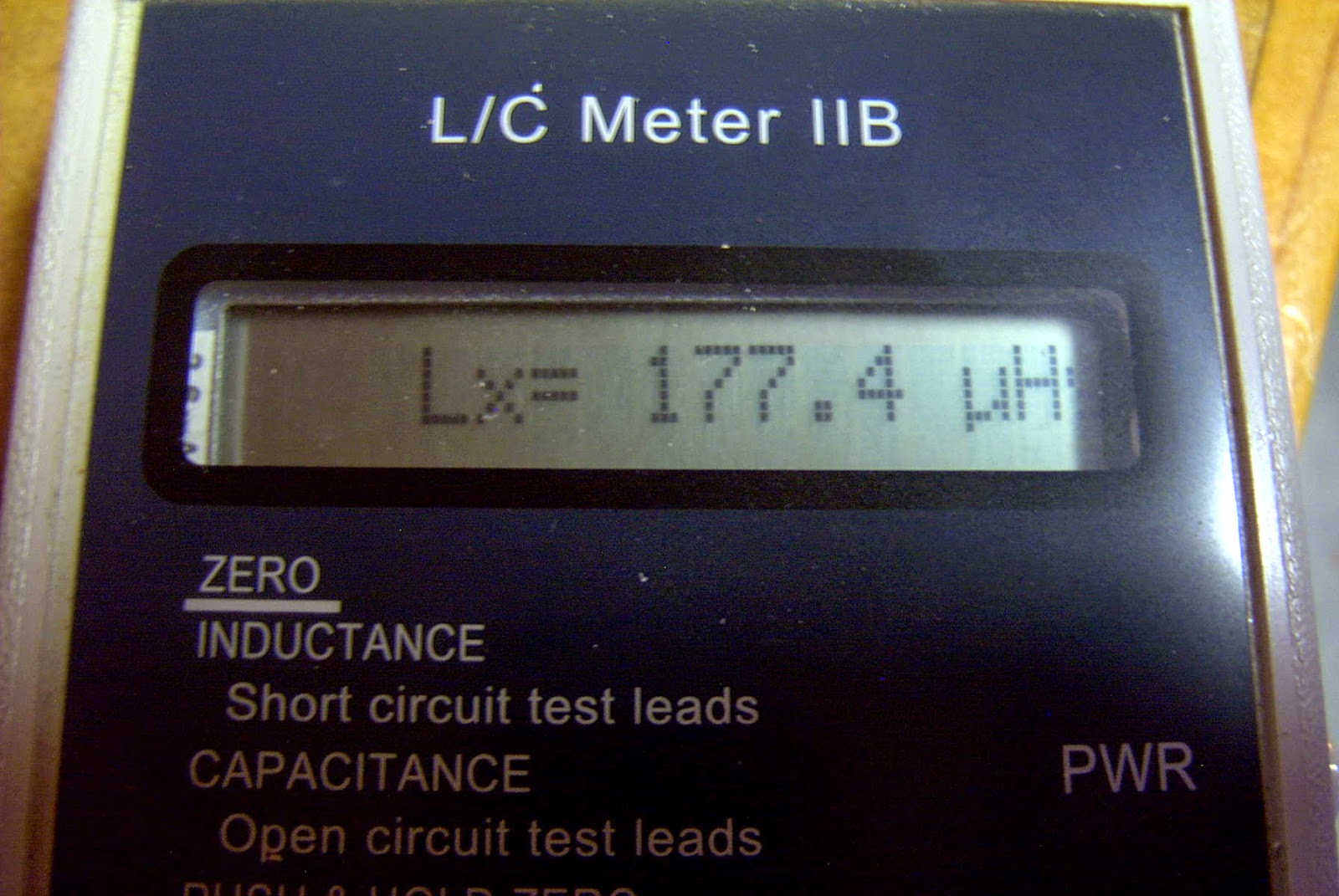
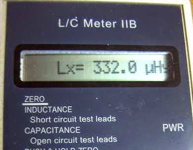
Originally planning for something in the 130-230uH range, the final result produced 177-332uH...certainly more than enough and perhaps a little too much more. I may end up removing a few turns from the main coil as apparently the best variometer efficiency is realised when operated towards the maximum end of inductance, rather than at the low end or when the inner coil is bucking the main coil.

 |
| Source: http://www.alg.myzen.co.uk/radio/136/ant_xformer.htm |
 | ||
| Source: http://www.alg.myzen.co.uk/radio/136/ant_xformer.htm |
 |
| Source: http://leoricksimon.blogspot.ca/2007/05/flyback-driver.html |
4 Responses to “630m Loading Coil & Variometer Update”
Please support our generous sponsors who make AmateurRadio.com possible:
 Ham Radio Deluxe |
 W5SWL Electronics |
 Ham Radio Prep |
 KB3IFH QSL Cards  Hip Ham Shirts  HamRadioAuctions HamRadioAuctions Reliance Antennas Reliance Antennas Enigma Shop Enigma Shop |  morseDX  Ni4L Antennas  R&L Electronics R&L Electronics antennas.us antennas.us QRV QRV |
- Matt W1MST, Managing Editor

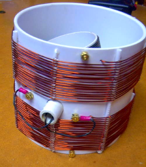
Could you give us more details on the variometer. In particular, how you handle getting the leads from the inner coil, or are you just depending on their flexibility? Stranded wire?
Thanks!
73 /paul W3FIS
Hi Paul….the inner coil is made of multi-strand #18 and is covered with a PVC jacket. The ends of the coil are secured through a set of small holes drilled into the 3.25″ form and then each wire end is threaded through a pair of holes that has been drilled into the rotating shaft. You can see the two wires emerging from the end of the shaft in one of the photos. I have left a fair bit of slack to allow for rotation but in actual operation, there is not a lot of tuning involved once the proper spot has been found. There might be a minor tweak once in awhile, especially if making a large QSY from one end of the band to the other but if it is anything like my 2200m system, not a lot of tuning is required once it has been set. I find that the impedance changes more than the resonance, from season to season, and I always need to change the impedance tap on the matching transformer several times a year as the ground conductivity changes.
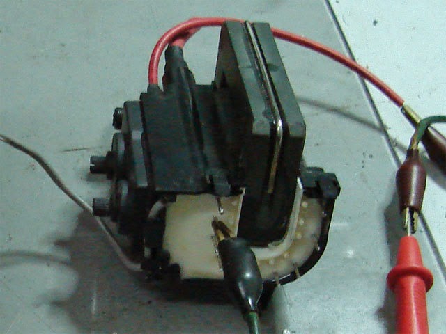
On those flyback transformers the two pieces of ferrite are usually hold together by a metal clamp – like on the picture above – fixed with some hot glue. With old TV sets the glue had dried enough that removing the clamp is not difficult. Wiggle a screwdriver under one end of the clamp and carefully lift it up, then slide it off. The ferrite can then be removed. It takes me less than a minute, but finding an old TV set takes a lot more time, unfortunately.
I’m sorry to be a nuisance, but I’ve had to move my web pages to a new domain. I’d be grateful if you could update the ‘GW4ALG’ link above (three places) to:
https://www.4alg.uk/radio/136/ant_xformer.htm
With best wishes
Steve G(W)4ALG