Author Archive
 Time to make a choke balun

In your ham radio adventures, you may have heard the words..choke balun, feedline isolation, common mode choke or a 1:1 balun. In my humble opinion different names for the same device. These devices for the most part are present in a system to control common mode currents. I am not an engineer just a simple ham guy trying to sometimes understand some very complicated and technical explanations.
I hope to keep the next bunch of lines understandable. Here we go...what are common mode currents! Most ham use some form of 52 ohm coax as it's very easy to route, secure and can within reason be placed anywhere. Ideally, RF will flow out on the OUTER SURFACE of the coax INNER CONDUCTOR and flow back on the INSIDE SURFACE of the coax shield. This is what happens in a perfect world but if a system is unbalanced RF current will return on the OUTSIDE of the outer coax braid. It does not return but it radiates.

This is when we hams can experience RFI issues and these issues vary with the amount of common mode currents flowing on the outside of the shield of the coax. How does one control this common mode current? One very effective way is to introduce a common mode choke, 1:1 balun, choke, feed line isolation or whatever else it could be called.
In a previous post, I did go over how I installed a 1:1 balun at the antenna feed point of my Hustler 4BTV and that seemed to satisfy my RFI issues but further reading informed me that a choke balun at the radio feed point would be very advantageous. I ordered 2 FT240-31 mix toroids as I decided to make a choke balun instead of buying one. The two common mixes for HF toroids are 31 and 43. The difference being the 31 mix is effective from 1-300 Mhz and 43 is effective from 25-300 Mhz. I chose to go with the 31 mix and purchased 2 from a reputable dealer as not all toroids are created equal. I would be very wary if you find toroids at a very low price....just remember you get what you pay for. I ordered mine from Mouser Electronics Canada, part number 623-2631803802 made by Fair-Rite for 13.00 each.

I used RG8X coax to wind around the toroid but the issue with using a ring toroid compared to a split bead is I had to remove the PL-259 to wind the coax around the toroid and then solder the PL-259 back on. I intended to make 10 loops and for some reason, I ended up with 11 turns through the toroid. I then soldered the PL-259 connector back on but not before placing the barrel and coax spacer on....how many of us have soldered a PL-259 on and then realized we forgot the spacer and barrel!
Another advantage to having a choke balun at each end of the coax is that it helps remove some RF noise that is picked up on the shield of the coax.
 |
| Dont forget these BEFORE soldering the PL-259 |
Hustler 4BTV base cover.
 |
| Lower section before balun install. |
Autumn is here along with the leaves all over the lawn, once or twice a week I take the lawn mower out with the grass catcher on and vacuum the lawn of leaves. Doing this got me thinking of winter and my Hustler 4BTV antenna regarding the snow. I did some internet searches and some left the base alone while others covered it. The conscience was that snow does not bother the vertical with regards to performance but I was concerned about the connections and isolation balun.
I decided to make a box to cover the base section of the antenna but one that could easily come off in case of a storm and I had to lower the antenna. I wanted something simple, that would stand up to the weather and remove without issue. I came up with a cover made of wood and only 4 deck screws had to be removed to remove the box cover from the antenna for storage. The top also has 4 deck screws it can be removed for access to the antenna if it has to be taken down due to high winter winds.
I also made the box with room on the side as I knew I would be adding the choke balun to the mix. It's going to be painted white to mix in with the snow when it comes and I will keep on top of shovelling the snow on and around it just in case the antenna has to come down due to windy weather.
As said before to remove the box ultimately all that has to be done is 4 deck screws removed and the side cover and half of the top cover comes off and the box can be removed and stored for the summer. In case of poor winter weather, 2 deck screws are removed and half of the top cover is removed and the antenna base is exposed.
 |
| Room for the Balun |
 |
| Completed box to be painted |
The final picture shows 1/2 of the top cover removed and the lower screw clamp is exposed and can be loosened for the antenna to be removed. The cover goes back in place.

Read the rest of this entry »
Time to add a balun.

When I moved to the East coast from Ontario at the new QTH I purchased and installed an EndFed antenna and it worked great for me. It was a huge step up from the condo balcony mag loop antenna. The EndFed is a compromise-type antenna and does come with some issues. The main issue is (if you don't use a counterpoise) the coax shield is used as the counterpoise. This can cause some issues and an isolation balun is needed in the shack. I purchased a quality isolation balun from balun designs to take care of the feed line issues. In time I did install a counterpoise but it's not that effective when your Endfed goes from 10m-80m.
I still had some RFI issues in the shack that ferrites did an excellent job in looking after. I still had some off-and-on issues with our electronic washing machine, the motion sensor light on the shed and some Google home devices. I then moved from the EndFed to a vertical antenna the Hustler 4BTV antenna. In the manual for the 4BTV, it is advised if you have any RFI issues due to the coax radiating RF place an isolation balun at the antenna. It seemed as time passed I was issue free. 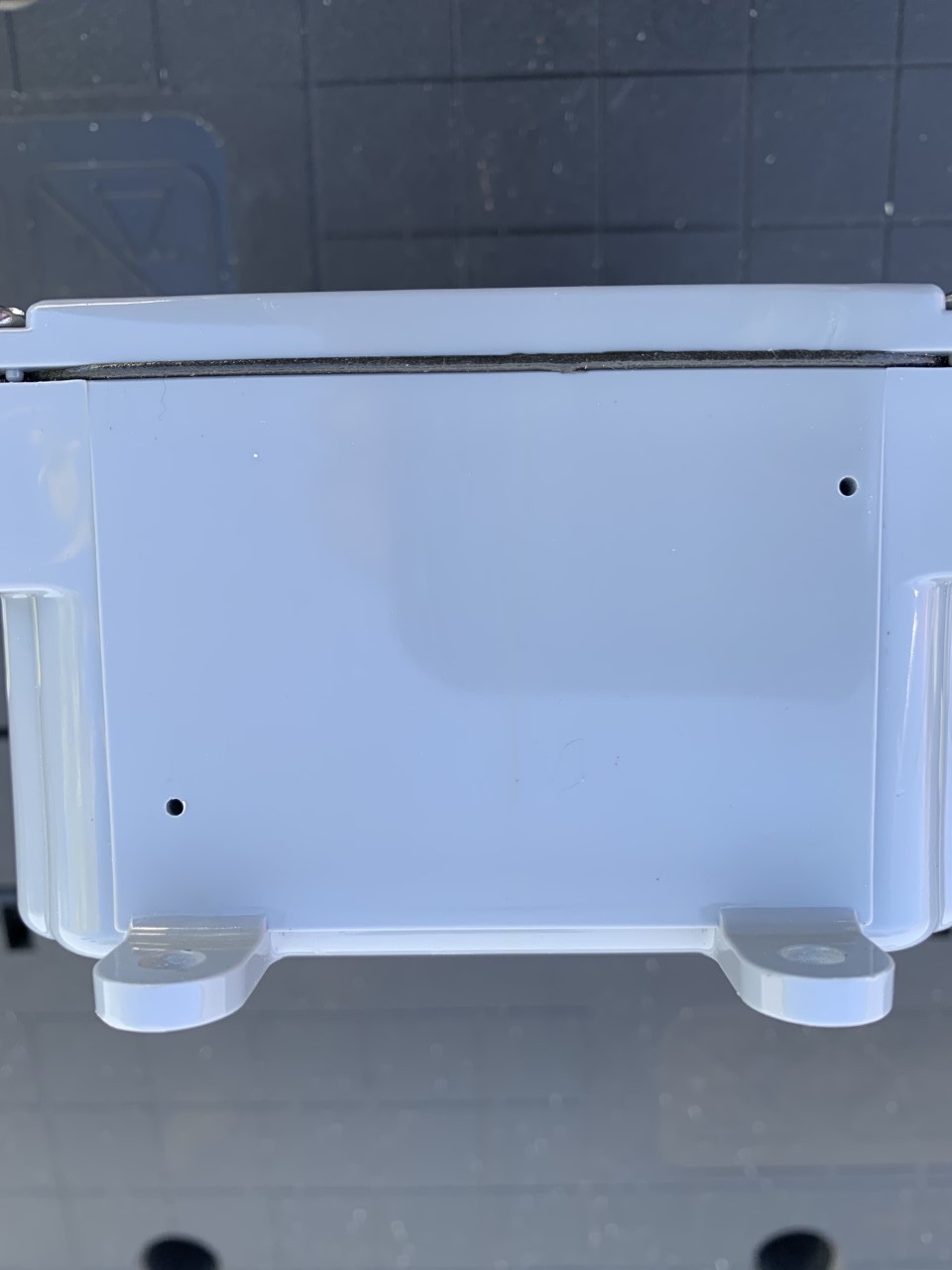
Drainage holes 1/16th
Now and then I started to notice while operating my Icom 7610 in CW mode I would have my N1MM contest program lock up. There was no rhyme or reason as to when this happened, what power level and what band I was on. I could make it through a CWops mini-test of an hour with no issues. The next CWops mini contest I had nothing but issues. I also noticed when using my VPN on the PC I would have the VPN disconnect and then reconnect messages coming up as I transmitted. I was reading online when coax radiates RF it can be very hit-and-miss as to when it happens and what is affected each time. This sounded like the issue I was having and I decided to place the isolation balun at the base of the 4BTV vertical.
Once the isolation balun was installed I am RF free and have been for over a month now. My electronic washing machine, N1MM logger and VPN connection have no problems. 
Waterproof connections
I had to take into consideration some precautions when putting the isolation balun outdoors. It was recommended to drill 2 1/16 holes in the bottom so any condensation would not build up inside. Also around all PL-259 connections, I waterproofed them with self-amalgamating tape.
A weekend of CW

If you were on the radio this weekend and are a CW buff then you know some QSO parties were in full swing along with the WAG (worked all Germany) contest were on. Since my blog title has changed to "The world of CW" you may have guessed that I was involved in something by the way of CW this weekend.
I decided to join in on the WAG contest, it's always very well attended, starts Saturday noon my time and ends Sunday noon. The German ops are great at CW and it gives me more practice at running in a CW contest. For the first time, I had no Murphy moments, no RF getting into anything to cause me side issues it sure was a nice change. I will be blogging in the near future as to what I ended up doing to get rid of my what seemed never ending surprise RF issues.
In the picture above it shows how I use the Icom 7610 in contests.
- I have 2 band scopes up (VFO A and VFO B) at the same time the operating band (top slice) and the is it open yet band (bottom slice)
- On the left-hand side tabs you will see "BK-IN FULL" or full break-in turned on. This allows me while calling CQ contest to hear the receive for very short times while transmitting. If a station starts to call me I can hear them and stop my transmitting. It takes some time to get used to but is a great tool.
- On the band, I am operating (15m in this case VFO A) I have the band edges set to 21.000-21.020 in a contest it can get very busy with signals and this visually spaces them out so when searching and pouncing you can click and tune easy.
- The bottom slice (VFO B) the band edges are very wide so I can see the full picture of the band to see if it has opened up.
- On VFO A the 15m band I am calling CQ contest or running as its called. I have the bandwidth set to 400hz. (seen at top BW 400) I do this as some ops come back off frequency and I have no issues hearing them. If I get spotted on a cluster and all hell breaks loose with stations calling me that BW goes to 200hz. if not you just hear a big mess of calls.
-Some time ago I read a piece about the Icom 7610 contest radio settings. It was stated to use your audio peak filter (APF) set to mid-range, put the noise reduction on (NR), CW filters to either 600, 400 or 200hz and set to sharp not soft and to keep the internal ATU on as they said it can act as a filter. I do all but the last part regarding the ATU. My SWR on all bands is from 1.1 to 1.5. Anyway, I was shocked by just having the APF and NR turned on and how much of a difference it made. At one point in the contest not sure how it happened but the APF and NR were turned off. I was calling CQ contest and stations were coming back to me but they were right at the noise floor and many repeats were needed to make the contact. I then noticed after about 10 very difficult contacts the APF and NF were off. I put them back on and what a joy again.
Well below is my score and I have to say that before the contest I had sugar plums dancing in my head with a high score but it turned out it was more like roasted chestnuts. Nothing wrong with that and I did have a blast.

Hurricane Fiona is on her way!

A few years ago when we moved to the Maritimes within our first weeks we were greeted by Hurricane Dorian. It was, to say the least, an adventure and left us asking "why the heck did we move down here". Since moving down here we have learned about and experienced Nor'easters and hurricanes.
Today I am taking down the Hustler 4BTV and my Endfed wire antenna. Anything that can be blown around has been stored away and our generator is filled, tested and ready to go. The generator with a remote start and is connected to a transfer circuit breaker panel. It feeds our fridge, heat pump, living room, bedroom and radio room.
This hurricane adventure is supposed to start this evening (Friday) and last until Sunday morning.
A little resistance goes a long way!
This past weekend I was rolling along in the CWop open CW contest when all of a sudden when I sent CW my Icom 7610 shut down and then cycled back on all on its own. My output power was 100 watts and each time I transmitted the rig would cycle off and back on again. I had already been contesting for about 3 hours and all was good and now this!
As I sat there a thought occurred to me, in one of my Icom email groups I remember reading regarding this same issue. Those who had this issue found it was the Anderson power poles they were using. My rig goes to a Rig runner power bar using Anderson power poles and the power supply feeds the Rig runner via Anderson power poles. At this time in the game, I just wanted a fast fix so I powered the radio down and turned off the power supply. I then unplugged and plugged back in the Anderson power pole connectors and this did the trick for now.
With the contest completed and still hearing CW rings in my ear, it was now time to turn my attention back to the 7610 power cycling issue. I subscribe to Groups.io which is an email group and one of my email groups is called Icom 7610 you guessed it, it's all about the Icom 7610. I read the threads regarding power cycling and the Anderson power pole. The consensus seemed to be the connection point of these connectors can develop a poor connection. The fix some used was like I did to connect and reconnect a few times. While others removed that style of connector altogether.
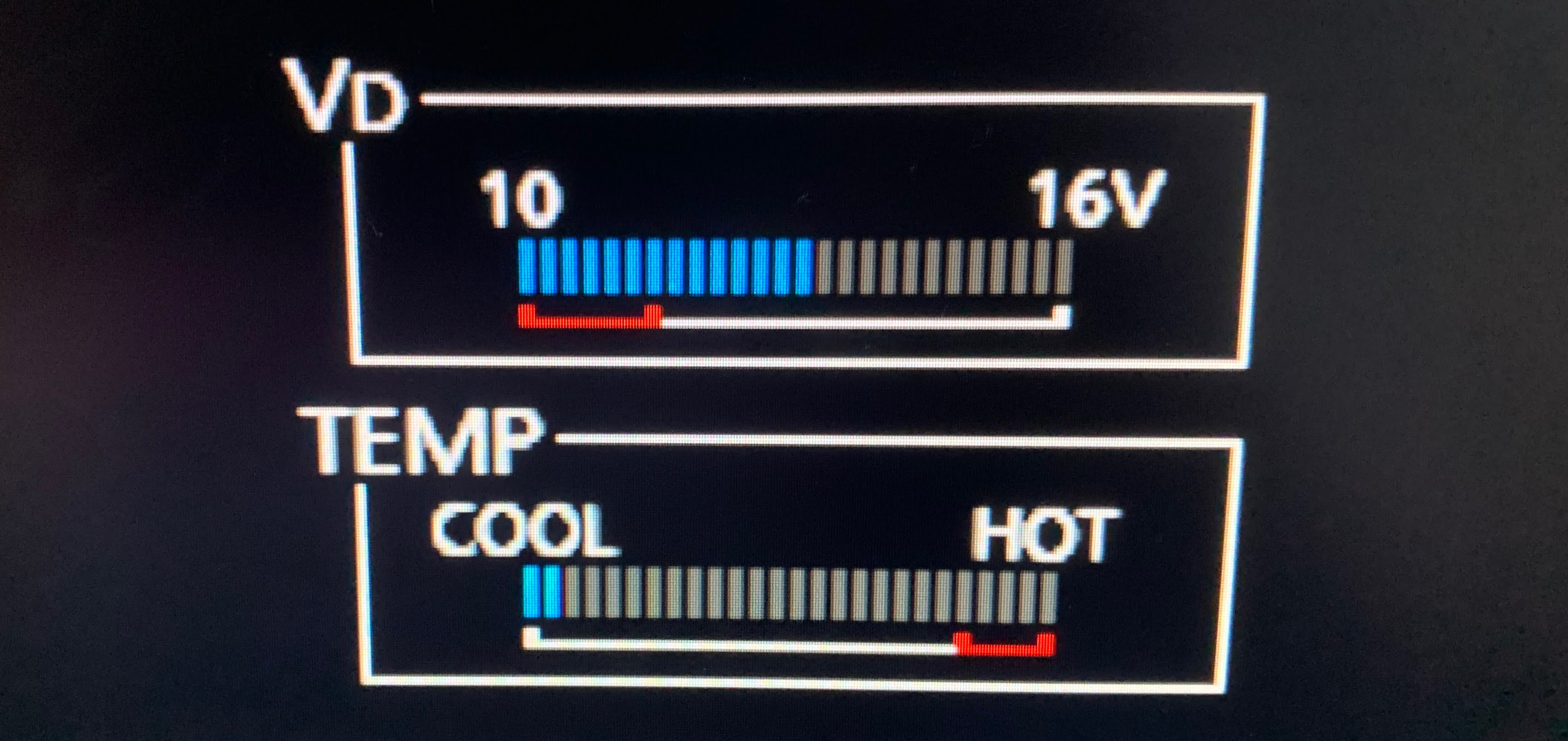
On the Icom touch screen, you can bring up a menu called meters. One of the meters is the Vd. This meter reads the real-time internal voltage of the 7610. On the scale, there is a red section and if the voltage gets to this point the radio will shut down. Once the sufficient voltage is supplied again the radio will cycle on again. Thus the issue I was having. When I was transmitting I was drawing much more current then bring in a poor connection (resistance) thus drawing more current. When you draw more current your voltage goes down and if it goes below what the Icom 7610 wants the radio shuts down. As soon as it shuts down more than enough voltage is available as very little current is being used and the radio cycles back on again.
On the Anderson power pole site, they do have a bulletin as to why a connection issue may exist. Some causes they mentioned were a poor crimp connection if you decided to solder the connection a poor solder job and if the solder flowed down onto the connection tabs this could be an issue as well. I have to be honest I have been using Anderson power poles for a long time and I have never had an issue.
I wanted to see if the Anderson power poles have in my case become an issue. My test was set up as follows. I wanted to have a steady constant load on the Icom 7610 and what better way than to transmit an FT8 tune signal, I choose to use 100 watts. I would connect the radio as it was during the contest and then send an FT8 carrier at 100 watts. Record the voltage drop on the Icom Vd meter. Then remove the Anderson power poles from the Rig runner. One is the power cord from the radio, the other from the power supply to the Rig runner. Run the same test and record the results. finally, remove the Anderson power poles from the cable from the Icom and connect it directly to the Astron SS-30-M power supply which has screw terminals. Then record the results.
Before I began I checked the terminal voltage on the Astron power supply and it was 13.8 volts DC. Also during the tests, the power supply voltage stayed at 13.8 volts DC. Below are the results from the tests.
Just a word about the Vd meter before we begin. I determined that the Vd meter scale is 0.24 volts per hatch mark. Therefore the minimum voltage red trip line on the Vd meter scale is the 6th hatch mark from left to right (11.44 volts) with the first hatch mark counted as zero.

The first test was with the radio connected to the Rig runner via the Aderson power pole and the power supply connected to the Rig runner via the Anderson power pole. The results below when FT8 test tune at 100 watts was Vd voltage dropped to two hatch marks above the trip red line.

For the second test, I removed the Rig runner and connected the two Anderson power poles one to the other. The FT8 100-watt test tune gave the same results, two hatch marks from the trip red line.

Finally, I removed the Anderson power pole from the radio power cord and stripped the ends and attached it directly to the Astron power supply via its screw connectors. The FT8 100 watts test resulted in a surprising result of 5 hatch marks above the red trip line.

Removing the Anderson power poles from the circuit seemed to give some impressive results and I am going to leave it this way. If I need to use the Rig runner power bar I can power it from a spare Astron 25 amp supply I have. Once I have some spare time I am going to take the pair of Anderson power pole connectors apart and see if I can find what did possibly wrong.
Continue the adventure.

Now that fall is just around the corner and summer vacations, lazy days in the sun and let's not forget the yard work comes to an end it makes more time for radio. Over the summer I have found the bands are a bit more on the quiet side, blog posts slow down and for the most part, we are preoccupied with summer.
For those of you who are into CW and the key has gathered some dust over the summer break a great way to slide back into the CW groove is to take part in some 1 hour "mini-contests"
The K1USN SST (Slow Speed Test)
The event runs twice a week Friday 2000-2100 UTC
Monday 0000-0100 UTC which is Sunday eve but Monday according to UTC time....always threw me off when I first got into contesting.....anyways...
This 1-hour mini contest max's out at 20 wpm and I have done many of these and sent at 16-18 WPM and had many contacts. If you are rusty and want to pick up the dit dah pace a bit this contest is a great place to be. If you are a veteran op it's a great place to slow the pace down and donate an hour.
The exchange is your call sign, name and your State or Province. The contest program N1MM+ supports this contest also if the call sign you are working on is in N1MM+ database the op's name and State/Provence is auto filled if you want. This way you can start by just having to copy the op's call sign.
ICWC MST (Medium Speed Contest)
Mondays 1300-1400 and 1900-2000
Tuesdays 0300-0400
In this 1 hour mini contest the CW speed picks up the pace a bit to 20-25 WPM BUT on request will slow down. This contest is also supported by N1MM+ but under the UDC section (user-defined contest) I'm not going into the UDC format here but use the ICWC link above and they provide a link to the N1MM site to set this contest up. The exchange in this one is your call sign, name and QSO number (serial number as it's called)
This event runs 4 times a week. Wednesdays 1300-1400 UTC and 1900-2000 UTC
Thursdays 0300-0400 UTC and 0700-0800 UTC
In this 1-hour mini contest, one has to put their seat belt on and realize your hair (if you still have any) will be blowing in the wind with the CW speeds. This contest is looked at as a high-speed mini-contest. The speed starts at 25 wpm and goes up from there. When I say up.... speeds into the 40's wpm....mind-boggling. Anyway, N1MM+ does support this contest. In my humble opinion if you are in the 20ish wpm range give this contest a listen only. Search and pounce just listening to the calls and see what you can pick out. The average speed is mid 20's to mid 30's wpm. The exchange your call, name and CWops member number or if not a member your State or Province.
I do take part in this contest but I am not as yet a member of the CWops so my exchange is NB for New Brunswick. Membership details can be found at the site from the link above.
So there you have it if you are interested this fall and winter and have some time on your hands give the 1-hour mini tests a go. Here is the way I look at it....I busted my hump learning CW (it was not an option when I went for my ticket) and I just did not want to throw that away. I had done what most did to get my ticket I learned the code just to get past the exam and I planned to forget about it.
I did leave the code and radio alone as I had a young family like most of you did. I then started to have time on my hands and the love for radio was alive again. I listened to CW and to be honest I was a few code letters short of a full load if you know what I mean. Slowly started to pick it up again and have never looked back.
-------------------
------------------
---------------------
--------------------
Above is me stepping down off my soapbox....I hope you found some useful information from the above.


