Author Archive
 A year in review…….
So how was 2011 here at VE3WDM,
I have always been a QRP operator but for the first time I decided to drop my output power to less than 5 watts. By the end of 2011 the output had dropped to 500mW's or less with great success as well.
I took some time to look around the shack to notice how much "stuff" I had that was just taking up space. I then put up for sale items I was not using and made enough for some new toys.
I discovered WSPR and all that you can do with it.
I was able to upgrade the shack. The Elecraft K3 was upgraded with a second receiver and matching filters. Along with some added treats.
My main contest antenna was the Sidekick from High Sierra antennas. It was a great antenna that gave me coverage from 10m to 80m. The problem was it could only be outdoors when I was on the radio due to antenna restrictions. I tried the Sidekick in the attic along with my 20m dipole but it just did not work.
I sold the Sidekick and ordered the Alpha Delta DX-33 and installed it in the attic. I am now able to work 10m to 40m anytime I want and not worry about an outdoor antenna.
I found time to get some kits done and added to the shack.
I also had some Plasma TV interference so I purchased an MFJ-1026 and that fixed the problem it's a great unit.
I did more portable op's this year with my Elecraft KX1 and had a great time.
There was my trip of a life time to the UK and ham radio came along for the ride as well.
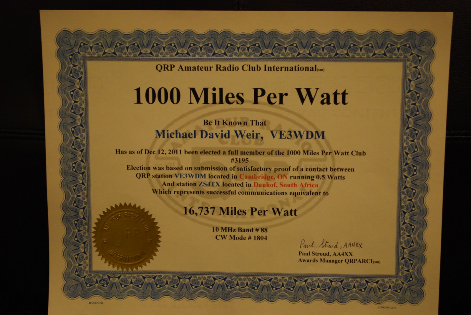
There was some wall paper added WAS awards, 1,000 miles per watt at 8,325 miles per watt. I then topped that record with 16,737 miles per watt.
Much more went on but these were the highlights here at VE3WDM!
I have always been a QRP operator but for the first time I decided to drop my output power to less than 5 watts. By the end of 2011 the output had dropped to 500mW's or less with great success as well.
I took some time to look around the shack to notice how much "stuff" I had that was just taking up space. I then put up for sale items I was not using and made enough for some new toys.
I discovered WSPR and all that you can do with it.
I was able to upgrade the shack. The Elecraft K3 was upgraded with a second receiver and matching filters. Along with some added treats.
My main contest antenna was the Sidekick from High Sierra antennas. It was a great antenna that gave me coverage from 10m to 80m. The problem was it could only be outdoors when I was on the radio due to antenna restrictions. I tried the Sidekick in the attic along with my 20m dipole but it just did not work.
I sold the Sidekick and ordered the Alpha Delta DX-33 and installed it in the attic. I am now able to work 10m to 40m anytime I want and not worry about an outdoor antenna.
I found time to get some kits done and added to the shack.
I also had some Plasma TV interference so I purchased an MFJ-1026 and that fixed the problem it's a great unit.
I did more portable op's this year with my Elecraft KX1 and had a great time.
There was my trip of a life time to the UK and ham radio came along for the ride as well.
There was some wall paper added WAS awards, 1,000 miles per watt at 8,325 miles per watt. I then topped that record with 16,737 miles per watt.
Much more went on but these were the highlights here at VE3WDM!

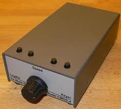
Idiom Press CMOS-4 Keyer………
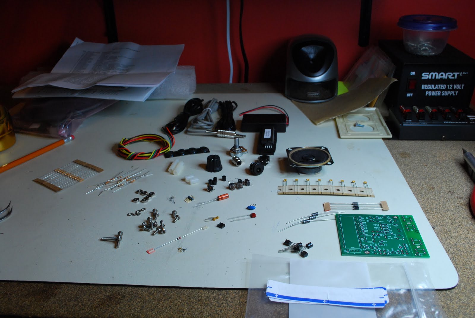 |
| Sorting the parts |
house one day. Anyway, I had read many great reviews about this keyer and has seen some YouTube demonstrations of it was well so I was eager to get it built and running. If you have read in
 |
| RCA troubles |
my blog in the past the first thing I like to do with any kit I get is do the inventory of parts. It lets me know all is here as well familiarizes me with the parts. This kit like all the others had part numbers for the parts but for some reason the list gave you a part number and told you it was a 15 ohm resistor for instance and that there were 20 of them and that was it!! So these 15 resistors were they R1, R20, R3 or what, as the kit had other resistors with other part numbers and values assigned to them. So for all the parts I had to go through the build
 |
| Resistor and diode layout |
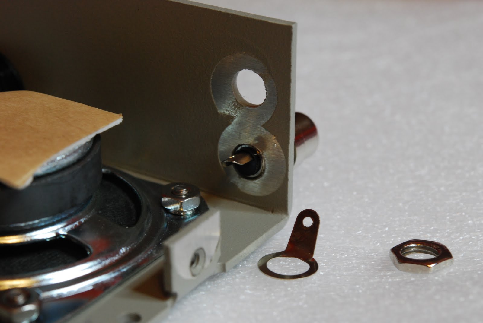
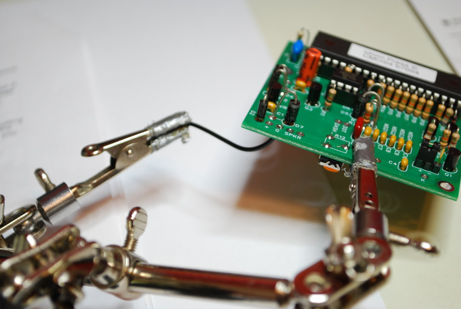
instructions and identify that transistor part number ZC4005 which was a MPSA92 transistor was in fact Q1 in the assembly instructions. Each part had to have this done and I then put the parts in a bag and labeled the bag with the assembly part number on it. The assembly instructions were very clear but more pictures would be very helpful during the build. Steps that involved an odd detail were marked out very clearly and at times in BOLD print. One part issue during the build was an RCA jack that would not fit through the per-drilled hole. This is not a disaster but a bit of a pain having to get the cordless drill out to open up the hole. The only other issue I ran into and should be rectified in my humble opinion is.....there are some diodes that have to be installed and there is a polarity to follow. To make this easier the
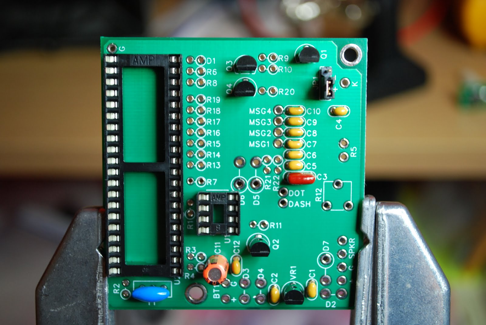 |
| Diode circles missing at bottom |
silk screen on the PC board has a large circle place over one of the diode holes. This is to help with placing the diode on the PC board with the right polarity. Well for some reason there are 3 areas D2,D3 and D4 were the circle did not make it onto the PC board. You are told of this in the instructions and shown on a layout diagram with the proper polarity. How about fixing the boards as well.........Those were the only issues I had with the build. The kit tested great once it was done and if you do order the CMOS-4 as a kit or already built make sure you read the operating manual cover to cover. This is were the kit really shines great detail has been put into the manual. Because this keyer is a real stand alone keyer all programing is done with your key no computer is needed. In the manual you are given exercises to do and make sure you do them!!! This will get you accustomed how the keyer works and how to program it as well. If you are in the market for a keyer this is one to take a close look at. In this post I wanted to include some assembly pictures as I found on the internet there were very few. As you are going through the build a picture would really help at times.
 |
| DC power jack very close to speaker |
 |
| Adding wires to board |
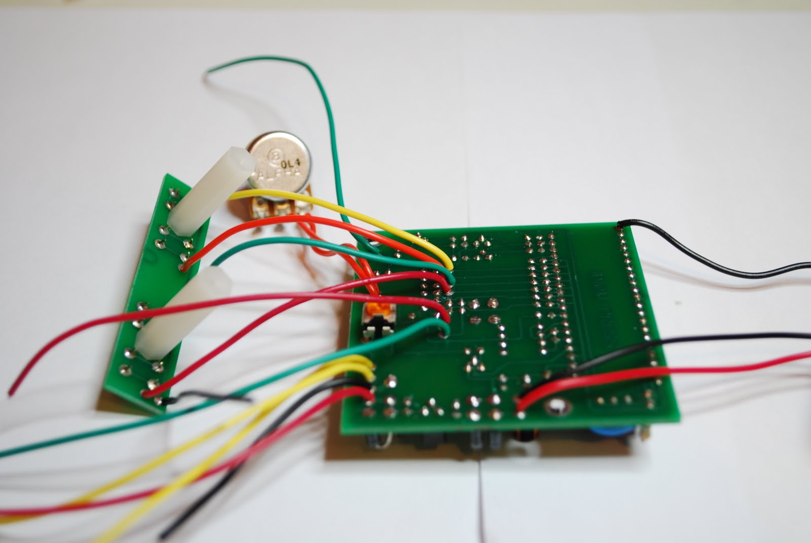 |
| All wires added |
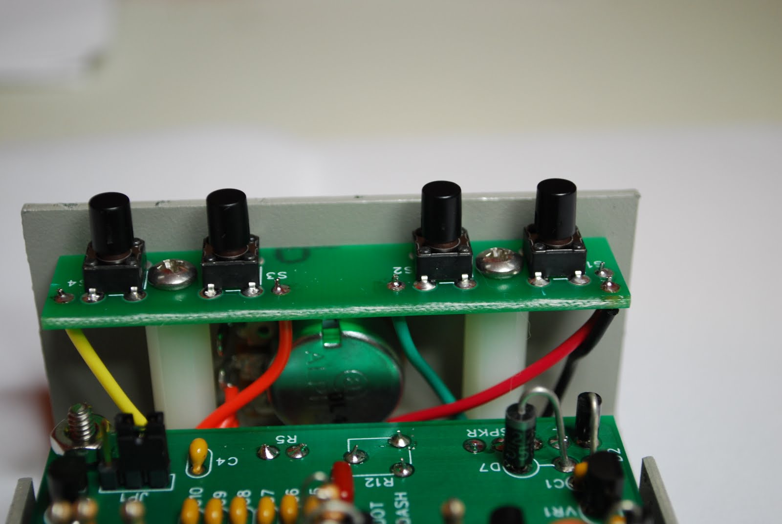 |
| Push button setup |
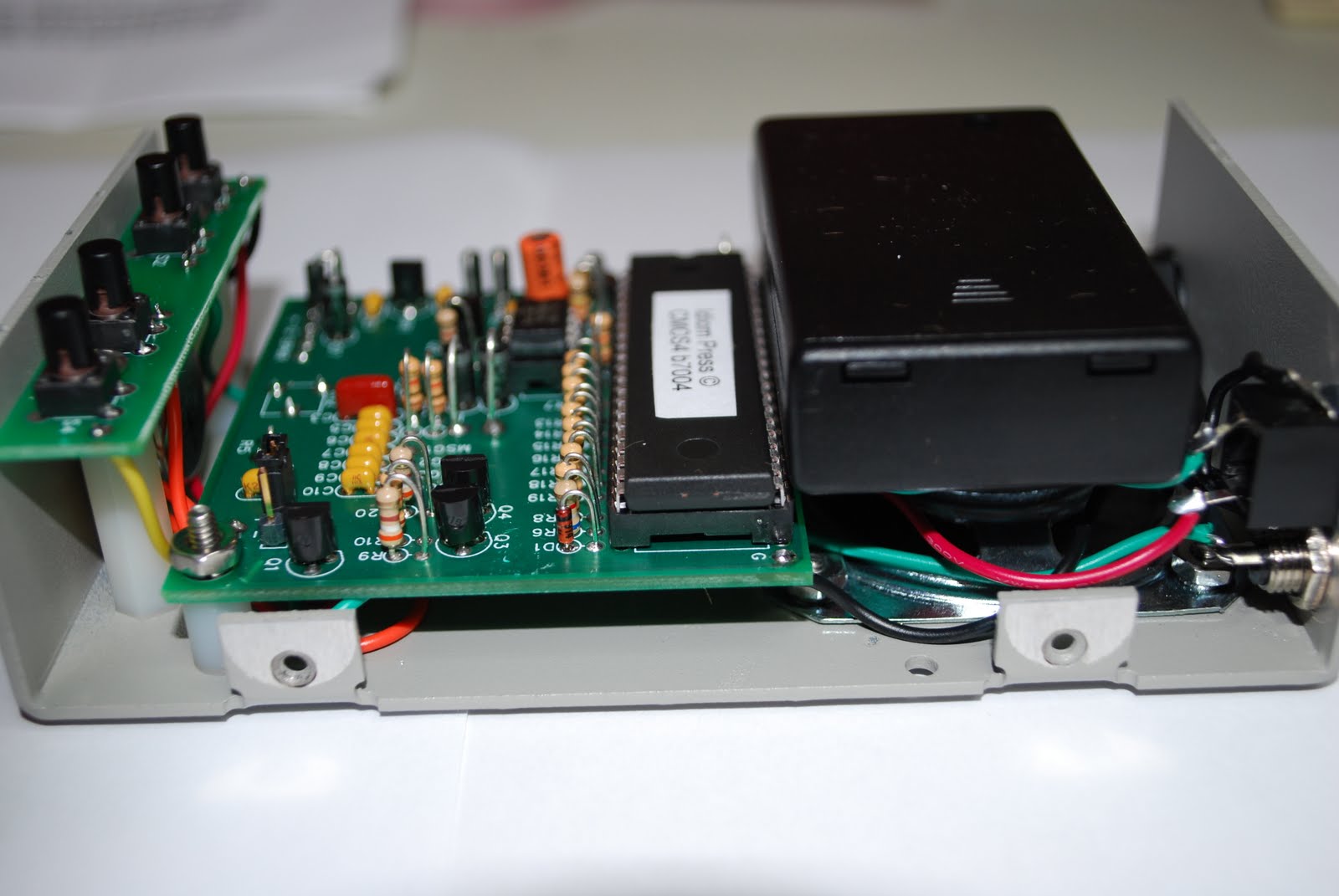 |
| Battery pack added |
Merry Christmas and best wishes to all!


Myself , Julie and Oliver wish you all a very Merry Christmas and a Happy New Year!!
New 1000 mile per watt record………
 |
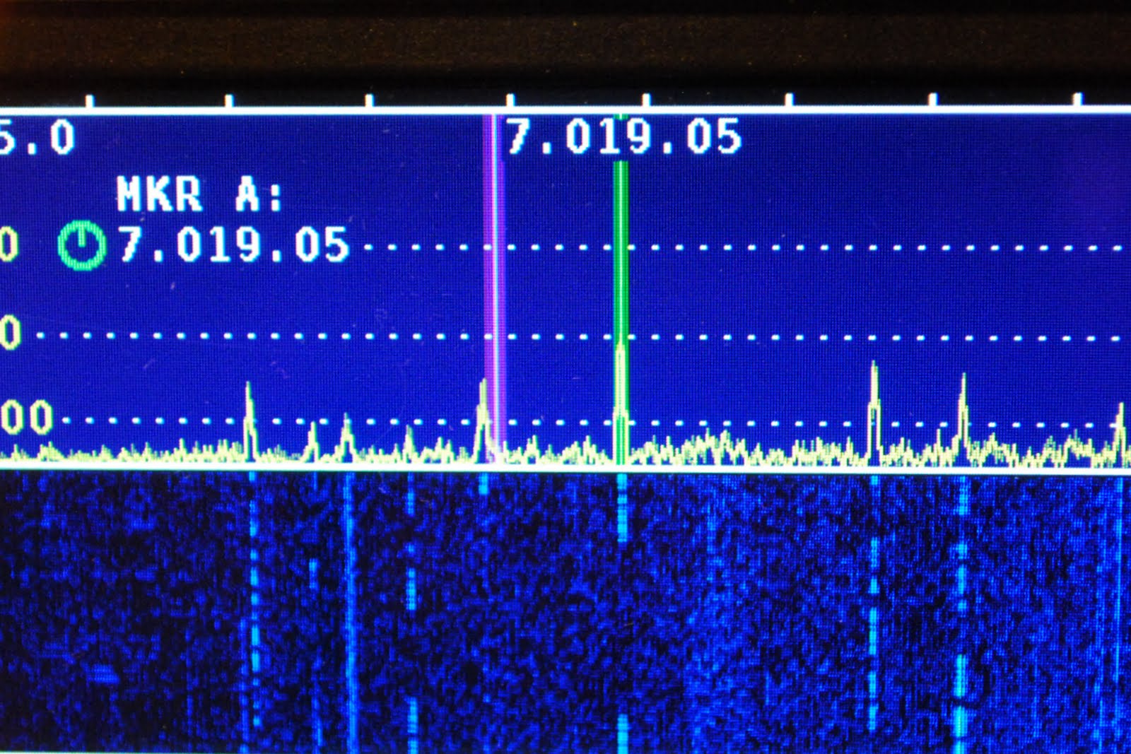
| The excitement had me fill in the wrong band a new one is coming for 14 MHZ (click for full size) |
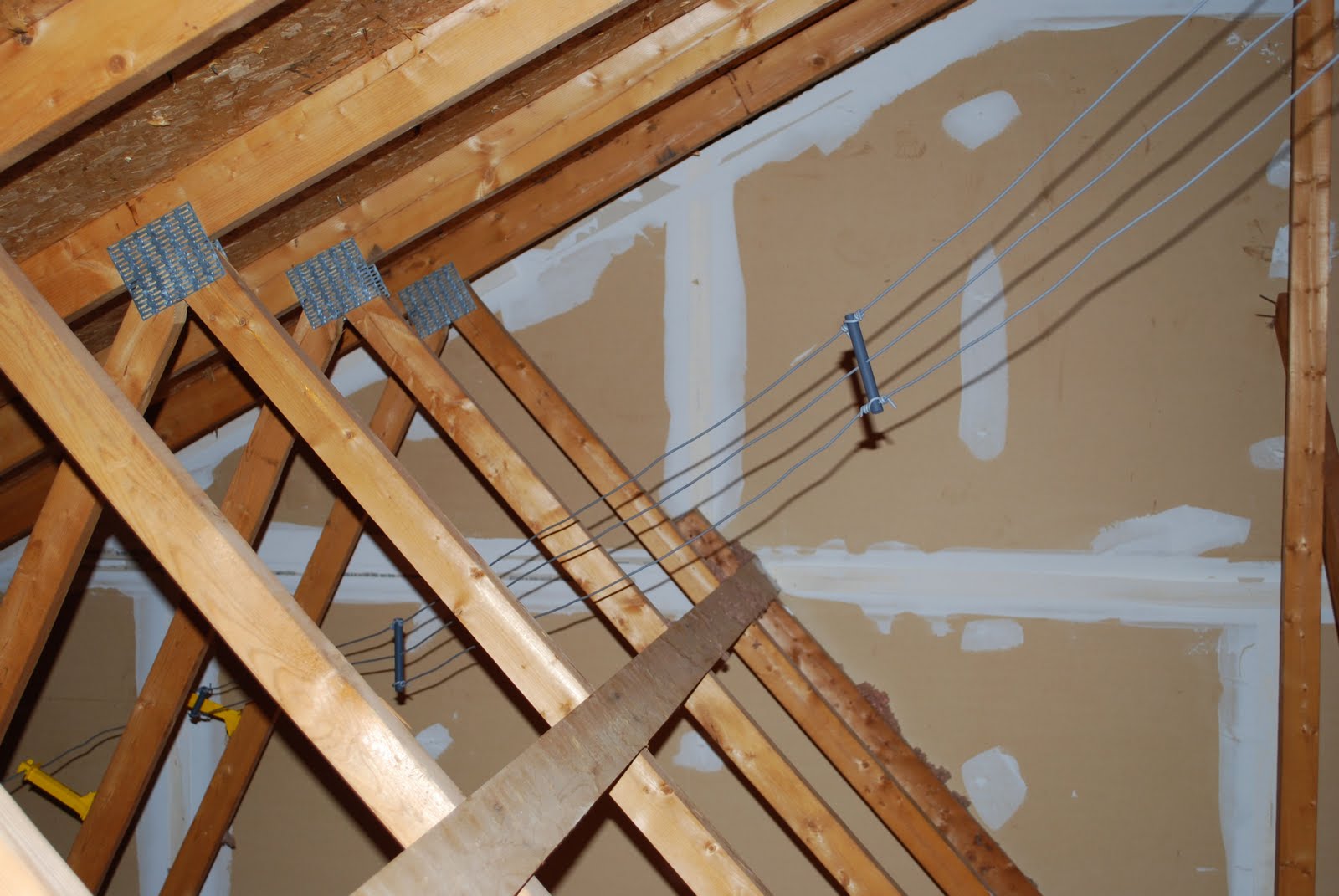 |
| Attic dipole (click to enlarge) |
my miles per watt all time high was 8325 miles per watt!! Now you also have to remember I am not running a huge tower loaded with eye candy beams. My radio waves into ham land are done with an attic dipole in a "Z" configuration (Alpha Delta DX-EE), so it has a nice wooden roof above an insulated ceiling below. Yes it is not the latest and greatest of antennas but I'm not doing to bad with it. During the contest I dropped the Elecraft K3's power to 500mW's to see what I could do. To my surprise ZS4TX came back to me... I made contact and exchanged contest info. After the contest I emailed ZS4TX (Bernie) and he was shocked that I was running QRPp at 500mW's. My signal according to Bernie was above average into South Africa. So my new "to beat record" is 16,737 miles per watt I more than doubled my last record!!!
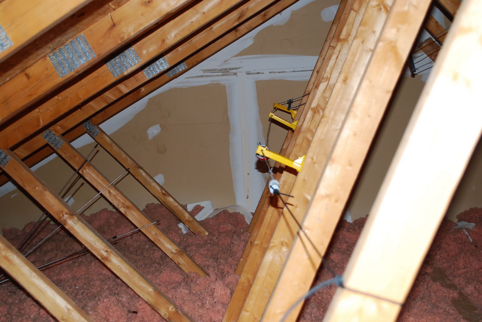 |
| The folded or "Z" part (click to enlarge) |
The Ubuntu Linux learning curve………..

trying what they said then getting back to the Youtube video and then back to the same spot in Ubuntu again. That was just a receipe for frustration as this game plan was far from smooth going. It was off to some user groups but that turned out most of the time to be a hunting trip. I would end up going to so many links that the original question was forgotten and at my age that process does not take long. I came to the conclusion the written word in the form of books was the way to go to solve this monkey on my back. I hope to become more familiar with the Ubuntu OS now and get past the wall I have come up against. Over the Christmas break I will be taking a leisurely approach with the help of some books and hands on learning to get Ubuntu in check.
The Elecraft P3 has arrived……
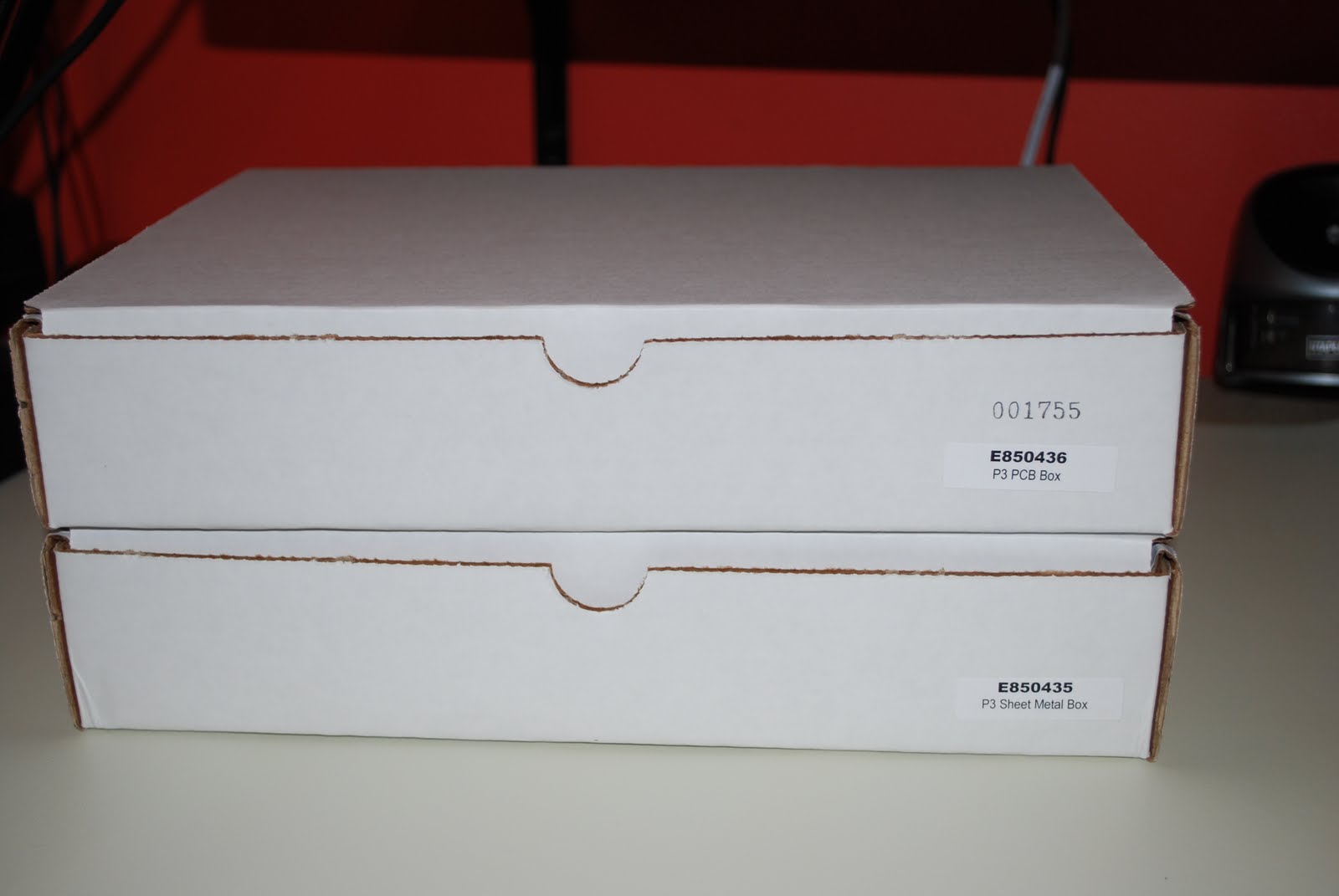 |
| The shipment arrived |
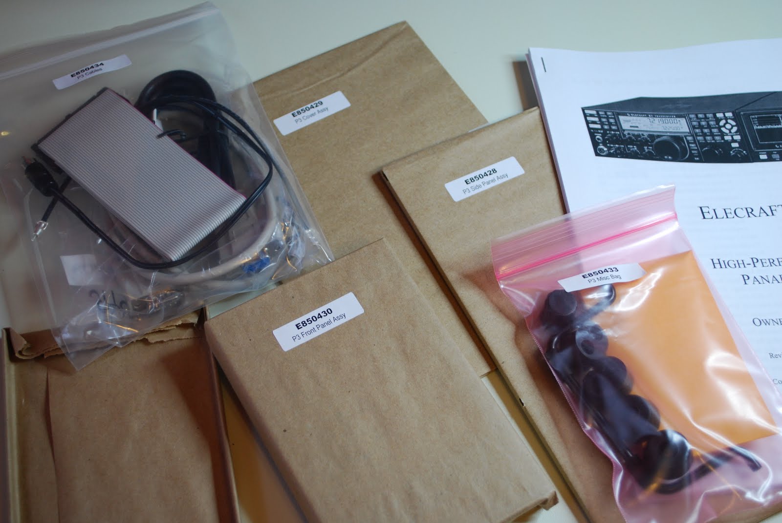 |
| Ready to go |
surrounded in bubble wrap. I sat down Saturday afternoon as the morning was dedicated to putting up the Christmas tree and decorating our home. As always I took inventory of all the parts I encourage anyone who orders any kit to make sure you do the inventory. This kit is another of Elecraft's solder-less kits. It comes with the boards (front panel board with LCD, rear I/O board and rear RF panel
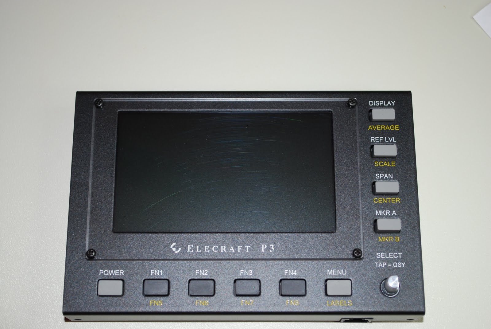 |
| Front panel done |
 |
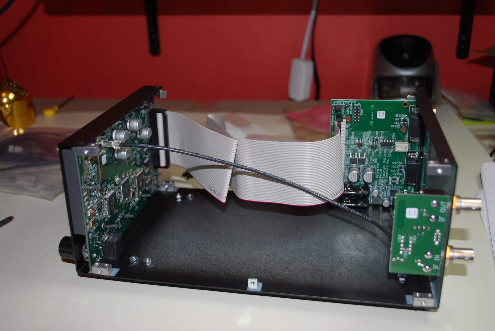
| I/O board installed |
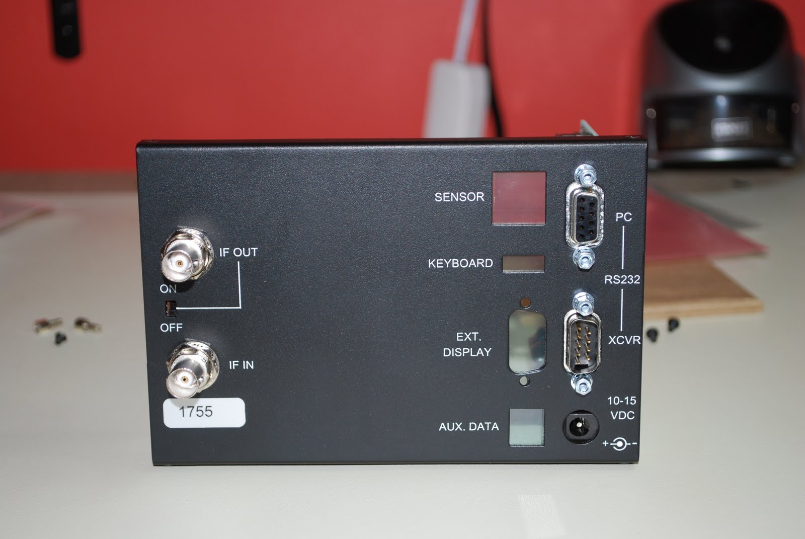 |
| Back panel |
 |
| The finished product |
 |
| Hooked up to K3 |


