Author Archive
 GAS is Rearing its Ugly Head
GAS - Gear Aquisition Syndrome
I have some excellent radios. I have a KX3 that does everything including ironing my pants (well almost) and a Ten-Tec Eagle that has the smoothest CW anyone could ever want. I also have old crumugeonly radios that require the patience of Job to operate. I've been well pleased with my collection of RF generating and receiving gear for quite a while. However, my Eagle is showing its age. I had to recently replace its T/R relay and the encoders need some cleaning, but it still sounds beautiful.
The problem is these newfangled rigs with their dang, pretty front panels providing information overload with aluring displays of 3D waterfalls and teleporter controls (maybe I mis-read that last one in the specs). Many of my QSOs now are with operators that have shiny new rigs. It's just not fair that I'm staring at a segmented LCD display... or in the case of my GRC/9, the front panel equivalent of a Slide Ruler.
 |
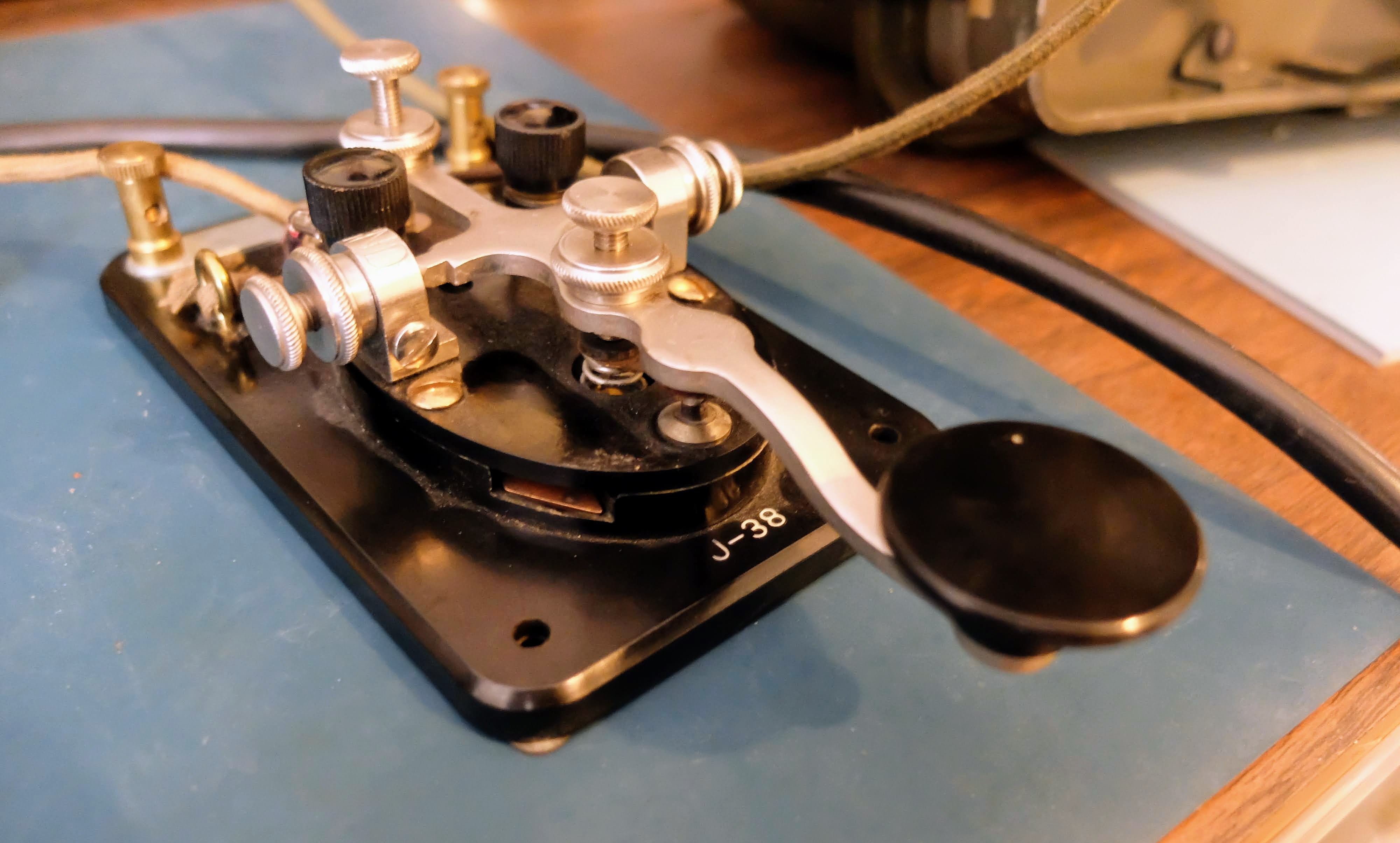
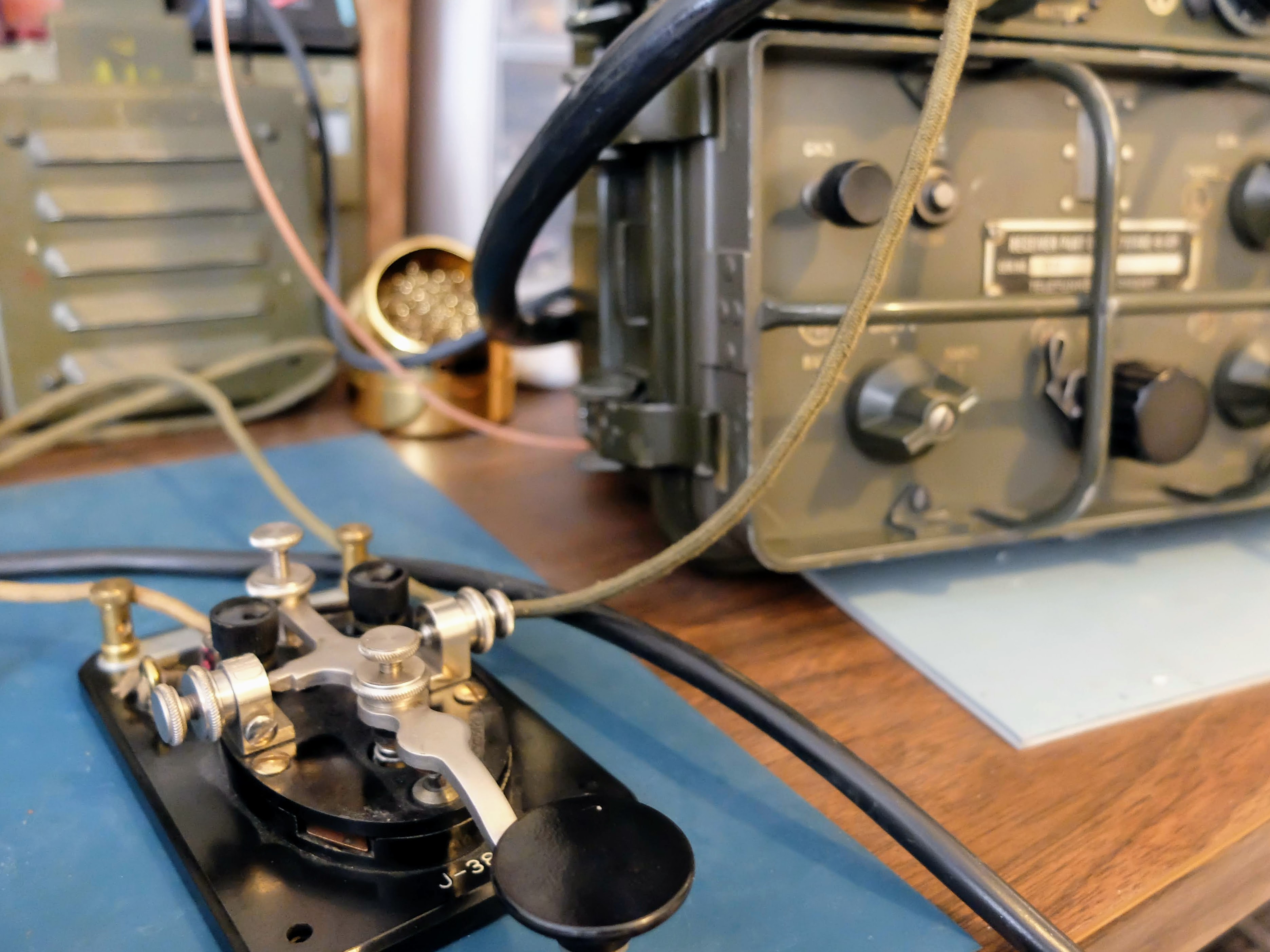
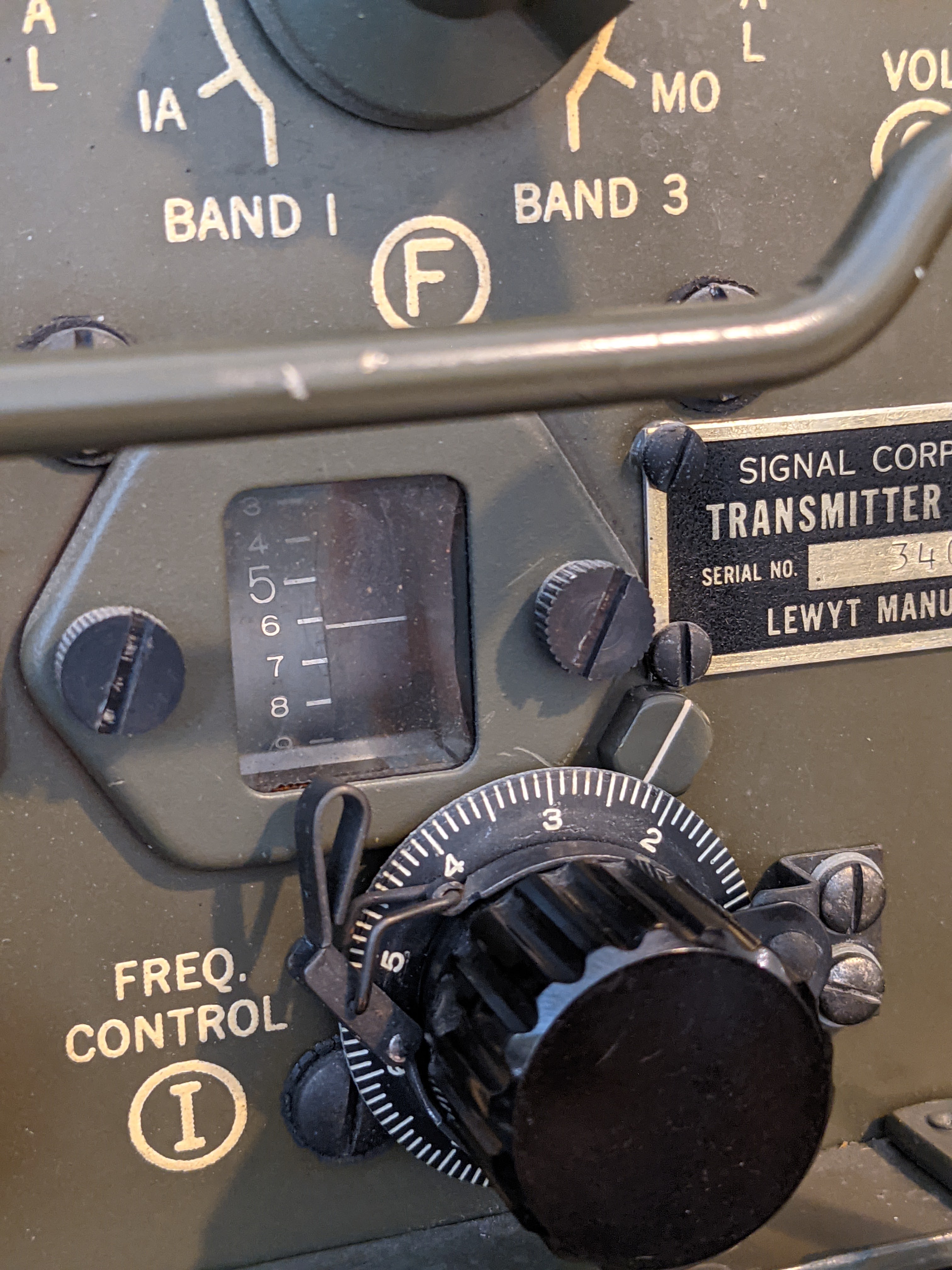
| The GRC/9 has the operating interface of a Slide Ruler but wow it's fun to operate... slowly and noisily |
 |
| The KX3 interfaces wonderfully to my Computer but it looks dated |
Surely ham life must be better when I can gaze at the equivalent of a smart phone on the front panel when using the oldest operating mode known to man?
The Genesis of "Want More"...
In preparation for the upcoming camping season in our RV, I wired a spare 12v 25A circuit in the camper's inverter to bring 12v rig power to the dining table, and co-opted the 75ohm cable running to the cable TV output outside the camper for watching TV (why would anyone watch TV outside the camper). That cable TV output now takes my antenna connection out of the camper without drilling any holes. I bought a stellar thing called a "flagpole buddy" to hold my 30 foot telescoping mast on the ladder and wallah, I have a portable Ham shack. I was using my Ten-Tec Eagle on the dining table, and my wife was not-enthused with having half of the dining table consumed by my bleeping radio. I assured her I'd set it on the seat when not in operation, but I still received "the look".
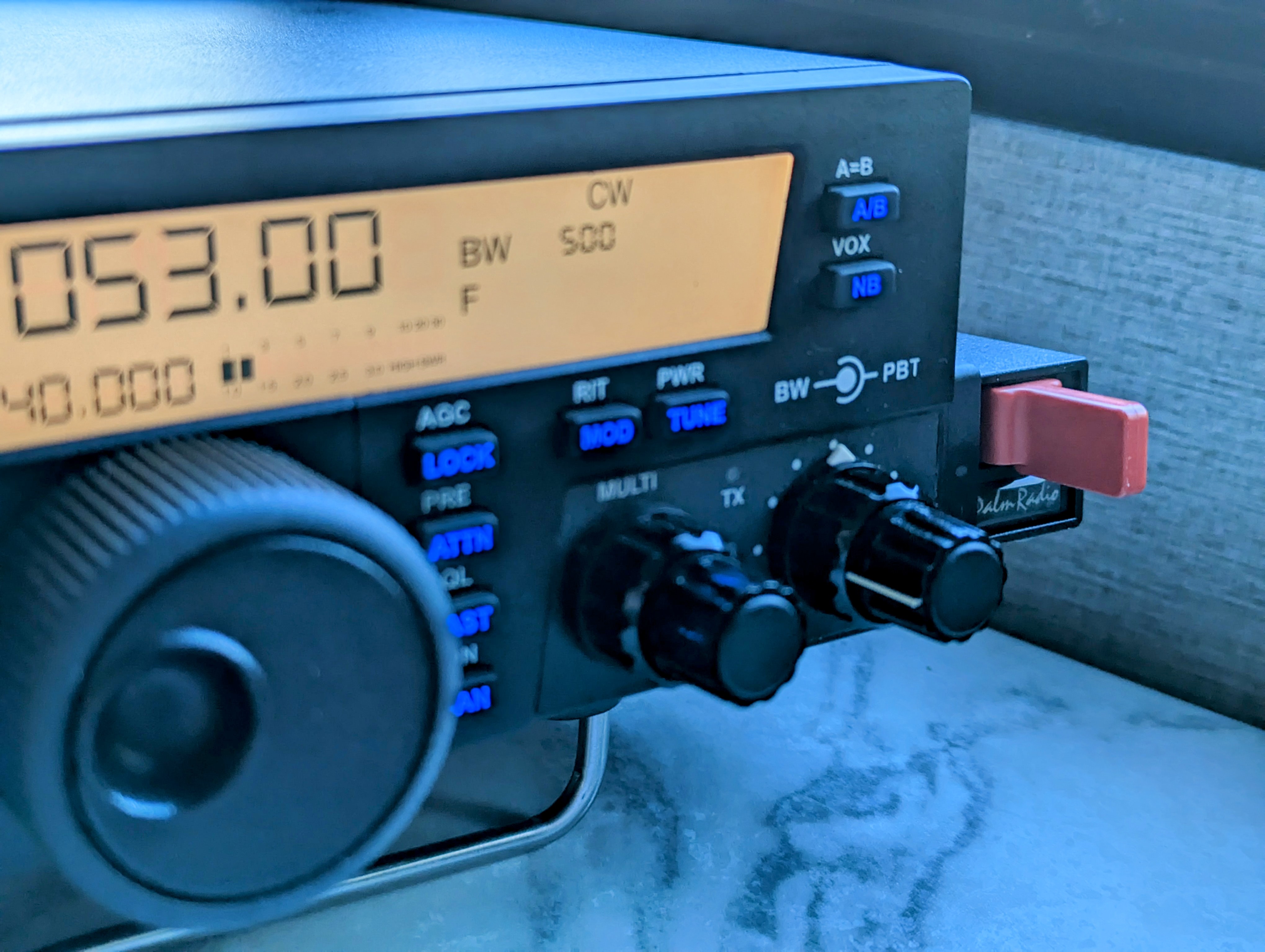 |
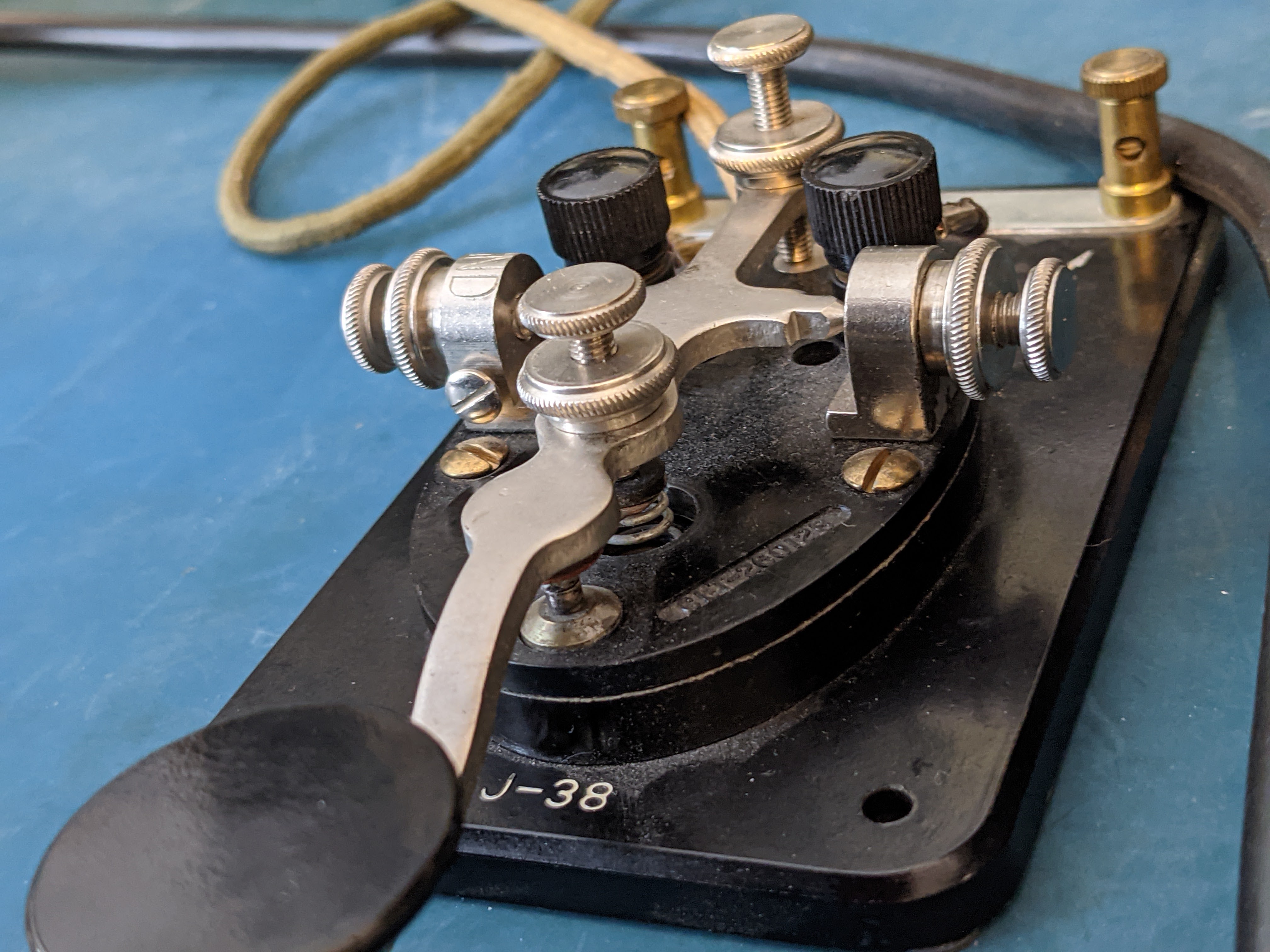
| The magnetic in the Palm Radio Paddle attaches to the side of the Eagle when operating portable |
 |
| Flagpole buddy holds the mast extending up to 35 feet |
My KX3 would take up less space than the Eagle but it's a pricey little thing to leave in the camper, and I primarily use it now as my primary station in my home shack now because it's wired up to the computer using HDSDR to provide a panadapter display.
I convinced myself that the KX3 should stay in the Shack. Sometimes I do raise my power beyond QRP if the other station is struggling to copy me and as I'd be operting from a compromised antenna I wanted a rig capable of QRO, when necessary.
So being the wise and kind husband that I am; I started looking for a small, portable, inexpensive radio capable of QRO. All this was to please my wife of course.
I used to own a Yaesu FT-857 that I kept in my truck, but it was terrible at CW (IMO) and that rig seems to be pretty rare now... After considerable searching I settled on a Yaesu FT-891. They had good reports and I could separate the face and it would take up very little room on the table. Plus it had a band-scope of sorts (ah shiny). But alas, I couldn't find used ones that didn't look like they'd lived under the seat of an off-road vehicle racing in the Baja, and the new ones are out of stock everywhere. All that web searching kept popping up the rigs with the pretty front panels. Google decided it needed to serve me advertisements of pretty radios everytime I opened any web site.
GAS
Reality Strikes
The Endurance of CW in Amateur Radio
CW Spans a Century

 |
| Radio Telegrapher School for Enlisted Specialists 1921 |
What other modes have remained as popular standards using standard ham equipment and continuously in use by amateur radio operators as CW?
Modernizing the DY-88 Power Supply
Go with a Modern Vibe

Turning low voltage to high voltage
Bad Vibrations
Solid State

Note
. . . The pins are numbered 1 to 7, pin 1 is the large diameter pin on the right, and pins are counted clockwise from that pin. . . .
Results

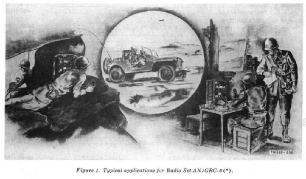
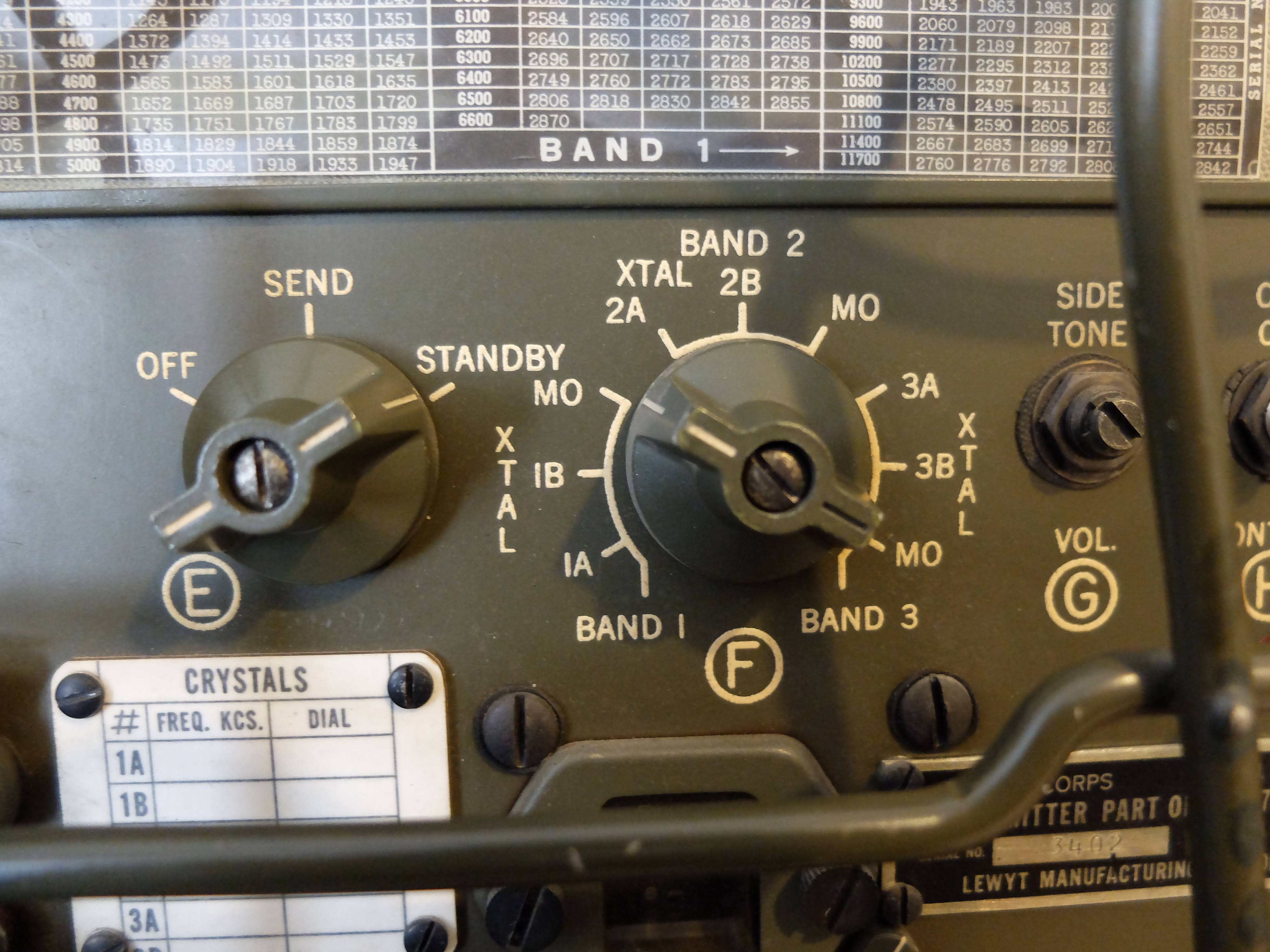
AN/GRC-9 aka “Angry Nine”
AN/GRC-9 - Long lived military comms
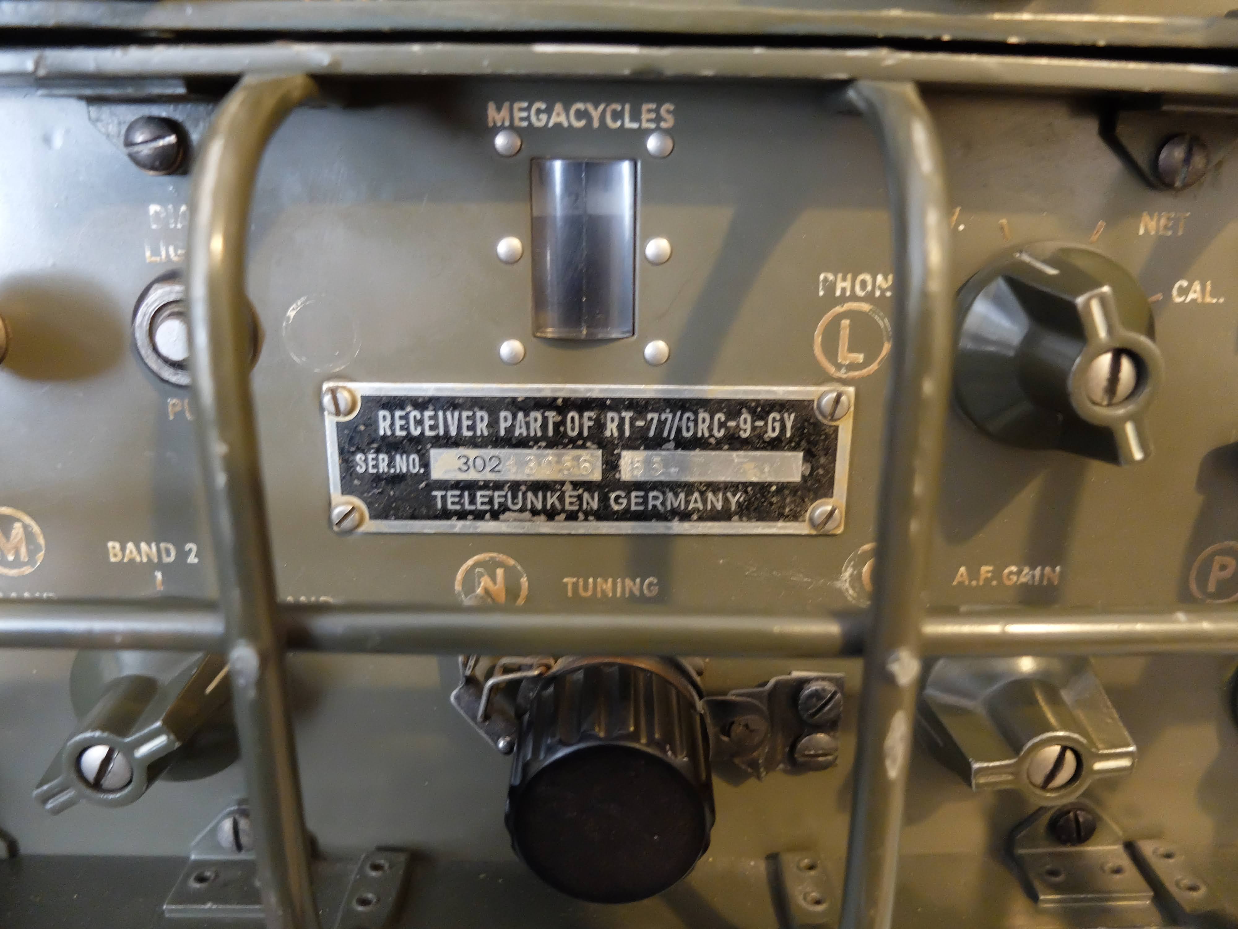
 |
| My lovely (and radioactive) RT/77-GRC/9 |
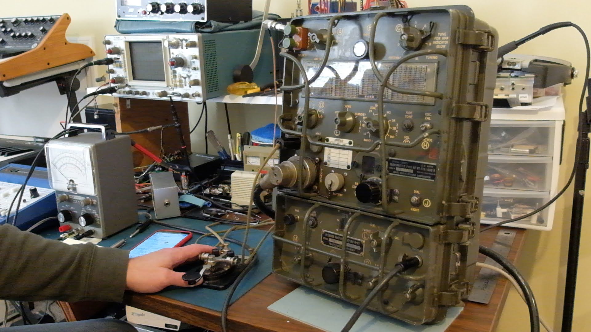
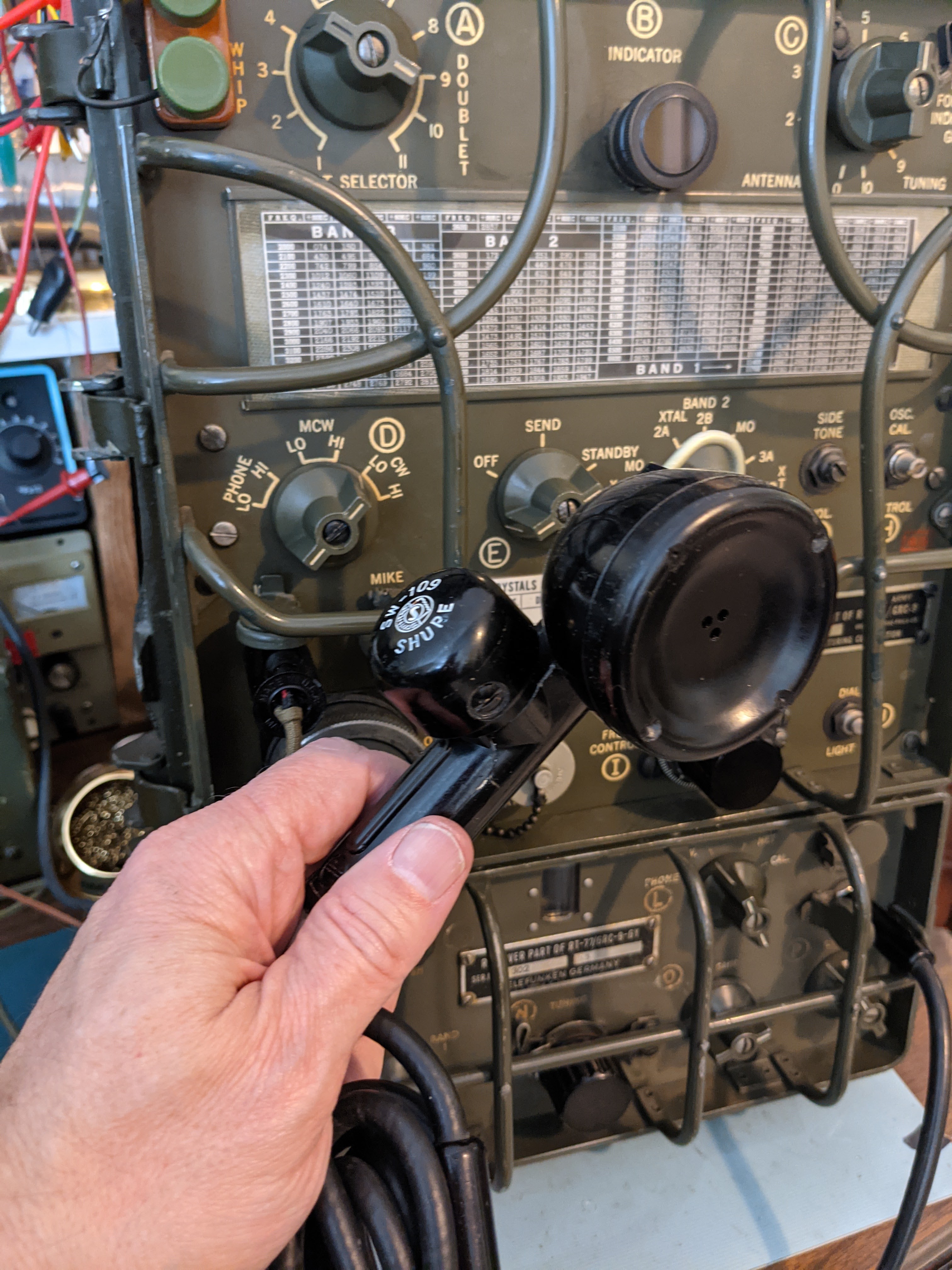
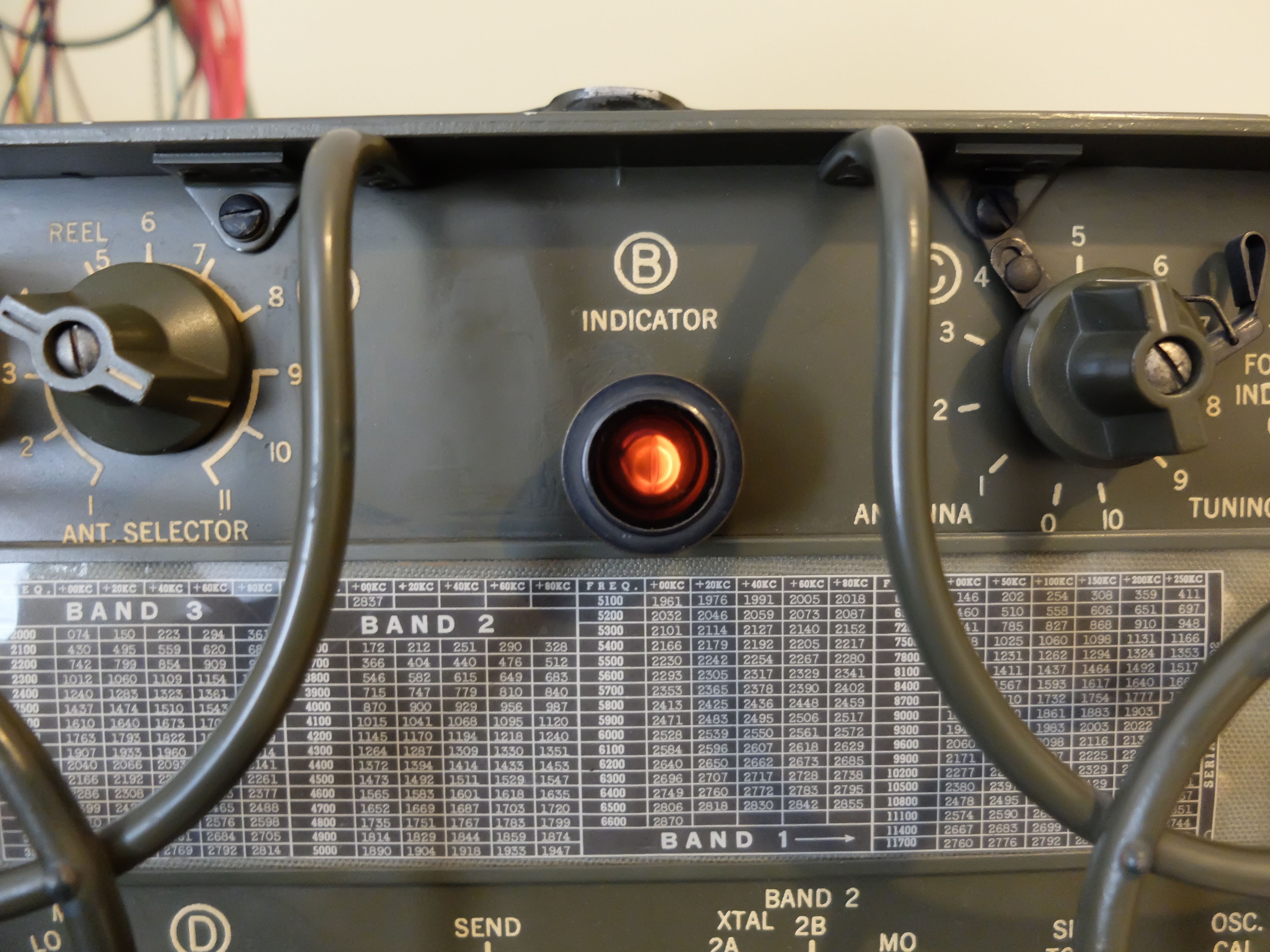
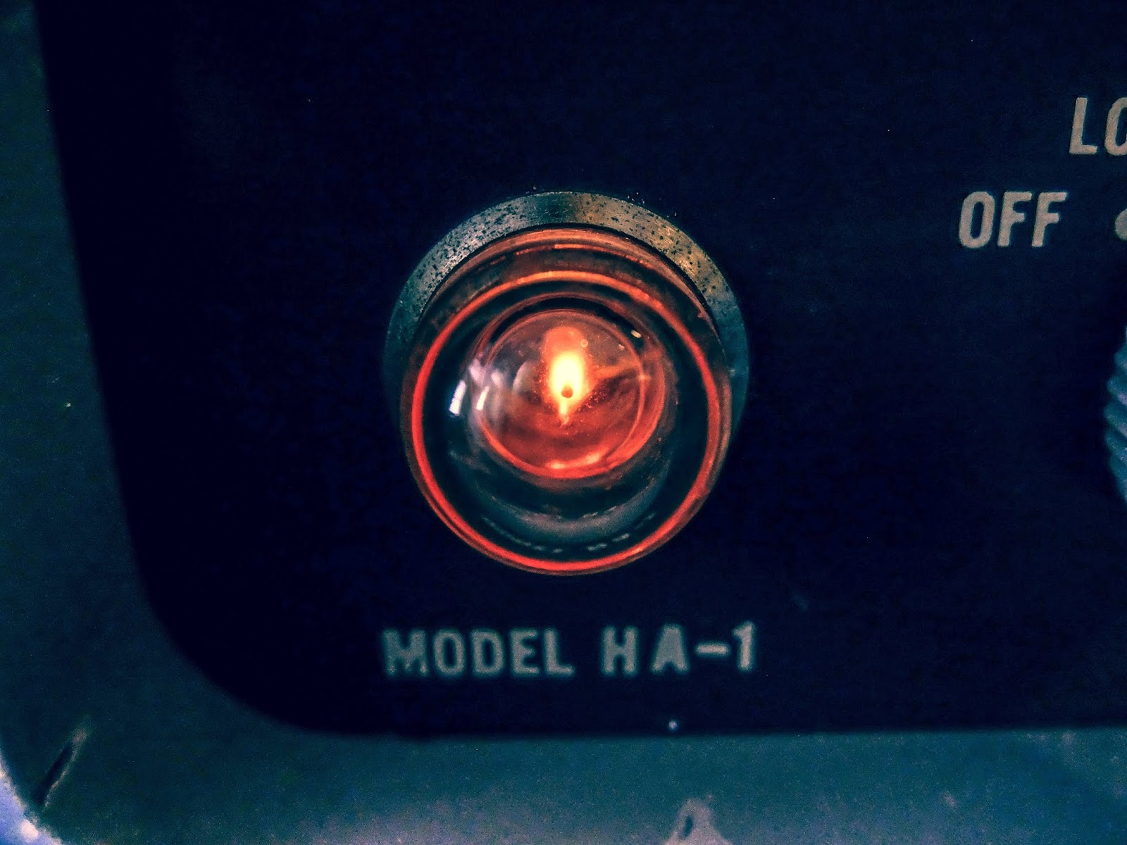
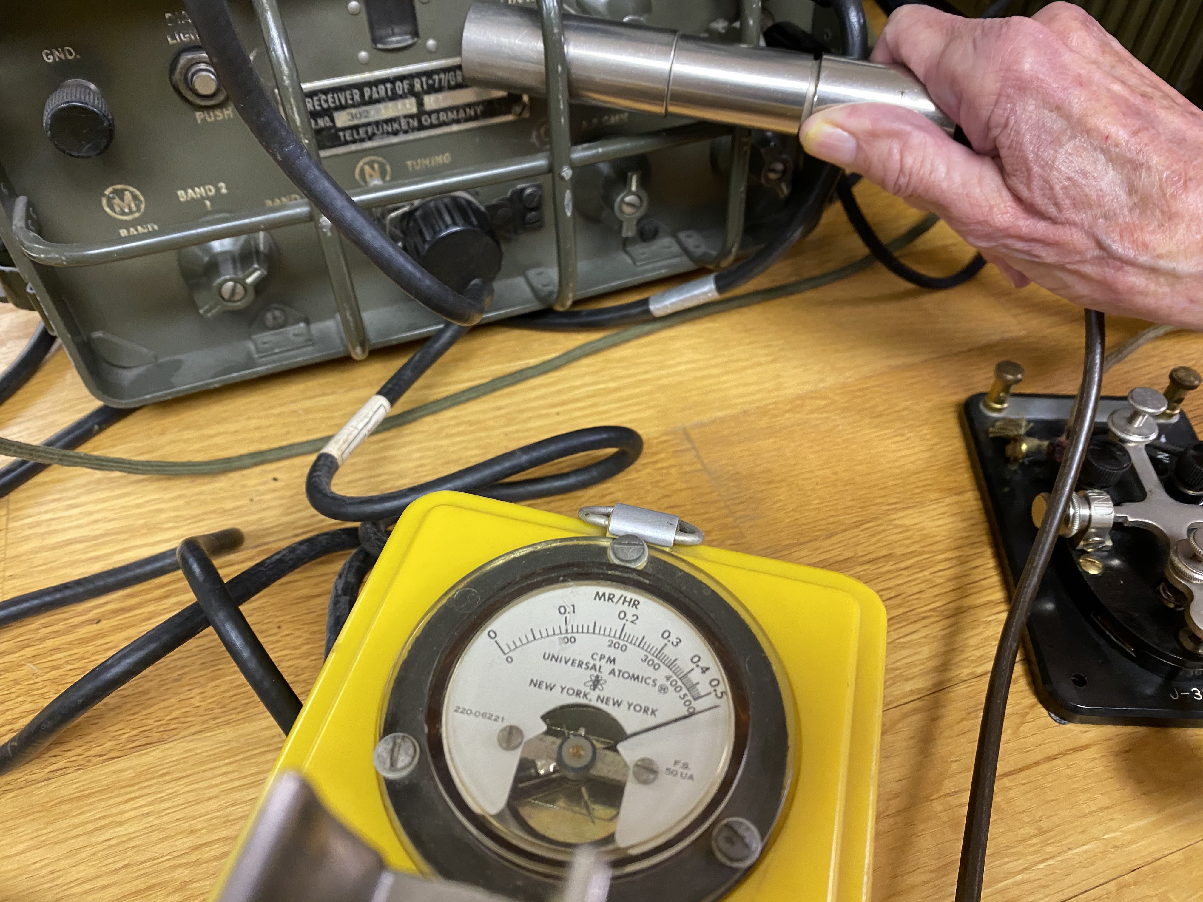 |
| Hot receiver, in more ways than one |
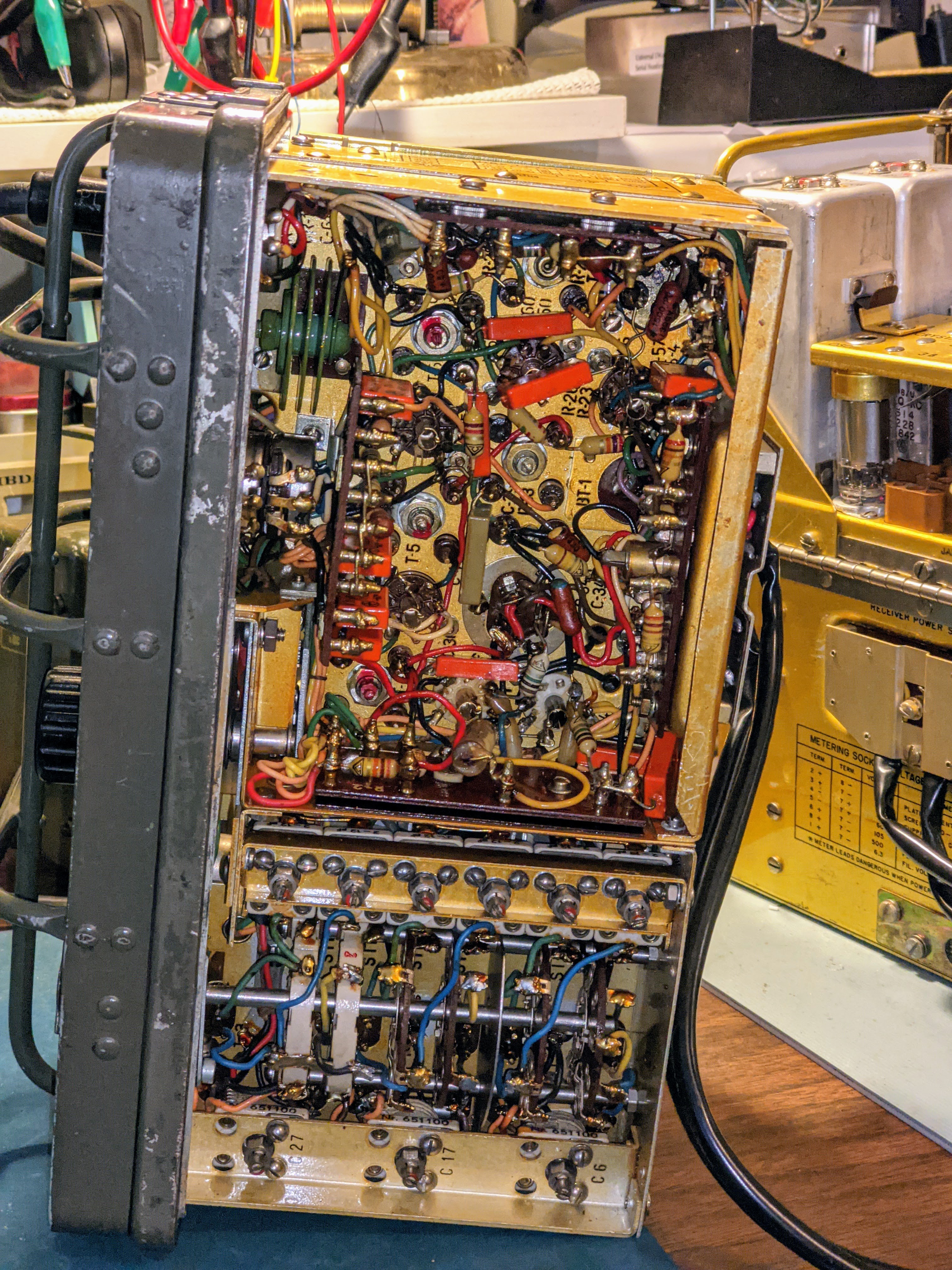
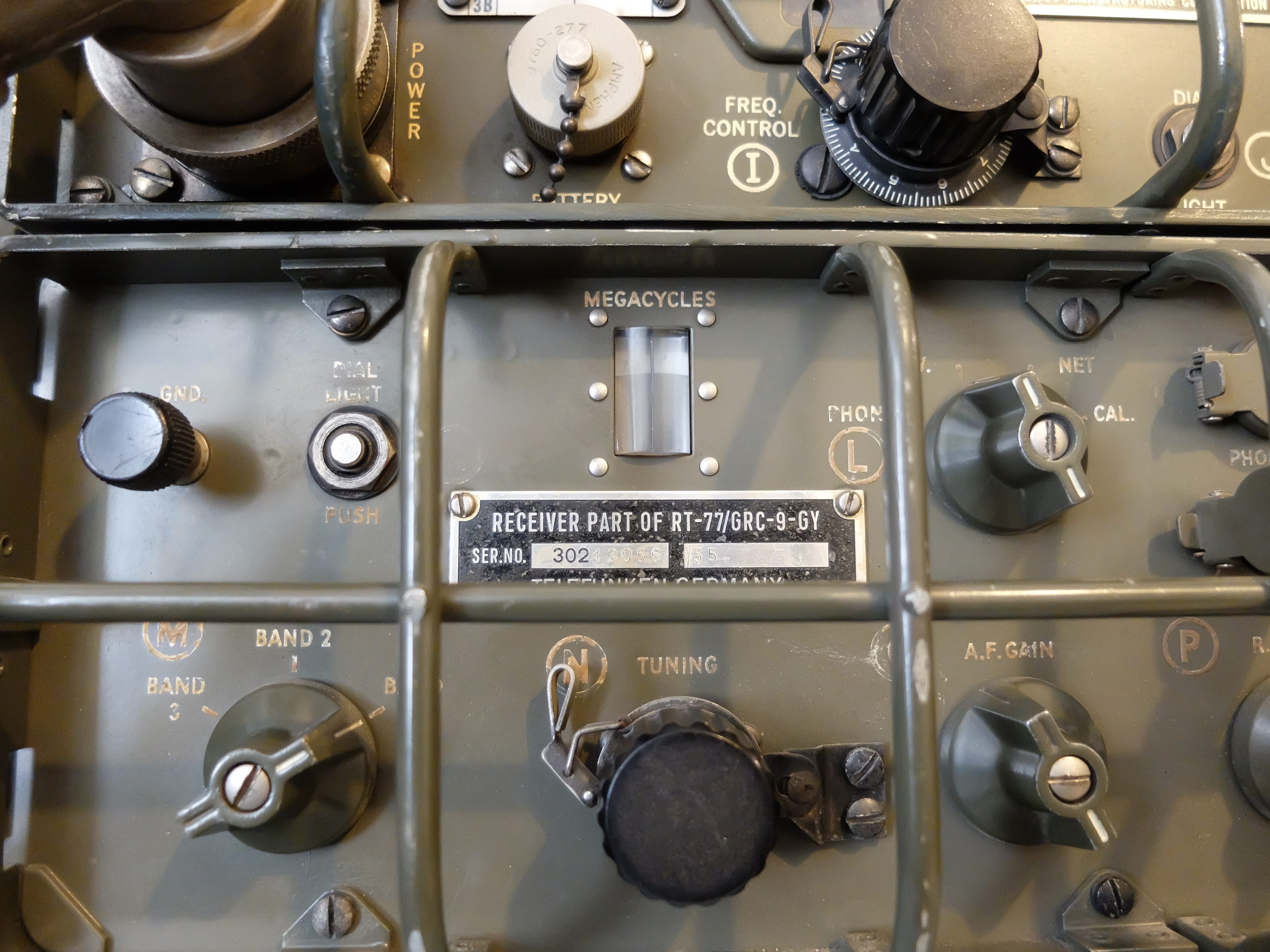
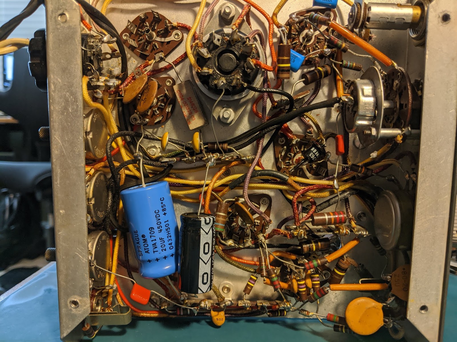
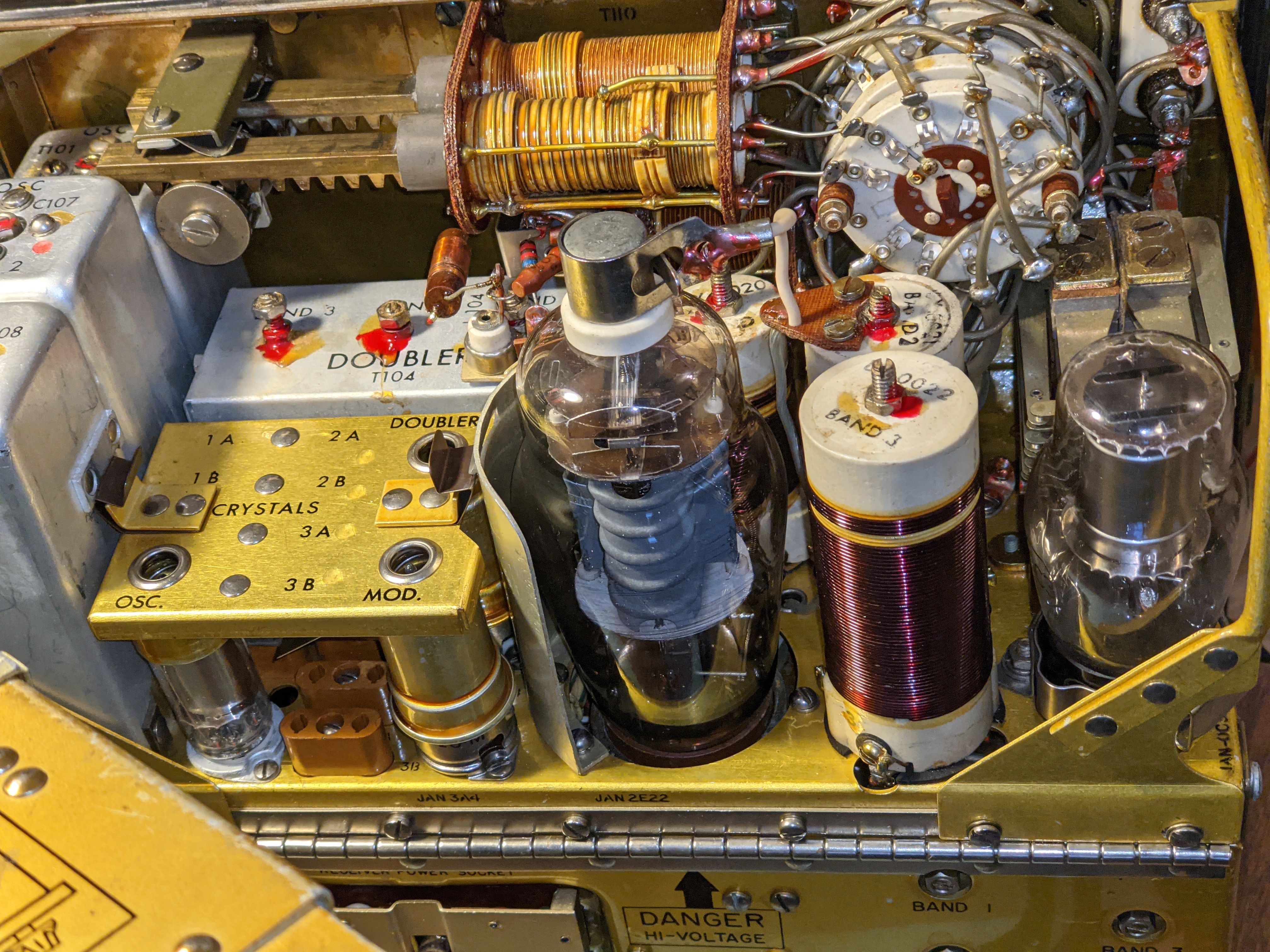
 |
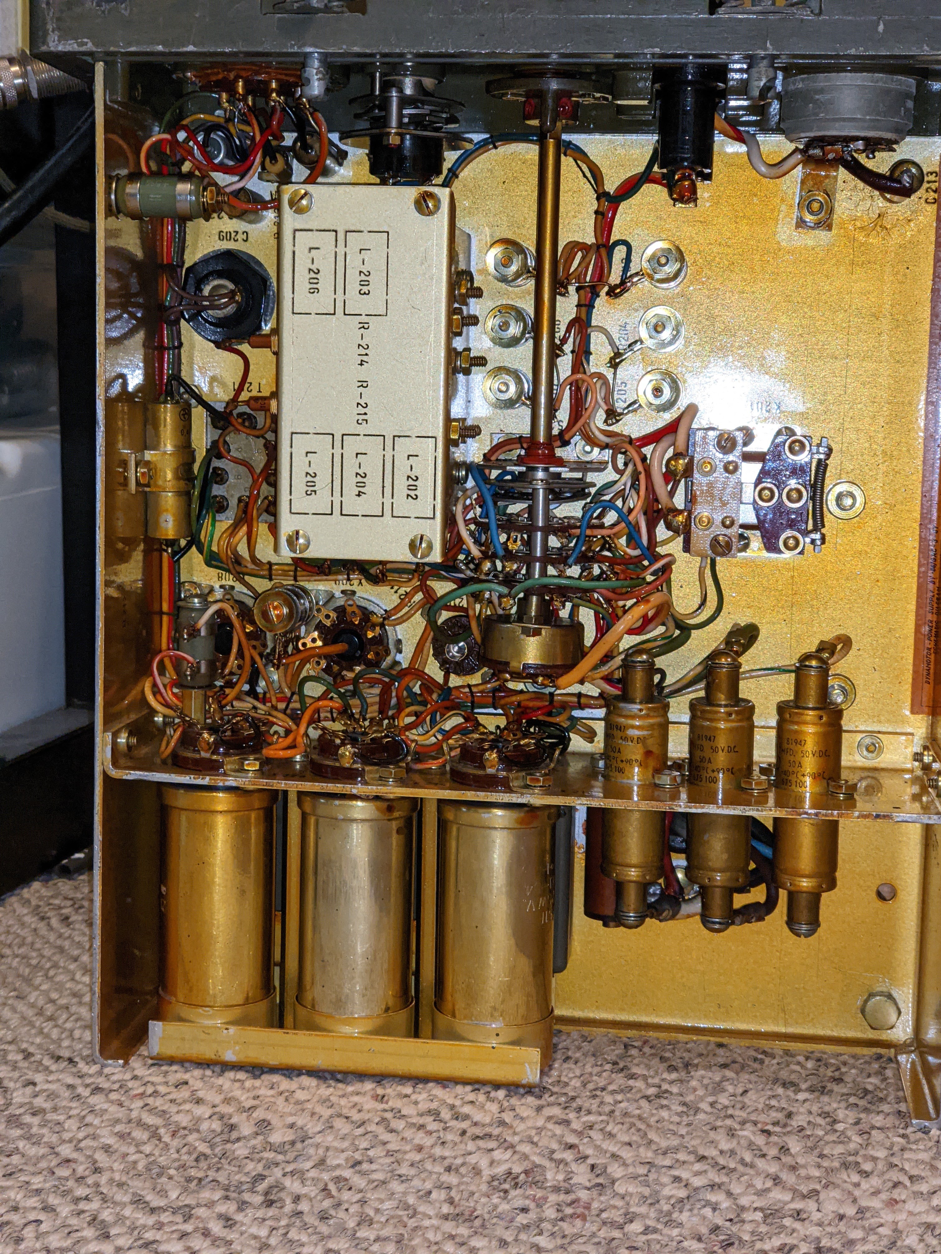
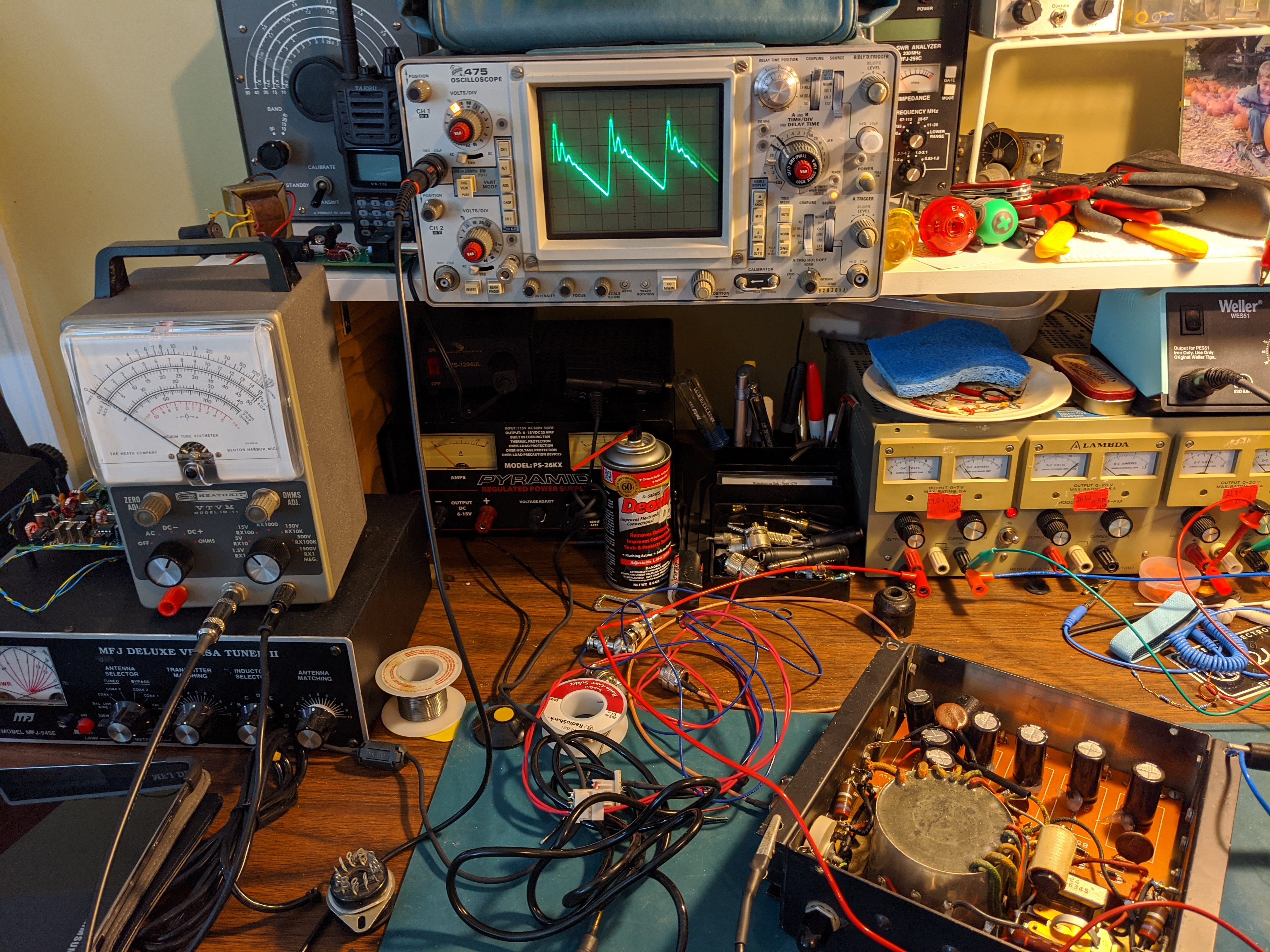
| Out of the case, tracing a low B+ power problem |

Power on the move
- Transmitter Plates -- 475 - 580 v @ 100ma
- Transmitter Filaments -- 6.5 - 6.6 v@ 2 amps
- Receiver Plates -- 105 - 120 v @ 45ma
- Receiver Filaments -- 1.35 - 1.5 v @ 500ma
- Keying Relay -- 6.0 - 6.9 v @ 575ma
That's a tall order for mobile and portable power supplies but designers in the 1940's were quite clever in packing power supply units. I managed to obtain both the hand cranked GN-58 generator with the base chassis and seat for portable operations, and a DY-88 for fixed / mobile operations.
DY-88 mobile power supply
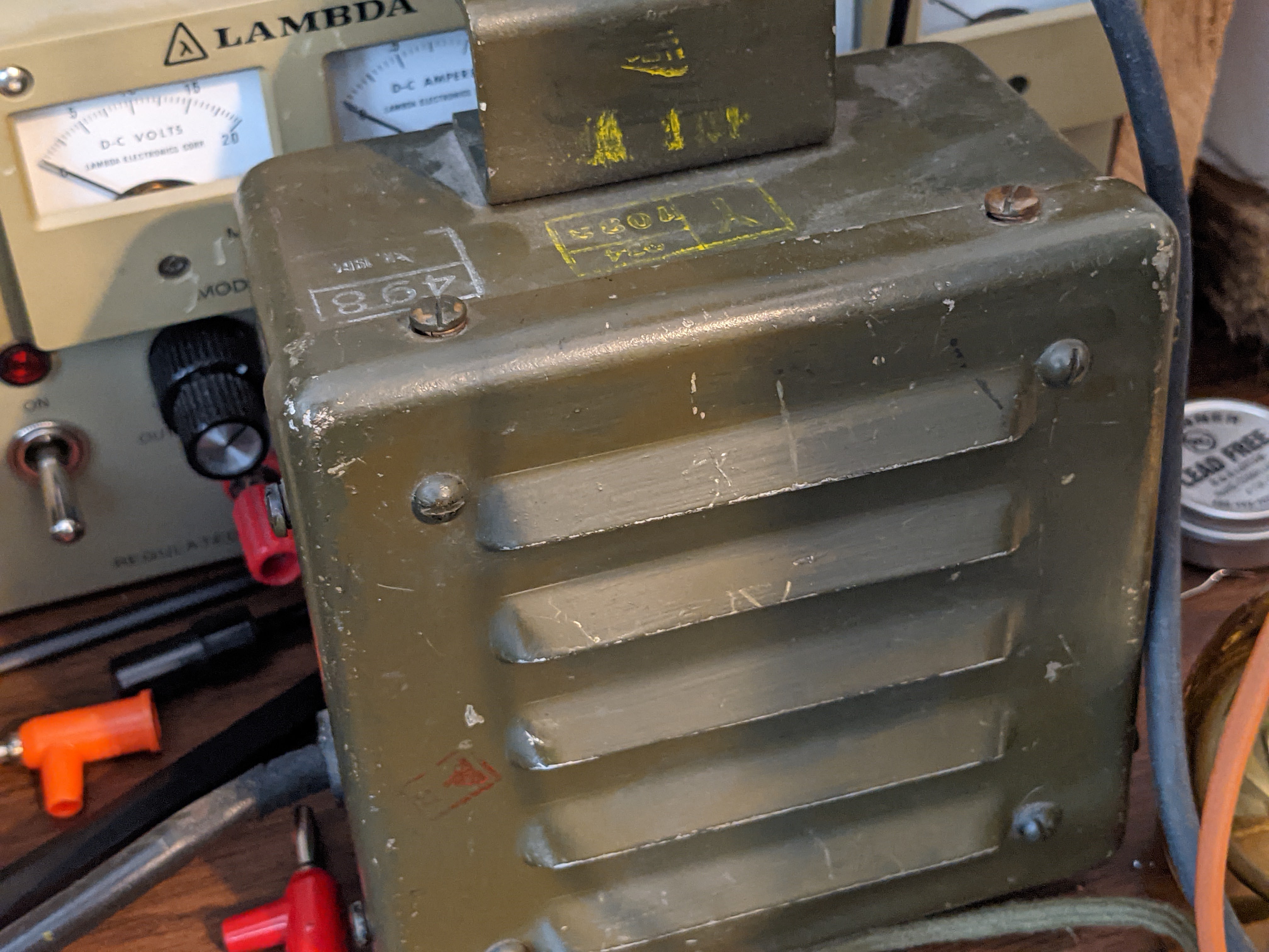
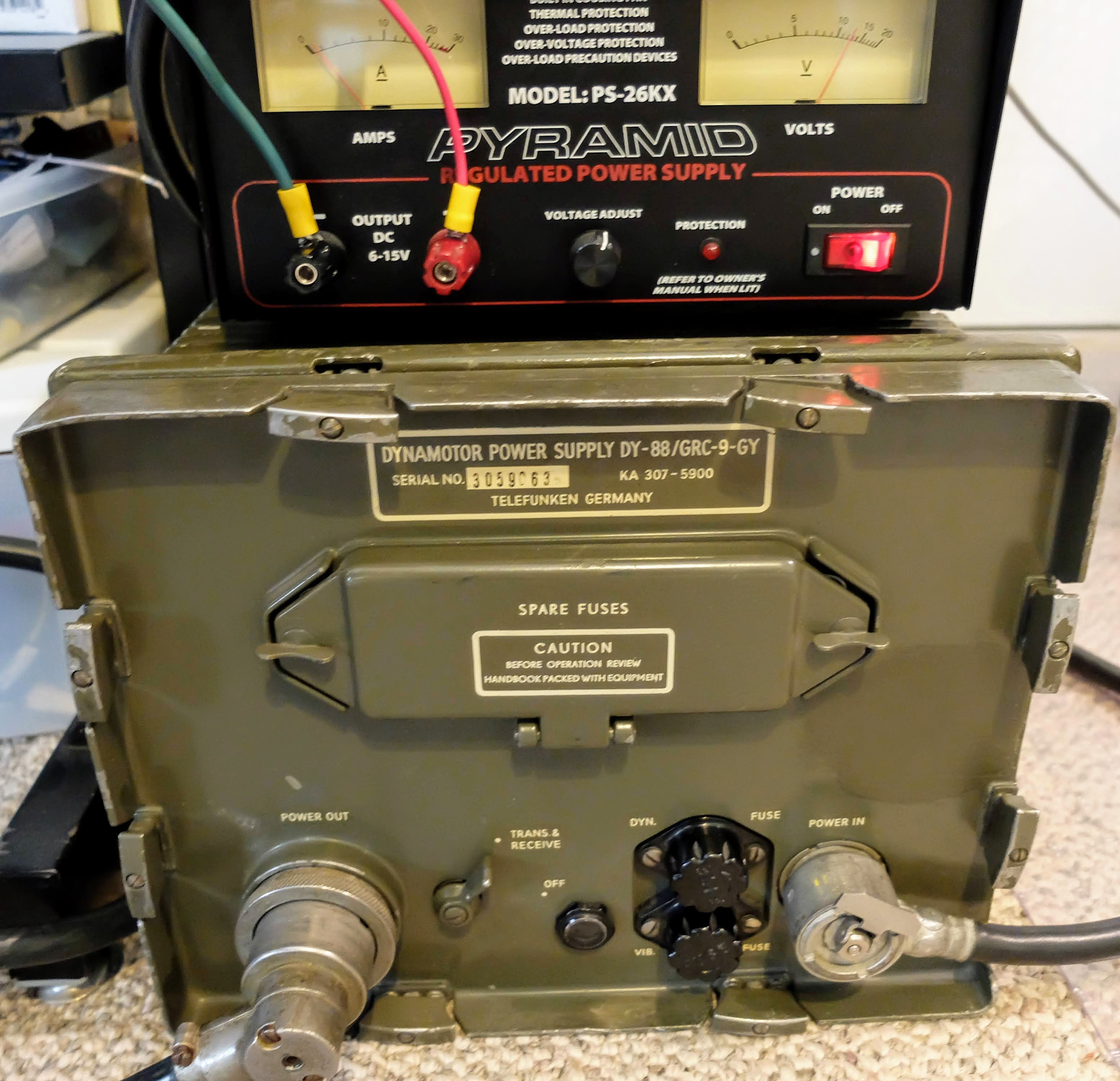 |
| DY-88 set to 12v powered by Amateur 12v supply |
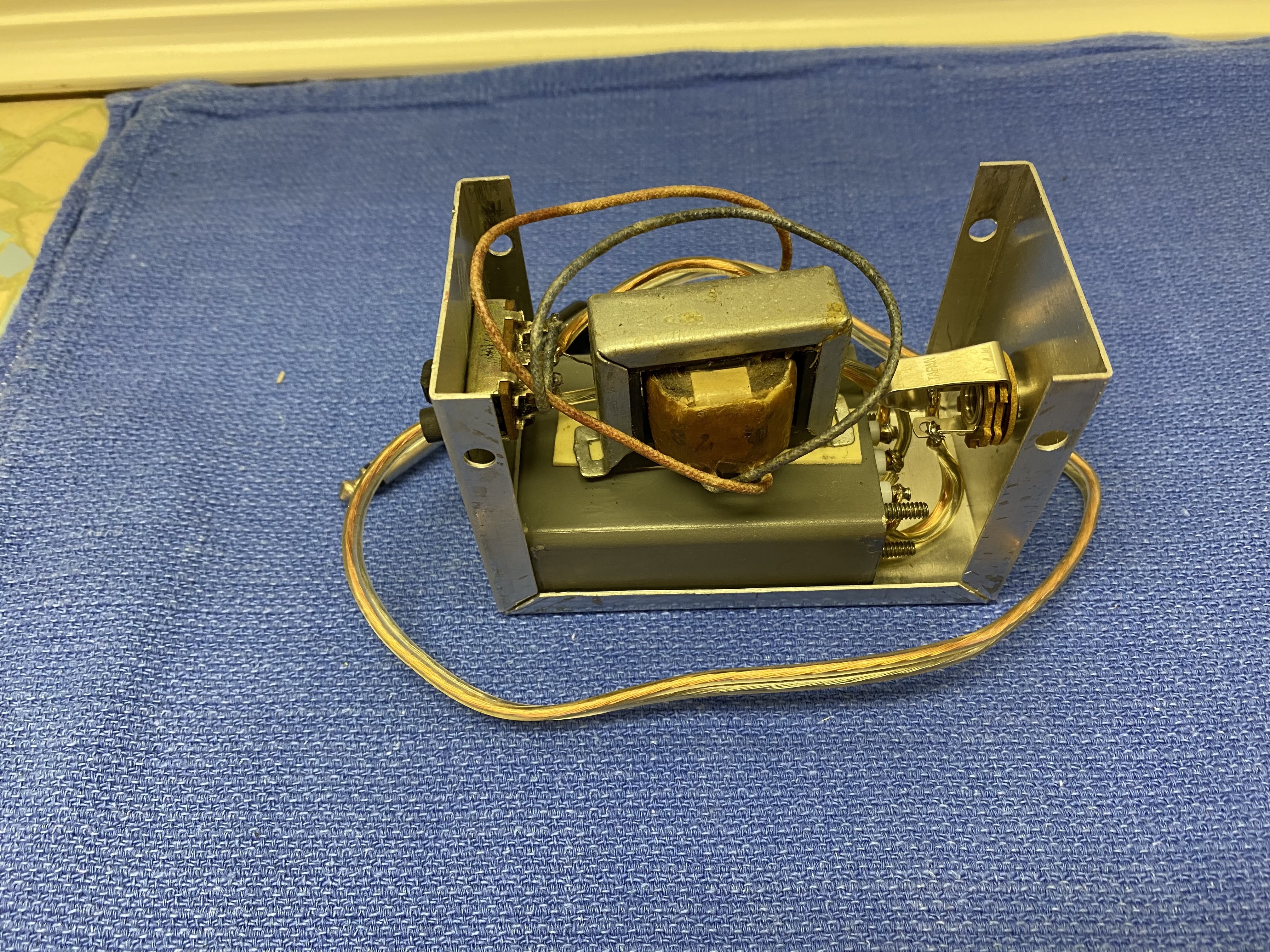
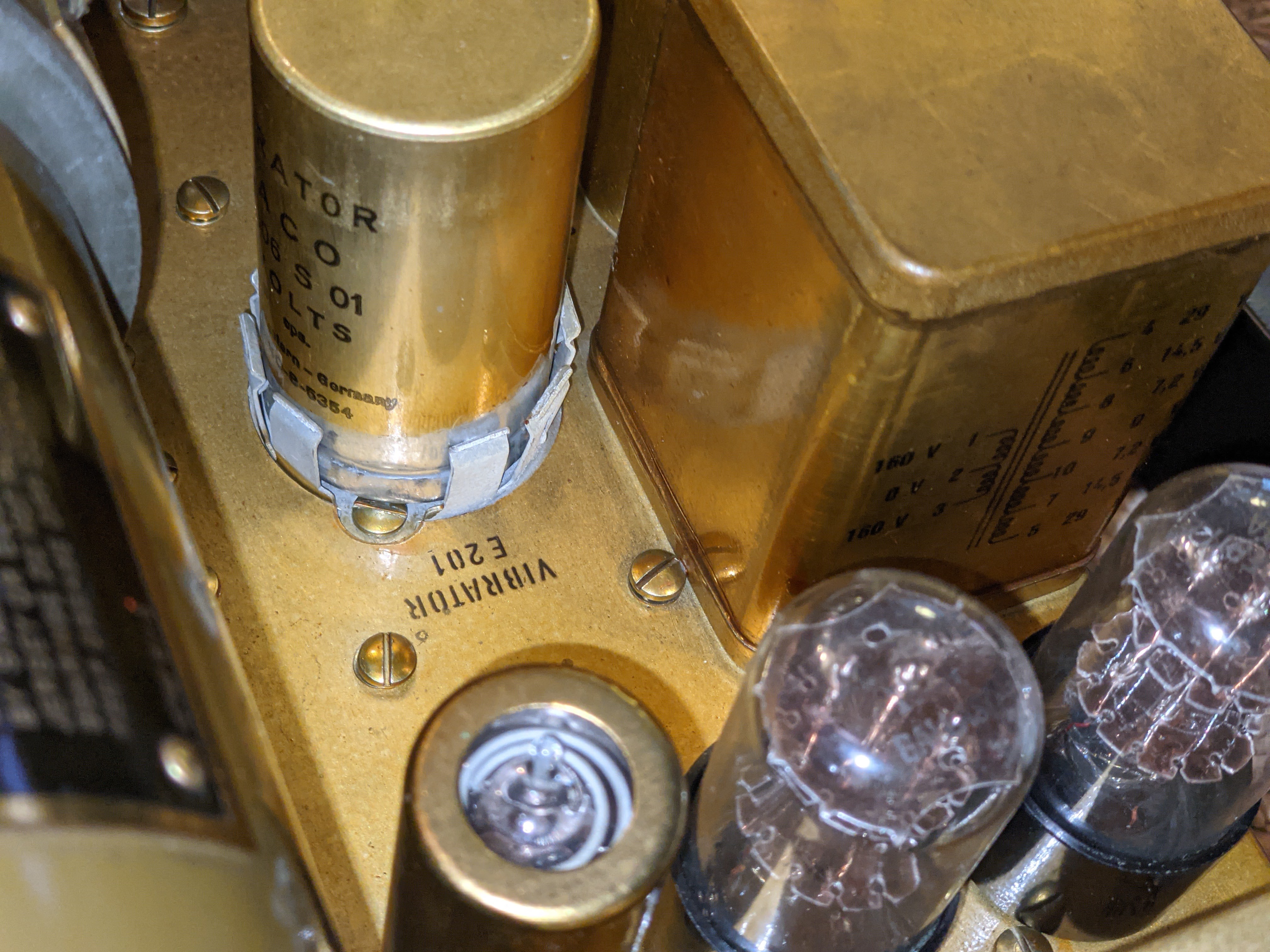
 |
| Vibrator power supply for low B+ |
 |
| Power filtering |
I supply the DY-88 from either an RV battery or an amateur 12v power supply. When in Standby the DY-88 draws less than 1 amp, but placing the radio in Send mode switches on the Dynamotor which draws 12 amps @12v, without key-down and up to 14 amps on high-output key-down. It will drain an RV battery pretty quickly at that rate if the radio is left in Send mode, and works an amateur power supply pretty hard as well. So don't expect to operate remote off a battery alone for too long if your having lengthy QSOs. An added benefit of the DY-88 is that when the enclosed Dynamotor is running you'll have a nice extra 85 dB of generator noise to accompany your listening pleasure.
GN-58 portable field hand-cranked power supply
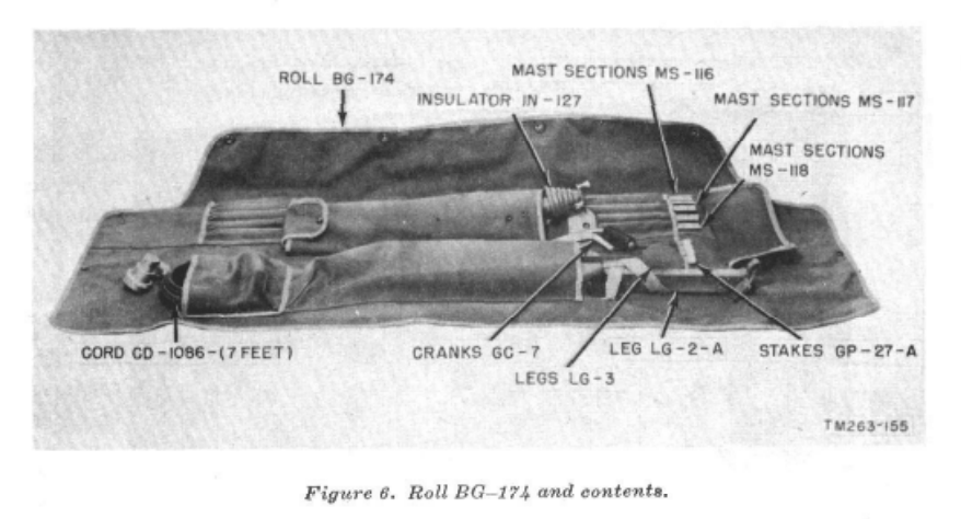
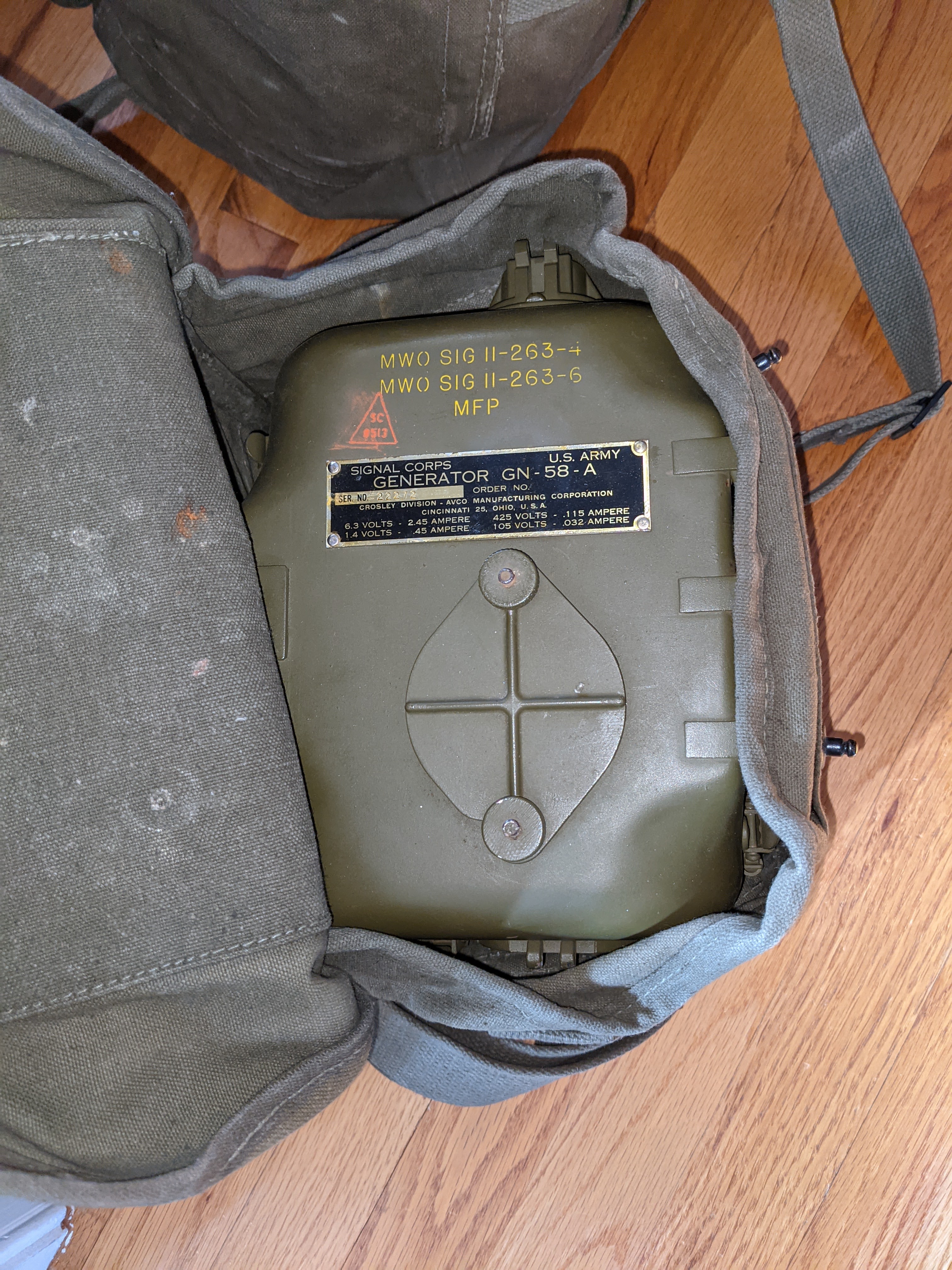 |
| Generator head in carry bag |
 |
| NOS Shiny |
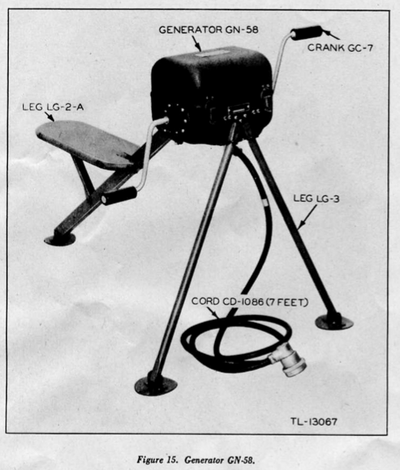 |
| Deployed |
If you have a BC-48 battery hooked up then your human power supply can pause cranking while your receiving. I have a BC-48 battery enclosure that has been gutted of the original, long-dead material and replaced with 10x 9v batteries in series for the low B+ and two D-Cell batteries in parallel for the receiver filament supply.
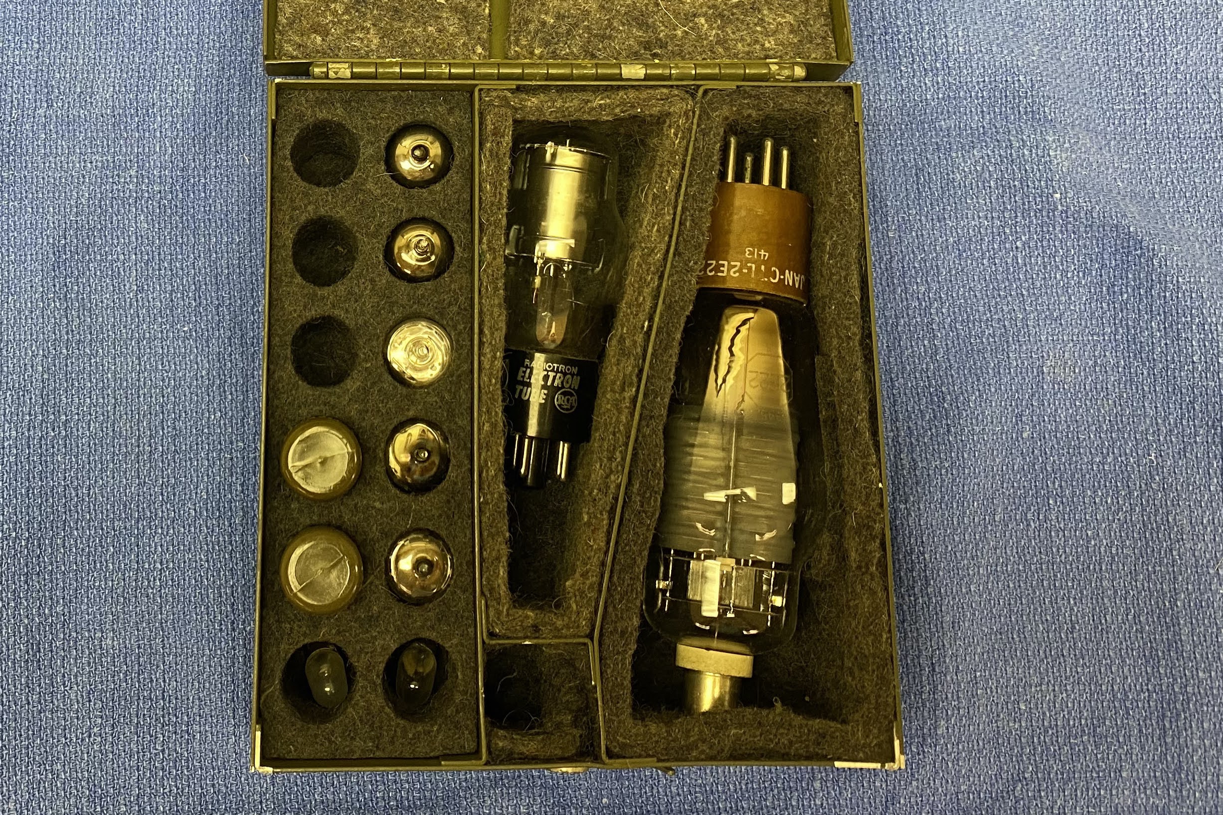
Accessories
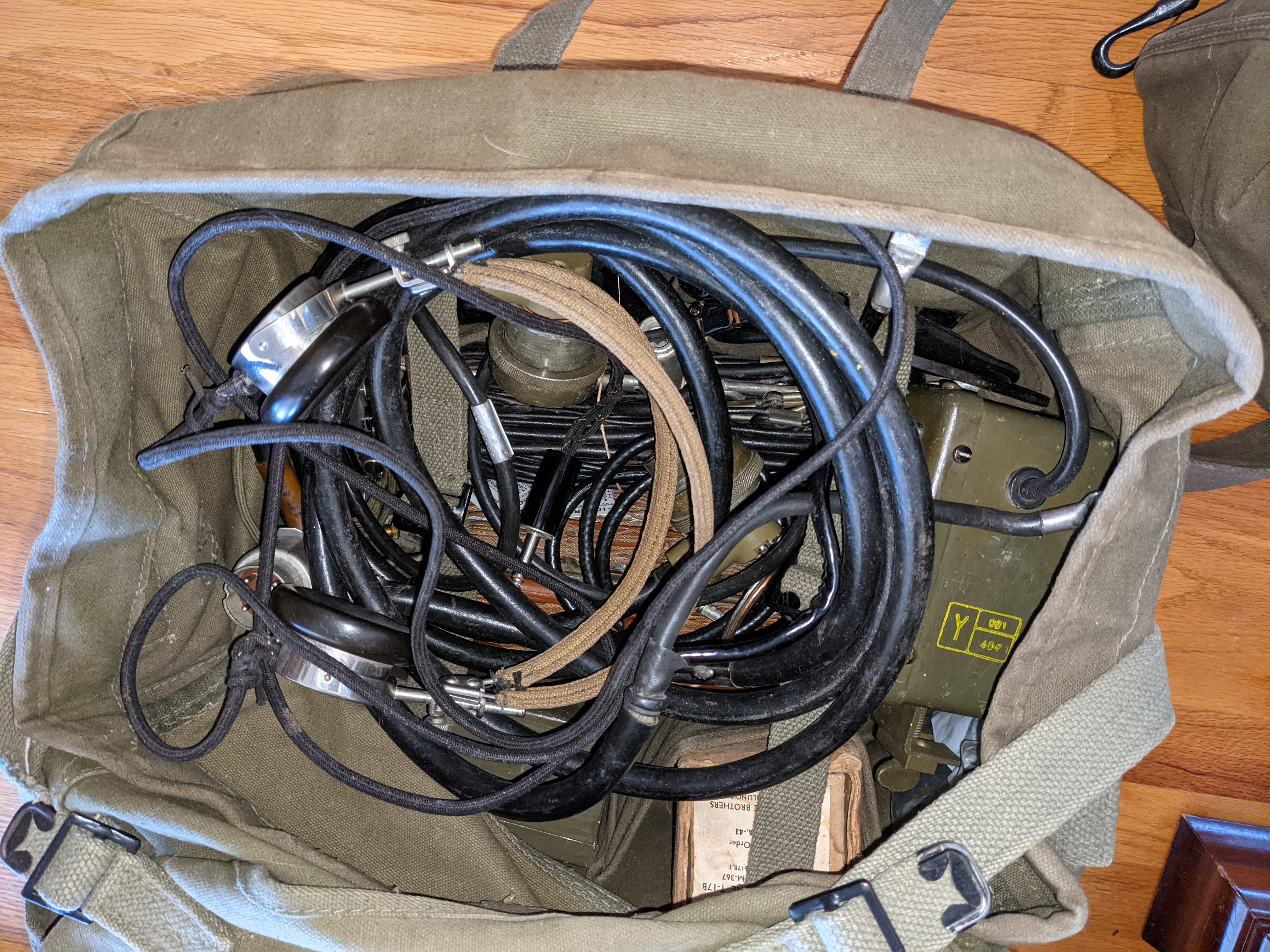 |
| Bag of goodies |
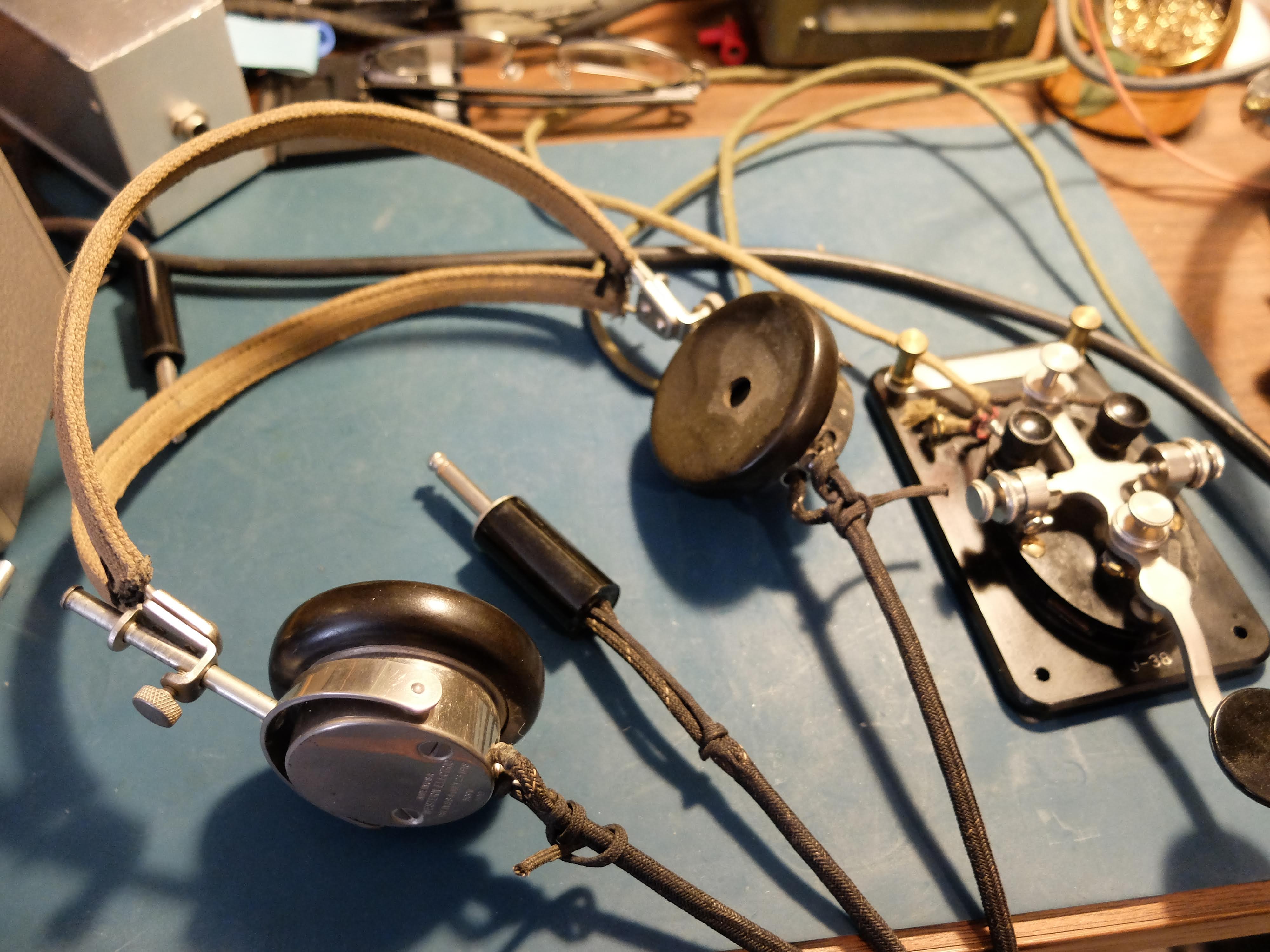
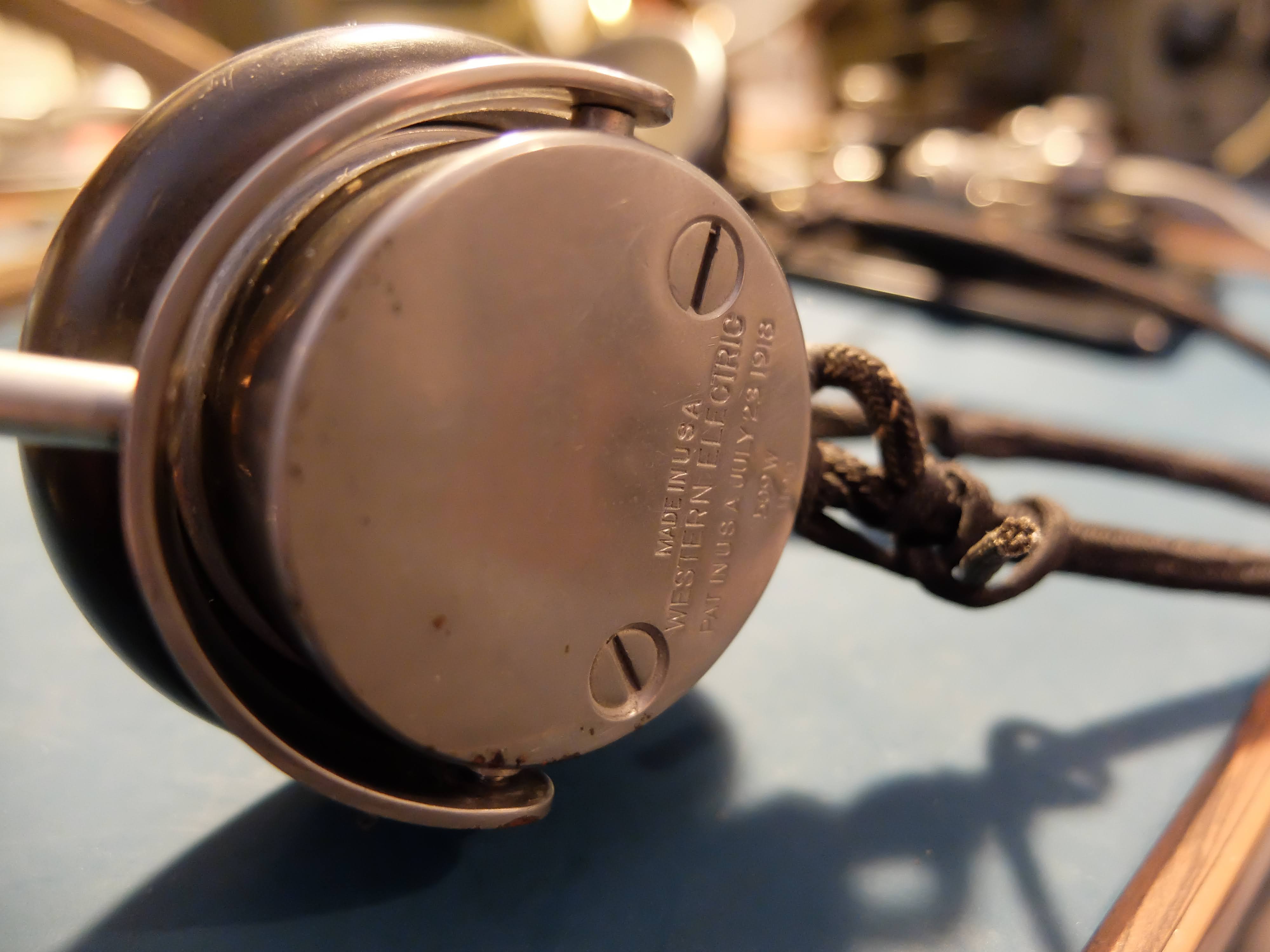
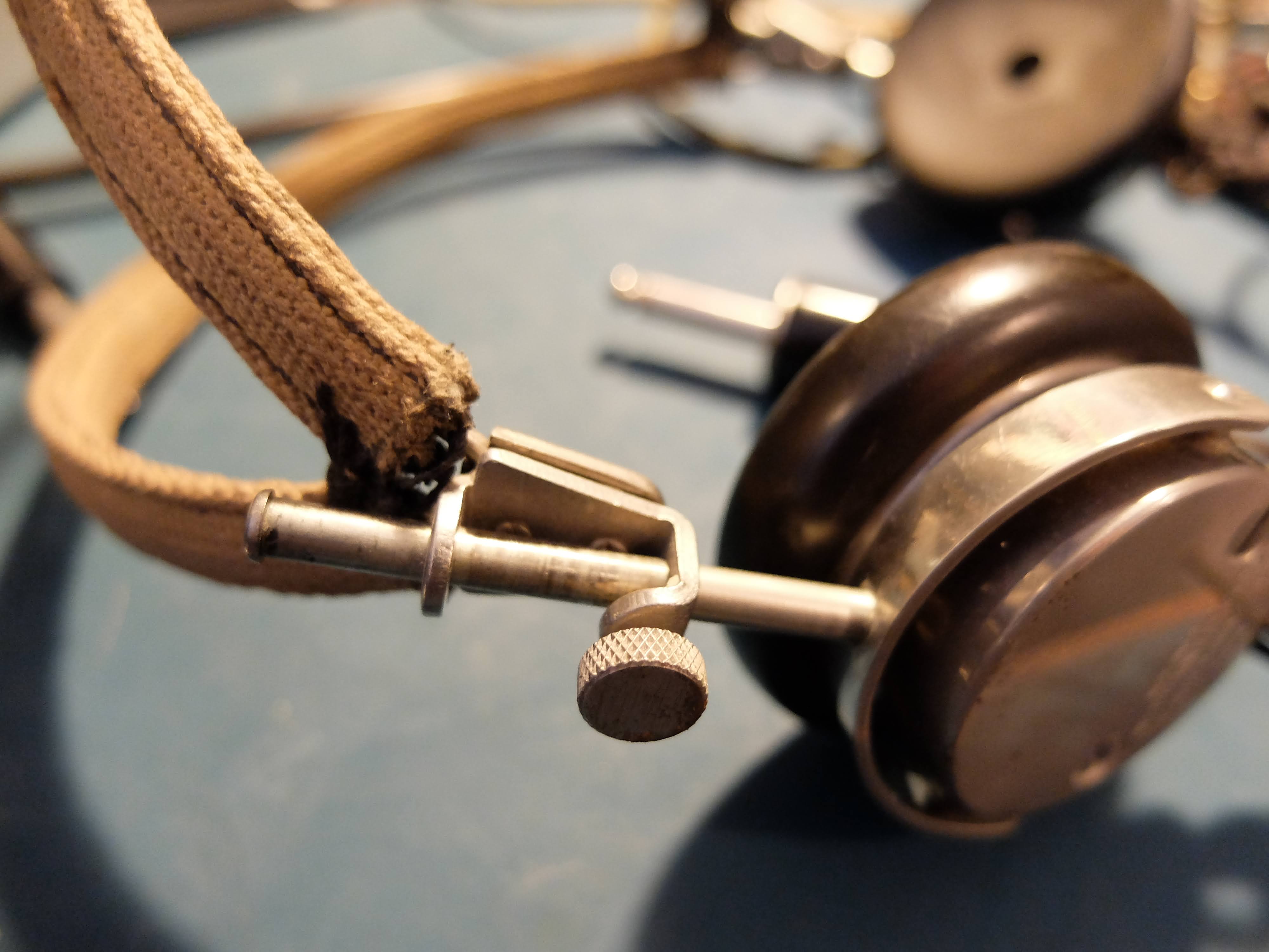
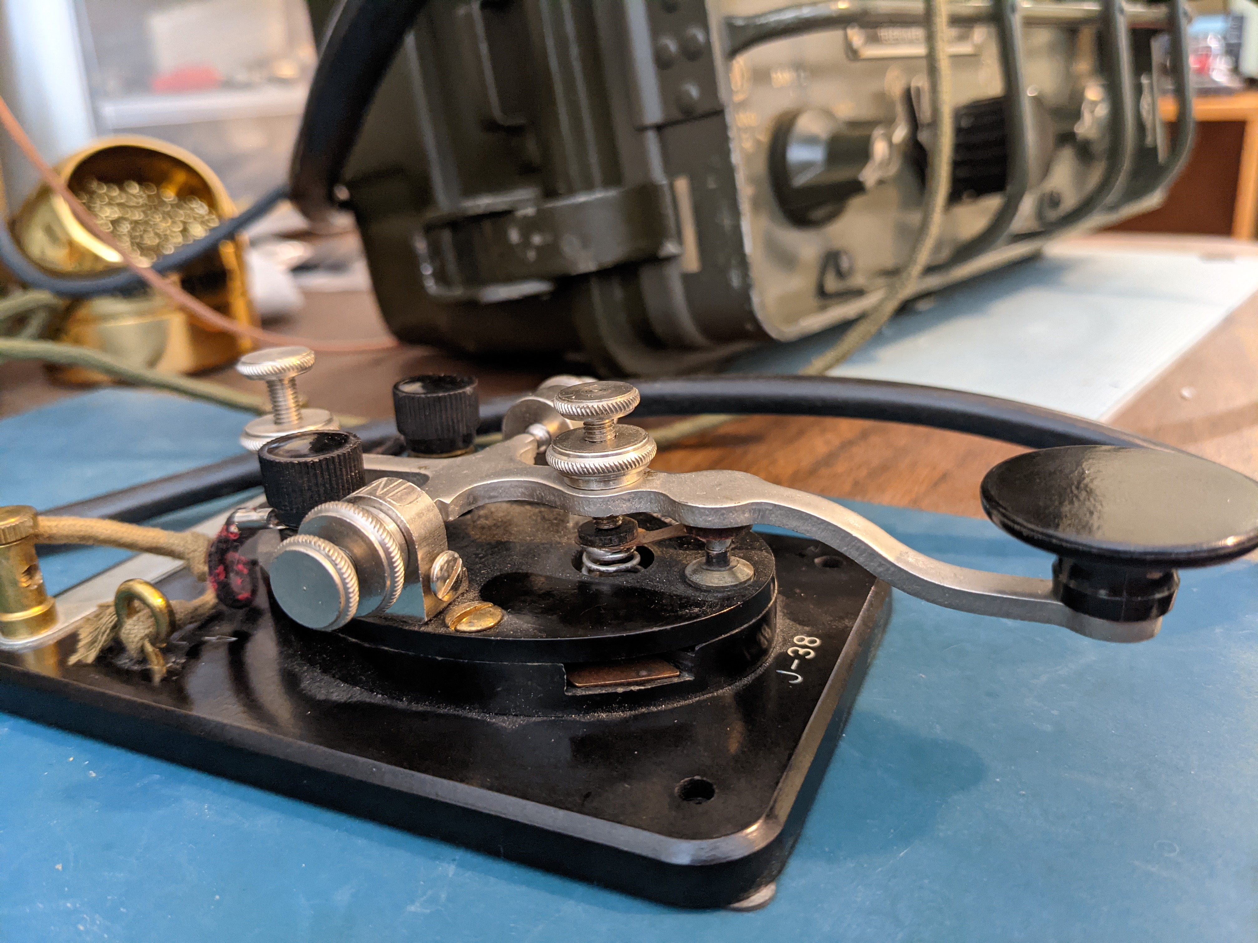
Headphones


 |
| Homebuilt CW filter with impedance switch |
Speaker
Antennas
Spares
More to come
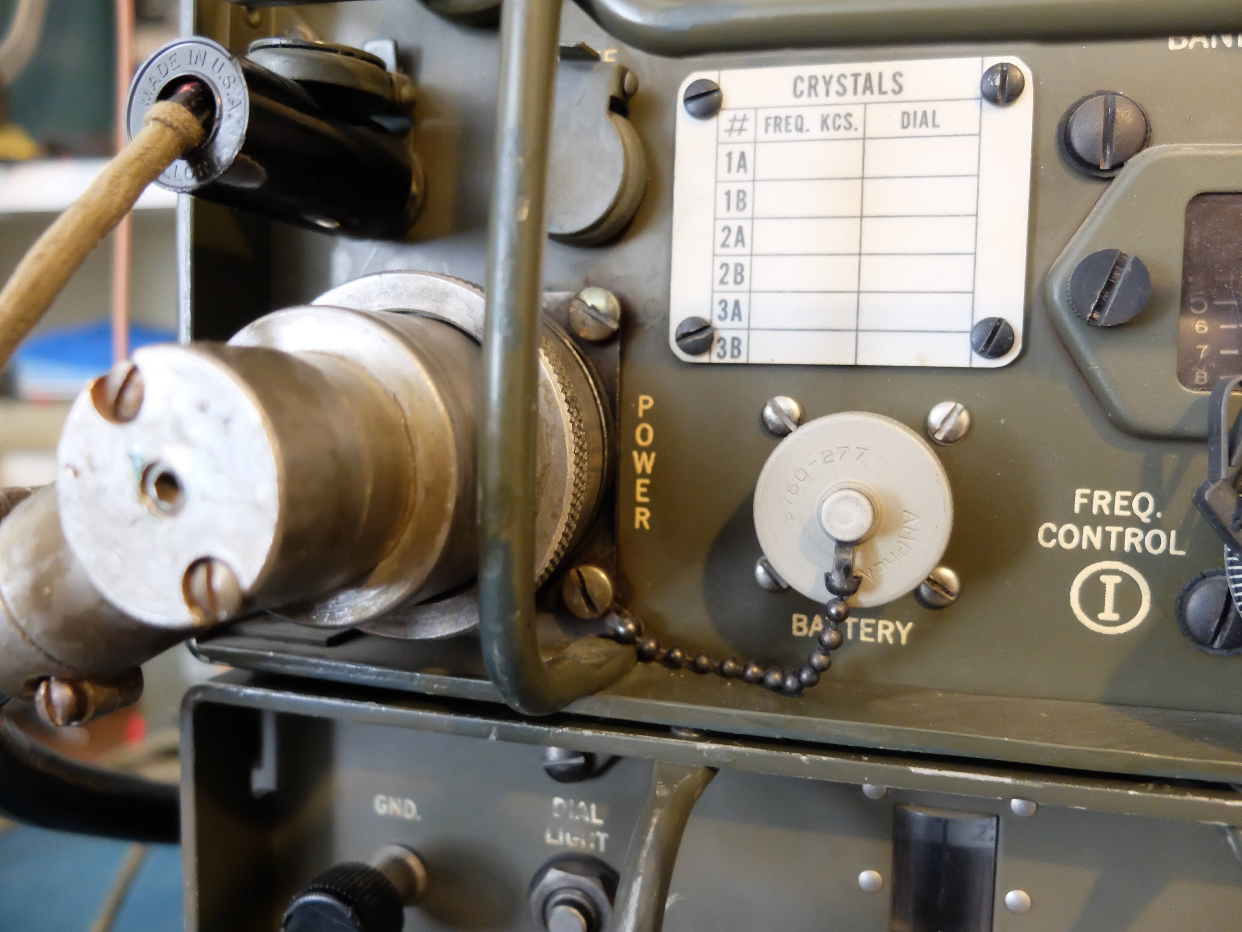
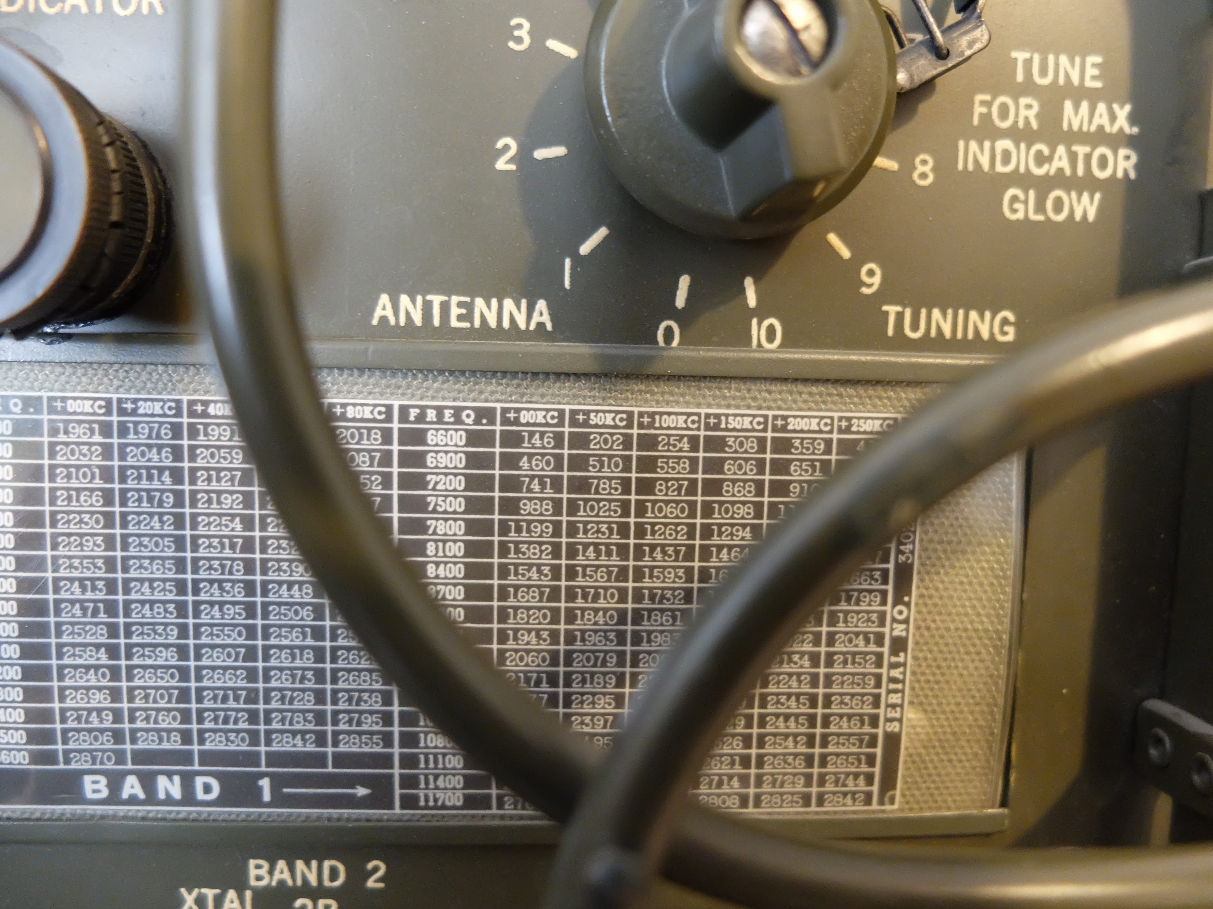
 |
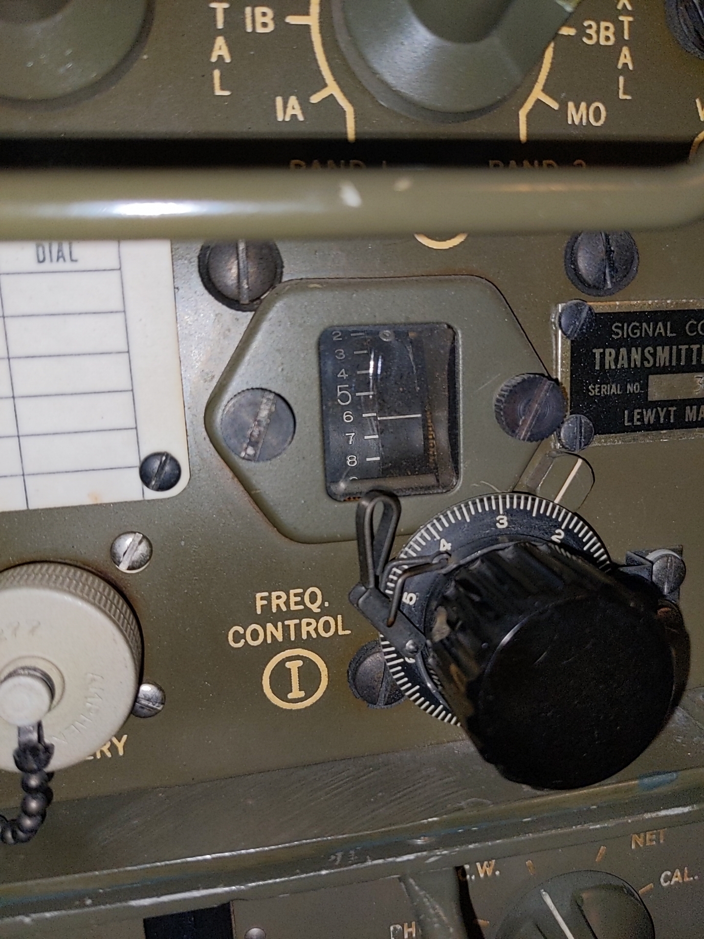
| 50 kHz spacing when reading the frequency on the receiver Note the 7.2 is 7.200 MHz in the 40m band |
Images


Notes
Instructions for restoring a vibrator to operation
Hallicrafters HA-1 Electronic Keyer
High Voltage Electronic Keyer from 1960
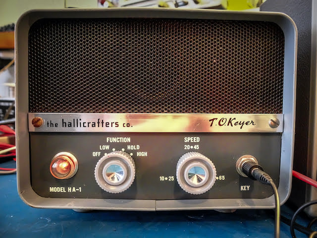
What an electronic keyer was like 60 years ago
A keyer without DIT / DAH memory
That really calls for a change in my paddle usage. My brain needs to keep in mind the length of DAHs so that I don't rush and release a following DIT before the current element completes. This is a bigger problem below 25wpm given the longer length of the DAHs.
The Hallicrafters HA-1 manual states that the keyer is different from other electronic keyers and requires "a knack" to use effectively. I think I've discovered whereof it speaks.
Conclusion
Space in Morse Code
Silence is Beautiful

Proper Space (Timing)
Space between DITS and DAHS in a Character
Space between characters within a Word
Space between Words
How to Practice
When I hear break-in occur between every word I know that I'm putting in a good minimum amount of spacing
Conclusion
DE AA4OO
Regulated voltage for Regenerative receiver project
Mr. Regula-tor
Fortunately, the regen circuit uses a ridiculously small amount of current for B+; about 4 to 5mA. Although I will likely change the audio side of the tube to deliver enough current for a speaker rather than the high impedance headphones in the current design, which may potentially double that to 10ma. For the first incarnation I'll stick with high-impedance headphones.
Generally batteries are used with regenerative receivers because they are so sensitive to power supply noise, but I wanted to give the power supply a shot first and if it proves too noisy I can fall back to battery power for the B+ and just use the filament voltage provided by this transformer.
Since I have a OB2 voltage regulation tube I want to use. The OB2 regulates at 108V so that's what I'm going with. An OB3 would regulate at 90V, but I don't have one of those.
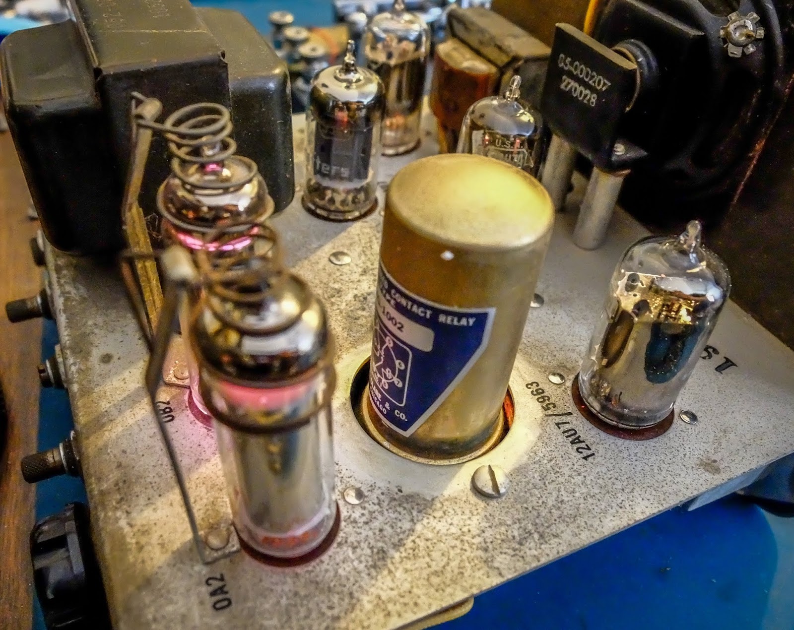
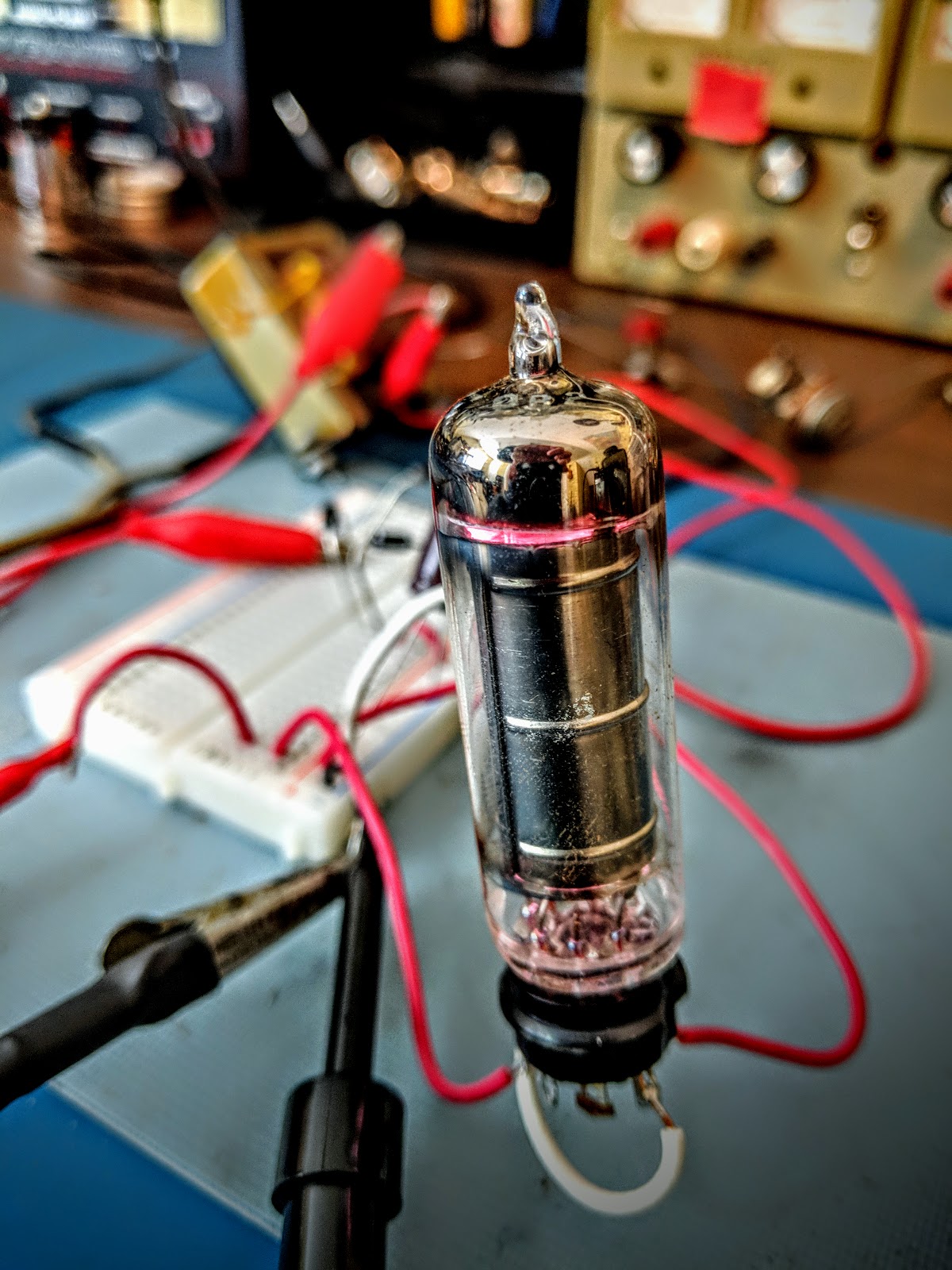 |
| OB2 in action... Glow baby, Glow! |
Calculating the resistor drop
Rdrop = (Vs - Vreg) / (Ireg + Isupply)So, in my case:
Voltage supply (Vs) = 189V
voltage regulation (Vreg) = 108V
regulator current (Ireg) the OB2 requires 5mA to do its job = 5mA
supply current (Isupply) the actual current required by the 6SN7 up to ~ 5mA
So, (189V - 108V) / (0.005A + 0.005A) comes out to a resistor value of 10,100 ohms. 10k is the closest standard size resistor and at 108V it should be able to dissipate 1.166 watts. So I'll need a 10k 2-watt resistor.
Parts is parts

Summary
With the current values I'm seeing 50mA ripple on my regulated voltage.
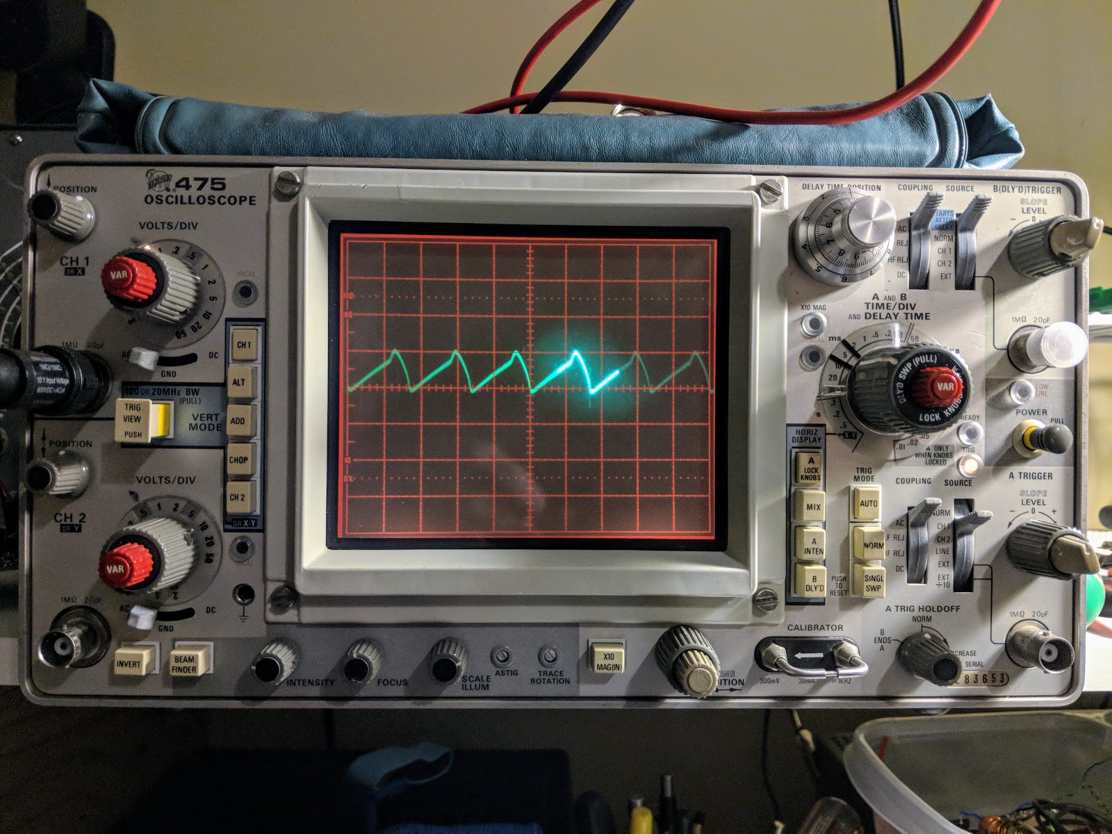 |
| A bit over 50mA ripple |
That's all for now....
So lower your power the old fashioned way, using a voltage regulator tube.
72/73
Richard, AA4OO


