 |
 Remote VFO – Knight V-44
Everyone needs a remote VFO from 1955
Late night eBay surfing, and poor judgement led me to bid on a Knight V-44... and unfortunately won it...
The 1955 remote VFO was unique because it had a built-in power supply. It's also interesting that its base oscillation frequency is in the 160m band. Using harmonics from the base frequency means it doubles for each subsequent band (x2 for 80m, x4 for 40m, etc.) That doubling means it also multiplies the drift. Specified drift is 300Hz an hour. That doesn't sound too bad, but multiply that by x6 up in the 10m band and holy-smokes, it's drifting 1800Hz an hour.Note to self: Never browse eBay just before you go to sleep
That's gonna make operating CW like a game of chase, or hide and seek after every exchange.
This is gonna be fun.
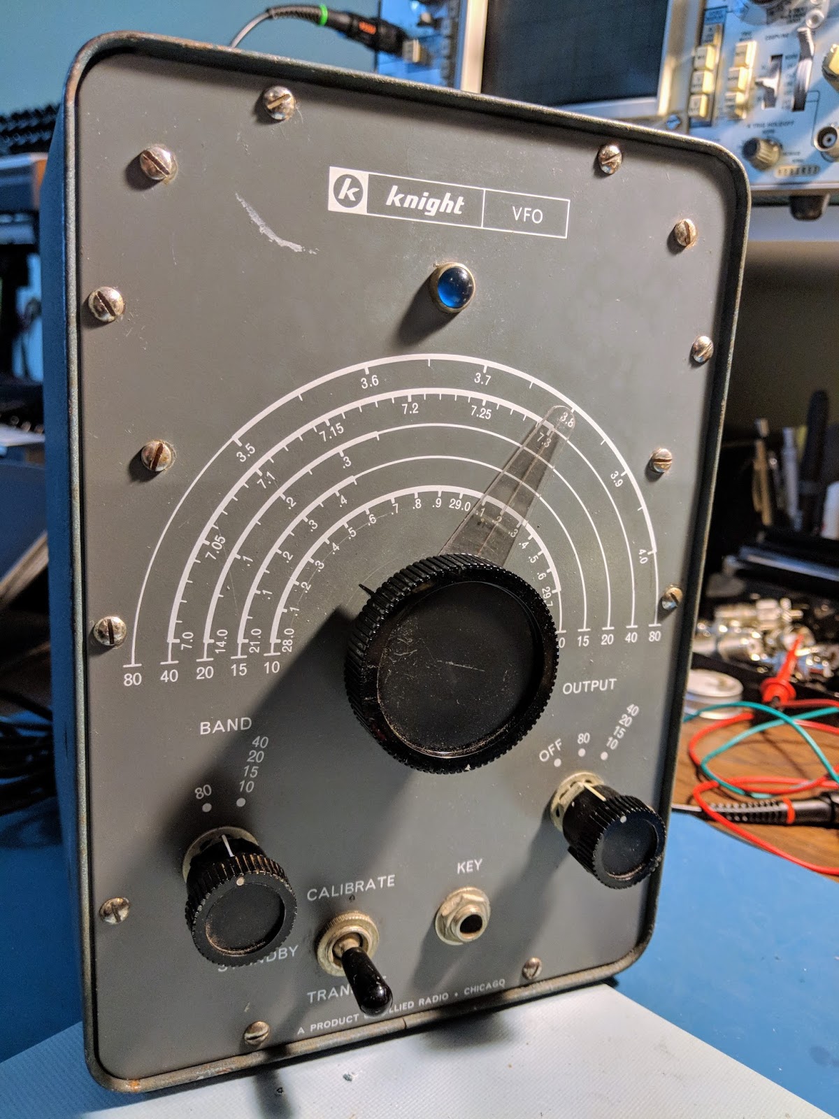 |
| Surprisingly the big dial is actually operating the variable cap through a reduction gear and it's very smooth |
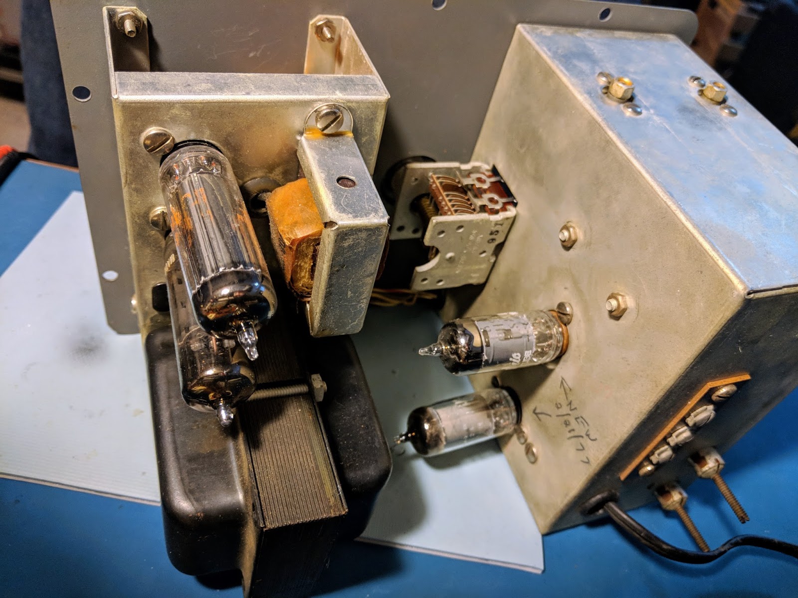 |
| Uses 4 tubes. Power supply up top, VFO circuits in the bottom to minimize impact of heat from the PS. |
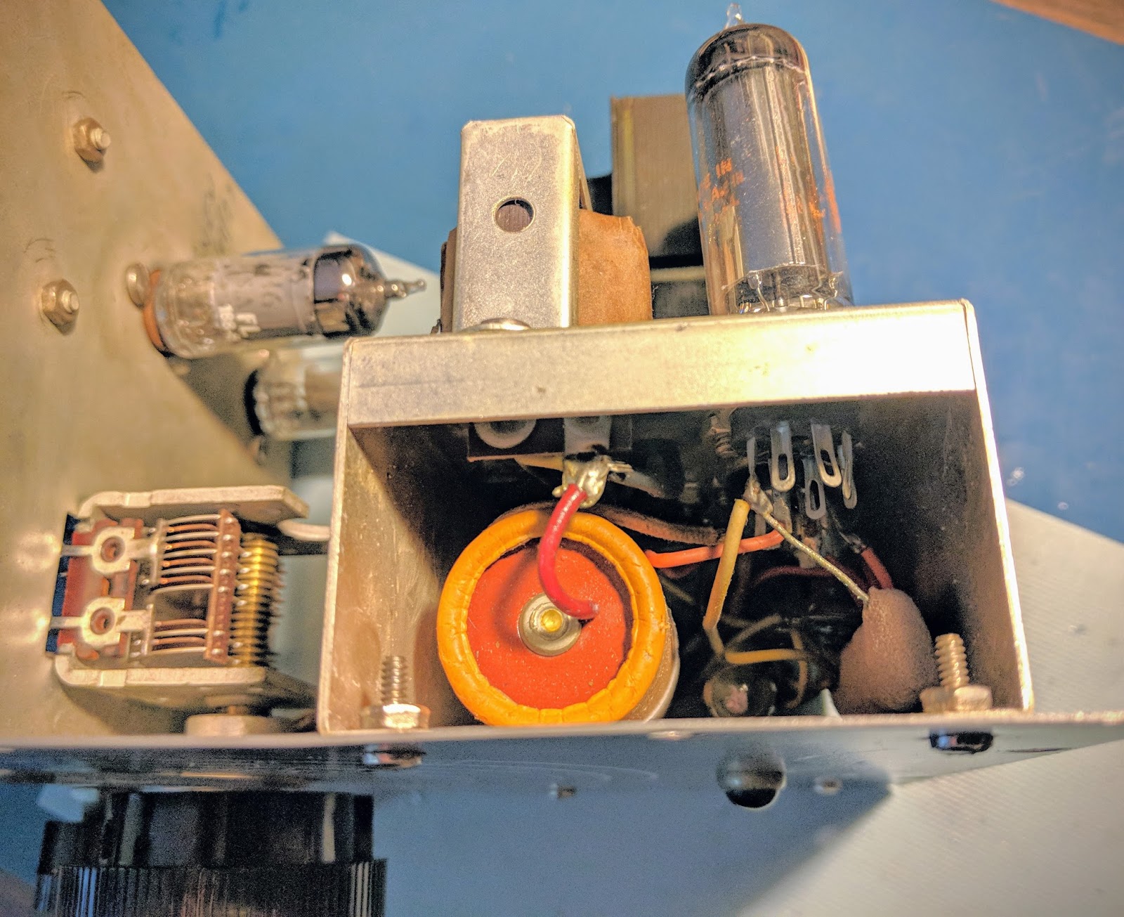 |
| Power supply |
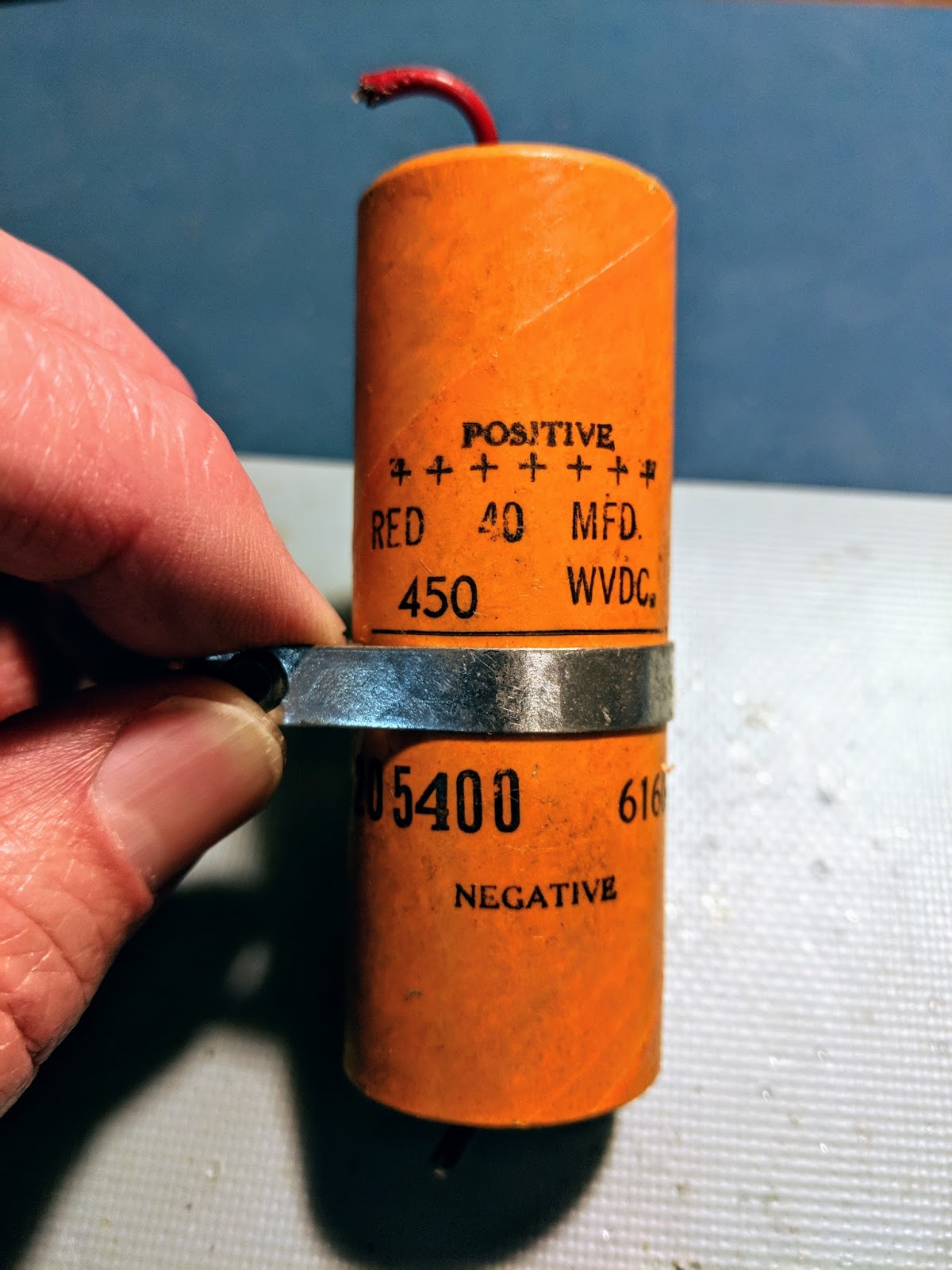 |
| old electrolytic power filter cap must be replaced |
 |
| 10k 7watt resistor had failed |
Replacement bits
The 450v electrolytic cap must be replaced for safety reasons. All the other components measured within 10% of specifications except for the 10k 7w resistor connected to the OA2 tube. It had gone up into mega ohms of resistance, which is likely when the VFO was taken out of use.Handwritten notes inside the chassis indicated the VFO tubes had been replaced in 1977. Until I get the replacement parts for the power supply I won't know the condition of the tubes.
Plans
Surprisingly, it outputs 10 volts of signal, so I may also build an output filter and use it as a QRPp transmitter on its own.
The possibilities are endless.
Update 3/21
Repaired
The replacement parts arrived from Mouser... A 500v 47uF electrolytic capacitor and a 10k Ohm 7-watt resistor. The new high wattage resistor is tiny compared to the giant, defunct resistor that was in there before, and of course the capacitor was about 1/3rd the size of the original. I used some spaghetti on the capacitor leads since the lead lengths were so much longer with the replacement cap. So the power supply section was now repaired.I also replaced the 2-blade, non-polarized, ungrounded, un-fused 1950's power cord with a 3-pin grounded plug and added a 1-amp/250v inline, replaceable fuse. So hopefully there's a reduced risk of death or fire now. Electrical safety didn't seem to be foremost on the minds of kit builders 60 years ago. The size of the 3 wire power cable and it's much thicker insulation didn't fit the opening in the back of the VFO as both the power cable and the VFO output come through the same hole, so I had to remove the insulation and use heat shrink to get things to fit. Additionally the large in-line fuse holder didn't fit well inside the VFO housing so the wiring is quite a bit more cramped in there than it was before.
After the components were replaced and the wiring was complete I plugged it in... no-smoke. Then I flipped the repaired switch (the phenolic disc for the on-off switch was broken in half when I received it), and wallah! The indicator light lit up through its pretty little blue jewel eye. So I knew the transformer was supplying 6.3v for filament. I heard a low hum from the little transformer and then the tubes began to glow. The OA2 was glowing it's pretty violet color, and no bad smells were emanating. I was ready to button it up and begin calibration.
The sparse instructions directed me to back out the tuning slug for the 80m band nearly to the end and screw in the slug for the other bands all the way, so I did so. I set the trimmer caps C1 and C2 to their fully engaged positions.
I carefully re-installed the front face holding the VFO and PS sections it in its heavy-duty case, taking care to get all the new power cord/fuse wiring inside the VFO section from binding up on the sharp edges of the case as it went in. In screwed in the plentiful 10 screws that holds it together and Bob's your uncle. Well, maybe Bob isn't your uncle but I just wanted to say that.
I had already attached an RG-58 coax to the output inside the VFO and run it out the hole with the new power cord, so I then installed a BNC connector on the end of the RG-58 to make hookup easy. I like BNC connectors because they are secure and I have lots of adapters for different connectors. I then connected the VFO output to my Elecraft CP1 RF coupler and terminated the other end with my ugly dummy load. I connected the RF coupled cable to the Oscilloscope and turned everything back on.
Calibration
I let it warm up 20 minutes or so. The cabinet does not get very warm, just about 15 degrees above room temperature. That's actually a good thing, from what I've read. If the VFO is at room temperature then it's more susceptible to the variations of that room temperature. Having the case stabilize above room temp can make the VFO more stable.I had my frequency counter attached to an output from the oscilloscope. In the 80m band setting with the VFO dial set to 3.5 Mhz the freq-counter was reading around 1.75'ish. The VFO primary oscillation roams around the 160m band and generates the first harmonic in the 80m band. The freq counter had trouble tracking due to all the harmonics, and the output on the oscilloscope was not very pretty because it was showing the primary frequency with the first harmonic interfering.
I was unable to properly calibrate the VFO using a frequency counter, due to the interference from the harmonics, so I turned on my SDRPlay, software defined radio. It can display up to 10 mHz bandwidth but for this test I was displaying 2 mHz bandwidth so that I could easily see the harmonic for the band I was calibrating.
That made quick work of calibration. I adjusted the variable capacitor C1 (near the bottom left hand side of the VFO) for the 80m band and adjusted the one above it for the remainder of the bands. I was able to verify that adjusting the VFO dial in the CW portions of the bands was extremely accurate with regard to frequency.
It appears to work like a charm. I hooked up a key and even sent some test messages and listened to them on the SDR. I'd been advised to not key the VFO directly because it tended to chirp but frequency stability was much better than I expected. Over the course of an hour that I was calibrating I saw very little drift after the initial warm-up.
Here's a little video demonstrating the completed calibration...
That's all for now .
So, warm up your Tubes and spray some RF into the air.
73
Richard ,AA4OO
Please support our generous sponsors who make AmateurRadio.com possible:
 Ham Radio Deluxe |
 W5SWL Electronics |
 Ham Radio Prep |
 KB3IFH QSL Cards  Hip Ham Shirts  HamRadioAuctions HamRadioAuctions Reliance Antennas Reliance Antennas Enigma Shop Enigma Shop |  morseDX  Ni4L Antennas  R&L Electronics R&L Electronics antennas.us antennas.us QRV QRV |
- Matt W1MST, Managing Editor
