Author Archive
 AI Analysis of Logs for Antenna Directionality
Where is this dang thing pointing?

I have made a lot of contacts when portable but I paper log those and they rarely make it back into my electronic logs, so nearly all of these logs are from my station operation and 95% of those have been on the 80m OCF.
Gemini provided me with this evaluation
- 80m: Broad "figure-8" pattern with maximum radiation broadside to the wire at 55° (NE) and 235° (SW).
- 40m: A "four-leaf clover" pattern. Your strongest performance is at 45° and 315°, perfectly hitting Europe and the US Midwest.
- 20m: Four sharp lobes that pull closer to the wire axis. Your log shows high-gain "spikes" at 35° (Europe) and 330° (West Coast).
- 10m: Eight or more very narrow lobes. Your 10m contacts are extremely directional, primarily clustering at 50° and 130°.
- 80m, Broad Figure-8, Strongly Biased NE/SW: Contacts cluster at 55° and 235°. Coverage is broad but noticeably stronger toward the Northeast US/Canada. High: Matches the broadside radiation of a dipole.
- 40m, 4-Leaf Clover, 4 Strong Peaks: Contacts are highly concentrated at 45°, 135°, 225°, and 315°. You are successfully hitting Europe and the US West Coast via these distinct lobes. Very High: Confirms the 2nd harmonic pattern.
- 30m, Distorted 6-Lobe, NW Dominant: You have a massive cluster toward the Northwest (330°). This band is notoriously asymmetrical on an OCF antenna, and your log shows you've "found" the dominant lobe. Moderate: The theoretical pattern is messy; your data simplifies it.
- 20m, 4 Long, Sharp Lobes, Sharp Spikes: Contacts are extremely localized at 35° (Northern Europe) and 330° (Washington/Oregon). This matches the narrowing of lobes as frequency increases. High: Matches the "tilting" of lobes toward the wire axis.
- 17m, 6 Very Sharp Lobes , Strategic Clusters: Contacts cluster at 13° (New York/New England) and 225° (Mexico). The narrowness of these clusters indicates you are operating within high-gain "fingers" of radiation. High: Confirms the 5th harmonic pattern.
- 10m, 8+ Needle-Thin Lobes, Pinpoint DX: You have specific, isolated successes at 50° and 130°. Many other directions show "nulls" where no contacts were made. Moderate: High-QSB (fading) makes this band less predictable.
Conclusions
I did look at some tools for evaluating directionality based on logs such as https://qsomap.org but the ones I found are visual and require manually evaluating the graphics. There are likely other tools that would do what the AI is doing but I'm not aware of them yet. Please leave a comment if there are log analysis tools that you use for this purpose.
Loop on Ground (LoG) Receive Antenna
Dirt Shark Antenna
How a Humble Wire on the Ground Can Transform Your Radio Listening
My Noisy, Old-Faithful 80m OCF
Receive Only Antennas?
- Magnetic loops- Too fiddly to re-tune when you change bands
- Beverage - Give me land, lots of land
- LNA augmented, phased verticals - Money, money, money
- Loop on Ground - Cheap, but they can't possibly work
Loop on Ground Antenna
How to Make One


Results
Signals are being picked up by the LoG that are lost in the noise and are invisible on the waterfall of the FT-DX10 no matter how much I fiddle with the display gain and display peaking filters. But I can work them when I find them because that 80m OCF is a good performer as a TX antenna.
Conclusion
"Now I see" said the blind man
Begali Intrepid
The Perfect Bug?

A New Design
- The pendulum hinge is at the rear of the key rather than the middle
- The adjustments are all based on magnets rather than springs
- The dwell for the dits has a real control, rather than using various pieces of foam, string or clips to change dwell time
- The dit contact is a sprung plunger that always remains centered on the contact rather than brushing against it at various angles
- The split lever mechanism operates at the center of the key placing the DAH and DIT contacts much closer to one another than a traditional bug
- There is less mass in the pendulum itself than a Vibroplex Bug
- It has a sprung, nylon wheel damper that doesn't clatter
- It weighs a TON (well about 6 lbs) and feels welded to the desk without having to use non-slip material or using spit to semi glue them in place (yech, yes I use spit to hold my keys to my desk)

Preparing for Use

In Use


Conclusions?

Ham Radio – QRP 2023-04-25 01:28:00
TX Relay, Power and TX REQ IN

Wiring the Break Out Box and TX-REQ-IN


Partial Success


Portable Ops in Comfort
 |
| Working my rolling shack portable station from air-con comfort |

 |
| Early try with a military fiberglass pole mast |
 |
| Now I use a Flagpole Buddy with a 30 foot telescoping mast |
 |
| Gone RF fishing with a 30 foot pole and a big sinker. |
 |
| Palm Radio Single Paddle |
 |
| On the Eagle the Palm Radio Single magnetically attaches to the side |
 |
| Note the power and antenna connections under the table |
Benefits of the Yaesu XF-130CN 300 Hz Crystal Roofing Filter
Do You Need That Filter?
The Yaesu FT-DX10 comes standard with a 500 Hz crystal (xtal) roofing filter, but offers an optional 300 Hz roofing filter. Should you purchase the optional filter?

The 300 Hz roofing filter is twice the size of the 500 Hz filter so it must be twice as good right?
If you casually switch back and forth between the two filters on a noisy band, it sounds like the 300 Hz filter markedly improves selectivity and quiets the noise. But try this: Select the 500 Hz filter and narrow the bandwidth (using the bandwidth control) to 300 Hz, then switch to the 300 Hz filter.
When you digitally narrow the bandwidth of the 500 Hz filter to 300 Hz you will "hear" the same reduction in noise as you have cut out 200 Hz of higher frequency sound. Engaging the 300 Hz filter lowers the volume a bit (3-6 dB) due to insertion loss.
So what you are actually "hearing" when you switch back and forth between the filters without changing the digital bandwidth is the reduction of the higher frequency noise that can be accomplished using the bandwidth control alone with the 500 Hz filter.
So, from a selectivity standpointthe 300Hz filter doesn't gain you anything over using the digital filtering with the 500 Hz filter. The real benefit should come in the form of adjacent signal rejection. So let's look at that.
In the video below I demonstrate the signal rejection of a 40 dB over S9 adjacent signal to a weaker S3 - S5 signal.
From the video you can hear that there is a very small demonstrable difference in strong signal rejection when using the 300 Hz optional filter, but the difference is so small that I doubt many of us would find practical benefit over simply narrowing the DSP bandwidth while using the 500 Hz filter. Even when contesting. The digital filtering built into the FT-DX10 is really, really good when using the included 500 Hz roofing filter alone.
Yes, I spent the $200 for the optional filter thinking it would help, but I wished I had known what I do now. I would have $200 for some other nifty radio gadget to spend instead.
That's all for now.
Lower your power and raise your expectations
Richard AA4OO
Yaesu FT-DX10
Shiny new Rig -- Yaesu FT-DX10
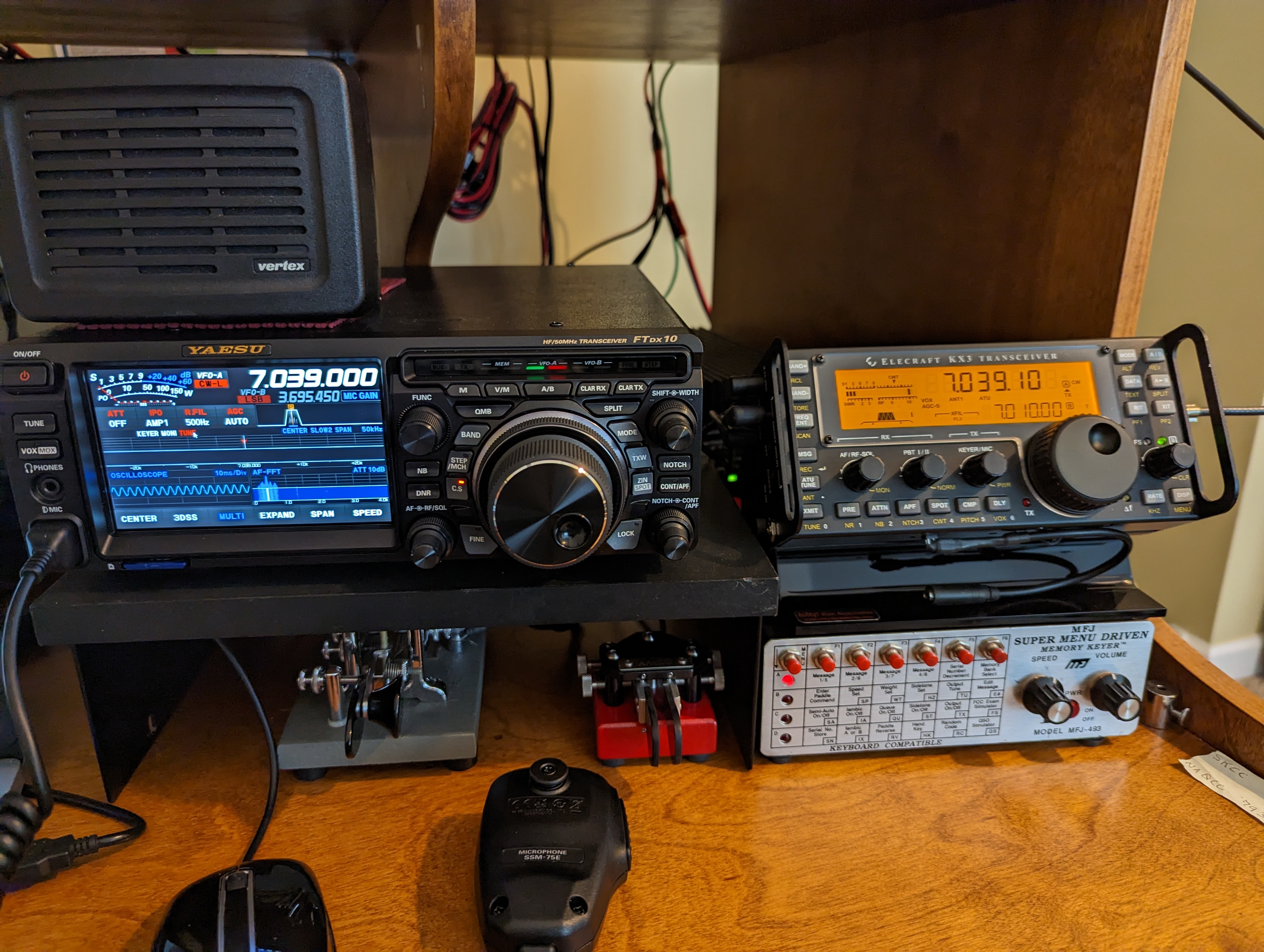 |
| FT-DX10 next to the KX3 |


