Author Archive
 Big Soldering Irons & PL259’s
Like a lot of newer, more inexperienced hams, I have had a fair amount of trouble soldering PL259 connectors to coax. In my previous posts, about my portable station, I need some small coax jumpers to bring the antenna connectors down to the lower front of the box. That portion is not show in my posts yet, as I’ll write about that later when it’s done. I tried my 40 watt Weller thinking it would work, but it didn’t hold enough heat. I have come to realize that PL259’s are big heat sinks. They drain heat from the soldering iron tip, so you need something that can hold a lot of heat. Namely a larger tip on the iron.

In the above picture, are my three soldering irons. The center one is a 25 watt model. It has a pencil type tip. No good for PL259’s but it’s good for other things. The bottom one is a 40 watt model with a small chisel tip. While the tip is larger, it’s still much too small. I know on ham forums on the Internet, there will be someone who will claim they can use this iron and successfully put on a PL259, but for most of us mere mortals, it’s not what we need for the job.
The upper iron in the picture is my new soldering iron. It’s a Weller SP120. It’s 120 watts with a huge tip as soldering irons go. I was able to put two PL259’s on and make a jumper cable in about 10 minutes. Most of that time was spent stripping the coax carefully with my x-acto knife. The right tools are sometimes needed and for me and soldering PL259’s, the right tool is a nice larger soldering iron!
73

Homebrew Buddipole
In a couple earlier posts, I wrote about making a homebrew Buddistick using Budd Drummand’s (W3FF) plans. His plans can be found on his page located here: https://sites.google.com/site/w3ffhomepage/.
I knew when I started building my station that I wanted a couple of portable antennas. I like making things, and decided to give his antennas a shot after deciding that I might be able to actually make an antenna that worked following Budd’s directions. I made the Buddistick first, then later made the Buddipole. Both are easy to make and work well. I use them both (not at the same time) for my main antenna right now, until I can get a full size dipole hung up, and coax run to the house etc. I am fairly new to the HF world and I don’t have my home station complete yet, so these antenna were a quick and easy way for me to get started on HF.

Pictured first are the components of the Buddipole. Starting at the top-left are the two 20 meter coils. To the right, the shorter coil set is for 15 and 17 meters. To their right is the “T” component for mounting the antenna on a painters pole. The black adapter changes the threads from PVC to the painters pole. In the middle are the two antenna whips, mounted in some CPVC with speaker wire coming out of the ends allowing for connections to be made to the whips. The bottom two pieces are CPVC arms with speaker wire running through them, and connectors.
The following picture shows the Buddipole set up with the painters pole extended. The length of the extended painters pole in this picture is about 10 ft.

The plans that Budd published has the coax line ending with the spade connectors. I bought a piece of 50ft coax with PL-259’s installed already on both ends and I did not want to cut one of them off, so I made the following adapter. It is simply a small project box from Radio Shack, with a SO-239 mounted in it and speaker wires connected to the SO-239 center and ground. The orange line is old fly fishing line for hanging the box from the antenna. I use a velcro strip for this.

Here is a table that I made showing how I setup the antenna and the resulting SWR measurements. I think the higher SWR on 20 and 6 meters is due to the proximity of the metal eve troughs that the antenna is near with extended. If I orient the antenna parallel to the gutter, the SWR goes up. My house sits approx SW-NE so pointing the red end of the antenna North puts it at about 45 degrees to the gutter and the SWR goes down. This is the most convenient place to set up the antenna within reach of the radio inside allowing for the 50ft run of coax. The whip column is how many additional sections of the whip I need to extend not counting the 1 section length it is with all the sections pushed in. I think if I got this away from the house a few more feet, the SWR would come down on 20 & 6m.
| Band | Coil | Red Whip | Black Whip | Res Freq | Min SWR | Height | Red Orientation |
| 20M | 20M | 3 + 10 in | 5 | 14.175 | 1.5 | 12 | N |
| 17M | 15/17 | 3 + 1.25 in | 5 | 18.127 | 1.06 | 12 | N |
| 15M | 15/17 | 2 + 2 in | 3 | 21.250 | 1.24 | 12 | N |
| 10M | none | 4 + 5 in | 4 | 28.850 | 1.19 | 12 | N |
| 6M | none | 0 + 4.375 in | 0 | 51.850 | 1.2 | 12 | N |
I have made SSB and PSK31 contacts on 20, 17, & 15 meters. I have not made contacts yet on 10 or 6. Someday I’ll do that.
Below are the graphs from my antenna analyzer showing the antenna setup for each band in the table above.
20 Meter

17 Meter

15 Meter

6 Meter

Overall I am happy with the antenna. I don’t expect it to work like a full size dipole, but for the ease of setup and take down, it’s working for me. I have talked to South America, Europe and all over the US with both the home-brew Buddistick and Buddipoles.
My email address is on my QRZ.com profile. If anyone has questions, I’ll be glad to respond to any email.

Homebrew Buddistick Project – Part 3
I have had a couple of comments regarding the 80m coil for the homebrew Buddistick. I had a few minutes today to set it up and try to get it tuned into 3.897.5 which is the frequency for the Arkansas Razorback Net. I think the 80m band might be difficult for this antenna. I was able to get it tuned to the right frequency with a SWR of about 1.4. But the low SWR “width” is not very wide. It won’t cover the entire 80m band without having to adjust the radial in or out. So I think this would be a very narrow bandwidth antenna on this low of a frequency.
This is the note I got from Budd when I asked about 80m to begin with:
The homebrew Buddistick works well on 80 Meters. Use PVC couplers to allow yourself to go to one inch OD for the coil. The coil length I used Is 11″. Use the same wire suggested for the other coils….insulated wire. Same gauge. If you wind 110 turns on that one inch form, that coil will be about 9 inches long. The single elevated radial will be about 66′ long and the wire should be stored on a kite line winder. This coil, with a Long Whip (9′) on top, should resonate on the bottom end of 80 Meters. Try that info and tell us where it resonates. Your final adjustments will be on the radial. If you want to go up to say 3900 MHZ, take some turns off the coil after you make your initial measurements.
Budd
So the narrowness of the SWR curve was expected. I did turn on my radio to see what I could hear, but tuning through the 80m band, I couldn’t hear anything. Not being familiar with 80m, I don’t know what kind of activity to expected at 4:3o in the afternoon. I won’t give up. I’ll work on it again but it’ll be a few days.
I am still happy with the homemade Buddistick antenna and my homemade Buddipole. I have also made the homemade Buddipole. I will write a post about that in the near future.
K5UNX

Portable Station Build – Part 2
Today I made more progress. I was able to paint the rack. I decided on a camo pattern since the box was sort of camouflaged. Not that I need it to be hidden, it was just for fun. I also mounted the top shelf.
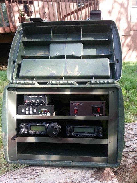
Here is the rack with the radios and other things mounted.

A side view . . .

Top view . . .

View from the back . . .

The box with the rack inserted. The rack won’t be fastened into the box. I am going to be able to slide it in and out as needed. This will make working on things easier. It would also allow me to provide more airflow if it gets warm in the box during operation. I am thinking about putting a small fan in there somewhere. Not quite sure yet . . .
The box with the lid closed. The lid has an “O” ring around the top, making it water-resistant.

I don’t have anything wired up or connected yet. The space on the lower front portion will have a plate with antenna connectors and other things. That will be a project in itself. I’ll post again when I get more done.

Portable Station Build – Part 1
I have been working on putting my radios and gear into a portable box. My goal is a single station that is portable which I can use at home or outside the home. I wanted this setup to be able to be used at things like: Field Day, Communications volunteering for local events, or simply operating at a local park. I don’t want portable gear and fixed station gear at home. I think for me, having a single station that I know inside and out, that could be used in multiple locations suits me just fine. A few guys in our club have talked about doing an informal get together at a fellow member’s farm and spend the afternoon operating. An informal “Field Day” just for fun. I finally have enough done to put up the first post describing my efforts.
For the box that will old the radio gear, I chose a MTM Sportsmen Dry Box called the Spud 7.

Inside the box, I am building an aluminum frame to hold the gear. I am using 3/4″ aluminum angle from my local bog box home store. Also used is some flat aluminum pieces where I did not feel the angle would work well.
Here is the outer portion of the frame.

There will be two shelves. The bottom one will hold both radios, a Yaesu FT-857D and a Paesu FT-8800R. Here is the frame with the radio shelf installed.

The frame is assembled with 1/8″ aluminum pop rivets. I find these easy to work with and they can be easily drilled out if I have to remove and replace something. Some joints have two rivets and other places have one.
The upper of the two shelves, will hold a LDG tuner, a SignaLink USB device and a PowerWerx power supply. Here is the upper shelf. I had it installed but had to take it out to drill the holes for mounting the power supply. The radios will be installed with the mobile mounting brackets that same with them. I ordered the optional mounting brackets for the power supply. So all these things will be held in bolts, nuts, and lock washers. The tuner will be held in with double-sided tape and plastic tie wraps. The tuner is lightweight enough to not move when I tested that solution.
Here is the upper shelf not installed . . . .

The tuner will be on the left, and the power supply on the right.
Once I get the upper shelf in, I plan on painting the frame with a black hammered spray paint. But that’s subject to change . .
The lower part of the frame will be covered with a plate. Mounted on the lower opening, will be a face plate which will have antenna connectors for each radio, power connectors, a power meter and a few other things. I am finalizing the plans for that now. I have it drawn out and designed, I just have to review it again and start ordering the electrical and antenna components.
I will write a Part 2 as I make more progress. I am also going to work on a solar solution for power in the field. That will come later as well.

Homebrew Buddistick Project – Part 2
I earlier posted about building a home-brew Buddistick antenna from the instructions posted by Budd Drummond. I posted the link to his site and instructions in the previous post. Look in the sidebar to the right for a quick way to the last post.
I delayed working on the antenna as I did not have a power supply for my radio so I was in no hurry. Well the power supply showed up this last Friday so Saturday morning, I was determined to finish the antenna and get on the air. The first this I did was finish wrapping the coils and crimp the Radio Shack connectors to the ends of the wires.

Next came long nut coupler which the antenna whip will screw into. A bolt is screwed into the nut coupler and the inserted into a small piece of PVC pipe. The nut coupler was a bit small so I made up the difference with a few wraps of electrical tape as Budd suggested in his instructions.

Next came the short piece of wire with a clip and ring terminal on each end. This is used to connect the top of a coil with the base of the antenna.

I bought a nice piece of RG-8X coax that had PL-259’s on each end. The instructions call for dividing the coax into the shield and center section and attach a Radio Shack clip to each of those. Well I spent a fair amount of money on this cable and did not really want to cut one of the connectors off the cable. I thought it would be nice to have some sort of adapter so I could use different lengths of cable over time if needed. This would allow me to have standard sections of cable with PL-259 connectors on the ends and be more versatile in the long run without having a cable dedicated to this antenna. To solve that problem, I came up with this little thing.

It is simply a chassis mount for a PL-259. I soldered two small wires to the center and outer portion of the mount and then added the blue clips. The center wire goes to the bottom of the vertical portion of the antenna, and the wire coming off the outer part of the chassis mount goes to the radial wire. I used different male/female connectors to avoid being able to connect it wrong so if I start making connections at the top near the whip and work down. Now I can simply attach a PL-259 to this “adapter”. I do plan on putting this little thing in a little box or somehow protecting it somehow. I might post what I come up with later.
Here is the completed antenna without the broom stick that holds it up. I am going to get a painter’s pole from the local home store soon so I can get it up higher than the broom stick.

I also am planning on getting a few tent stakes and parachute cord so I can guy it and make it self-standing if there is nothing available to secure the painters pole to.
So far I have had good performance with the antenna. I don’t have an antenna analyzer so I used an SWR meter and got the SWR as low as I could by adjusting the radial that I tied off to my fence across the yard. On 20 meters, I heard stations from both the east and west coast of the US along with scattered stations in between. I also heard Mexico, Canada, and a station in Istanbul, Turkey! I made a few contacts around the country and in Mexico. The guy in Turkey had a huge pile up so I didn’t get to work him. Considering this was the first time I have ever been on HF, I am sure there will be other chances. I then tried 40 meters. Again using the SWR meter I adjusted the radial to get the lowest reading and went to work. Again I had good results hearing stations around the country. I have yet to try any other bands yet but I will at some point in the future.
I may post a part 3 later if I learn something more about its use. . . . I would like to post a picture of it setup but it’s raining today. Maybe I’ll add that in the near future.
I also need to get a real kite winder for the radial wire as I doubt the cardboard will last very long. I also am planning on getting liquid electrical tape to finish things off a little nicer. And the last thing is to try to mount the chassis adapter maybe in a little box or something better than just hanging it with zip ties.
NOTE: I have decided to add a 80 meter coil and lengthen the counter poise. I’ll add a post about those results when I am done.
K5UNX

Homebrew Buddistick Project – Part 1
This is the first post about my project to build W3FF’s Homebrew Buddistick antenna. This is Budd Drummond’s design which is documented on his homepage. The plans for this antenna are on his web site.
I am a new Ham Radio Operator and am just getting my feet wet with HF. I have a Yaesu FT-857 sitting in a box waiting for a power supply and an antenna to get me on the air. I wanted to build an antenna that would be fairly easy to make as well as not very costly. After a fair amount of research, I settled on this for my first HF antenna. It looks like it’ll be easy to set up and take down as needed as I intend to use it for Field Day, and any other times I am out in the field. I really don’t intend on being tied down to a home station. I am going to build up a portable station of some sort.
My first step was to collect the parts. I spent a few weeks picking up bits and pieces. This first picture is what I bought in terms of hardware components. I did not find the 1 1/4″ bolts that Budd specified, so I bought 1″ and 1 1/2″ versions and will figure out which to use as I make that part of the antenna.

The PVC components are pictures below already cut and drilled per the instructions.

The next step that I am going to tackle is cutting the wire for the coils and wrapping them.
In the following picture, I have started wrapping the coils. A couple are done and I still have a couple more to do.

While doing this, I found that it’s important to wrap the coils close together tightly as the longer coils were pretty tight getting all all the wraps in between the holes that were drilled for the tag ends to go through. The easiest one was the 20m coil. The toughest was the 60m coil with 82 wraps. After wrapping the 60m coil, I had to work the wire wraps down again to get all the wraps to fit.
I’ll post more as I go . . .


