Posts Tagged ‘WSPR’
 Finally some WSPRing with the Alexloop.
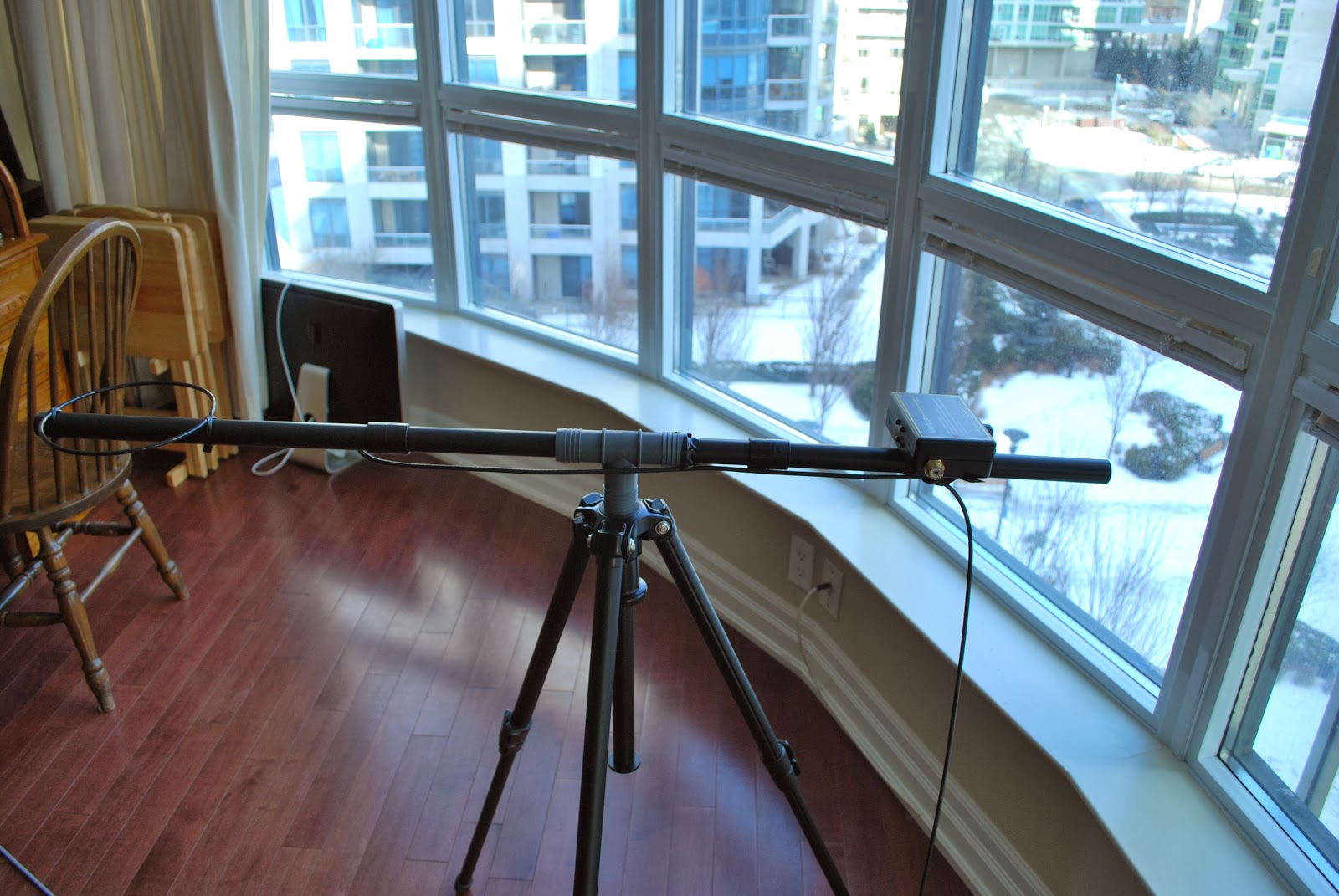 |
| A shot of the loop with the "T" fitting |
I finally set things up to get WSPR up and going, so yesterday during the day and then into the evening I was WSPRing to see how my signal was getting out from the condo. Up to this point I have only used the Reverse Beacon Network or RBN which involved CW at 5 watts. I was not thrilled with the results and was really wanting to give WSPR a go. During the day I tried 10m and 20m I started out with 1 watt and in terms of WSPR that is some pretty high power. The antenna once again was the Alexloop in the horizontal position, at first attempt on both bands the Alexloop was indoors. It was not surprise that there were no spots at all it was time to move the loop out onto the balcony. Once setup I went back to 10m and it was about 2pm local time with no results again. I then jumped over to 20m and it was just U.S stations and very few I might add that received my signal. It was time to pack it in for the afternoon and some chores had to be done and I would get back on in the evening hours.
At 7 pm local time I was up and WSPRing on 40m and with great hopes as the band sounded good and I was decoding some WSPR DX such as EA3NEI. I once again was only heard in the U.S and this time I used up to 5 watts!! Maybe it was that conditions were poor out this way as they have been over the past week. Over the weekend if I get time I am going to give WSPR a go once again and see how it works out.
Whispering with 20mW
Many people who operate the weak signal mode WSPR use too much power. If you don’t use very low power (QRPp) you’ll never find out what this mode is capable of. So to remind myself I thought I’d do some whispering on 10m using 20mW of power. It’s easy to use low power with the Elecraft K3 as the power level is adjustable in 0.01 watt increments.
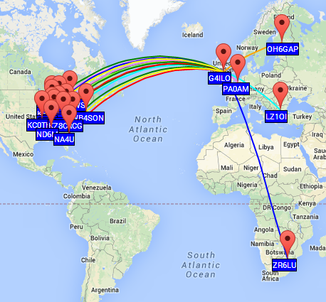 |
| 10m stations hearing or heard by G4ILO on 8 Jan 2015 |
It’s a pity that the WSPRwebsite can’t display a map showing only spots of one callsign. The map shows spots involving one callsign. sent or received. So the map shows WSPR signals I decoded, not only those who heard me. Some of those stations were using as much as 37dBm – whatever that is in watts. Here are the stations that decoded my tiny signal. My 20mW into an attic diopole made it across the pond on several occasions
| Timestamp | Call | MHz | SNR | Drift | Grid | Pwr | Reporter | RGrid | km | az |
|---|---|---|---|---|---|---|---|---|---|---|
| 2014-01-08 15:44 | G4ILO | 28.126104 | -24 | 0 | IO84hp | 0.02 | W9HLY | EN70mt | 5930 | 291 |
| 2014-01-08 15:24 | G4ILO | 28.126112 | -21 | 0 | IO84hp | 0.02 | KZ8C | EM88pm | 5973 | 287 |
| 2014-01-08 15:24 | G4ILO | 28.126104 | -27 | 0 | IO84hp | 0.02 | K4RCG | FM08xl | 5688 | 284 |
| 2014-01-08 15:06 | G4ILO | 28.126103 | -24 | 0 | IO84hp | 0.02 | W8AC | EN91jm | 5649 | 289 |
| 2014-01-08 15:06 | G4ILO | 28.126110 | -18 | 0 | IO84hp | 0.02 | KB9VLR | EN54vj | 5845 | 296 |
| 2014-01-08 15:06 | G4ILO | 28.126144 | -19 | 0 | IO84hp | 0.02 | ND6M | EM55se | 6594 | 289 |
| 2014-01-08 14:56 | G4ILO | 28.126106 | -21 | 0 | IO84hp | 0.02 | KB9AMG | EN52tx | 5964 | 295 |
| 2014-01-08 14:46 | G4ILO | 28.126167 | -22 | -1 | IO84hp | 0.02 | KC9YSR | EM69il | 6175 | 291 |
| 2014-01-08 14:38 | G4ILO | 28.126106 | -18 | 0 | IO84hp | 0.02 | VE3SWS | FN06ge | 5201 | 293 |
| 2014-01-08 14:18 | G4ILO | 28.126098 | -26 | 0 | IO84hp | 0.02 | K9AN | EN50wc | 6175 | 293 |
| 2014-01-08 14:00 | G4ILO | 28.126101 | -28 | 0 | IO84hp | 0.02 | ZR6LU | KG43av | 9468 | 152 |
| 2014-01-08 13:40 | G4ILO | 28.126015 | -7 | 0 | IO84hp | 0.02 | LZ1OI | KN22id | 2470 | 113 |
Watts conversion
The original version of K1JT’s WSPR software had pop-up “tip” windows that showed the power in watts when you hovered the mouse over the dBm setting. Very useful for duffers like me that can’t do a watts to dBm conversion in my head. The new version WSPR-X doesn’t, however.
I found (or more truthfully Google did) an online watts to dBm converter on the web which I have duly bookmarked.
Arduino, WSPR and AD9850 DDS experiments
Christmas is thankfully behind us so I can get back to what I enjoy doing once I have reorganised my workshop.
As you know I am currently developing a potential High Altitude Balloon (HAB) project and have been experimenting with the Arduino microprocessor platform and have constructed a basic prototype.
With the arrival of the GPS module(s) I have had it successfully working and even took it out for a test walk in the local area, receiving the data and uploading it to the UKHAS habitat system.
NERD-1 and Boris have just been for a walk, first time NERD-1 has had proper GPS and running on batteries. #hab pic.twitter.com/RaKsf1rQhr
— Andrew Garratt M6GTG (@nerdsville) November 23, 2013 This project has revitalised my interest in 'hobby electronics' and I have ideas for a number of other Arduino based projects and have been splashing out on components from eBay. Just before Christmas I purchased an Arduino Mega board, this has more I/O pins than the current Uno and specifically some extra hardware serial ports.
Do any internet search for Arduino based amateur radio projects and it will results in numerous mentions of projects using ultra cheap DDS modules based on the Analog Devices AD9850/AD9851 chipsets.
DDS means Direct digital synthesiser and is a type of frequency generation which can be used for creating arbitrary waveforms from a single, fixed-frequency reference clock. Read the Wikipedia page for more details.
In a nutshell the AD9850 is a chip that under microprocessor control can produce a sinusoidal wave from about 1hz to 40mhz. In other words it is an accurate microprocessor controlled VFO (Variable Frequency Oscillator) or signal generator.
VFOs are the main building blocks of radio receivers and transmitters, so not surprisingly a lot of projects have utilised these modules, rather than the traditional means. Intrigued I ordered a couple of these modules for the pricey sum of £3.50 each!
Using information on George Smart's (M1GEO) website and Simon Kennedy's (G0FCU) blog I quickly had a simple WSPR beacon running!
Experimenting with Arduino and AD9850 DDS and GPS unit.. pic.twitter.com/rxDHQQ1aFd
— Andrew Garratt M6GTG (@nerdsville) December 29, 2013 The Arduino uses the GPS module borrowed from NERD-1 for accurate time and then controls the output of the AD9850 DDS to generate the WSPR signal.Before anyone panics I know at the moment I only hold a Foundation Amateur Licence so the construction of homebrew transmitters isn't allowed. This 'beacon' has no power amplifier and the antenna consisted of an inch or so of wire on the DDS output. I was able to verify the operation using my SDR receiver in the same room.
Construction of commercial kits is allowed under my licence so I have ordered a Ultimate3 QRSS kit from Hans Summers for the pricely sum of £17.50! This uses the same DDS module and same microcontroller as the Arduino.
In the meantime there is also more information and ideas on Eugenr Marcus' (W3PM) webpage about the use of these DDS modules, including making frequency reference sources and calibration using the GPS module.
My new year resolution is to get my Intermediate Licence as soon as possible.. but it has been great to get down to some proper experimenting...
Cannot beat a picture of an oscilloscope to look techy.. my DDS experiments continue... pic.twitter.com/T9OLHOdTLW
— Andrew Garratt M6GTG (@nerdsville) January 1, 2014 10m still lively
Still seeing plenty of transatlantic stations on 10m WSPR. I wonder how long it will last?
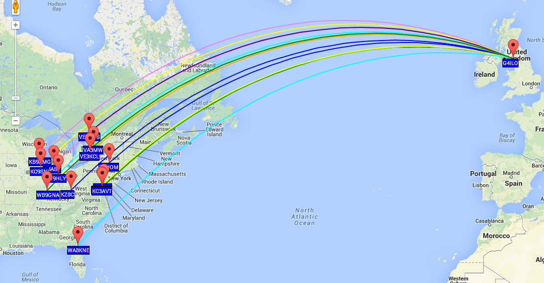 |
| WSPR spots on 10m band at G4ILO |
Interference to 10m WSPR
Take a look at this diabolical interference on the 10m WSPR frequency.
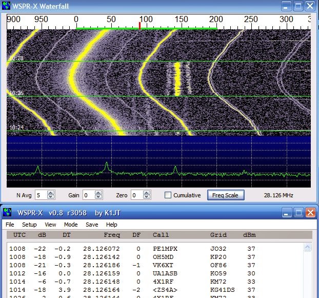
Fortunately it doesn’t seem to affect decoding too much. The PSK31 sub band is free of it too.


