Posts Tagged ‘WSPR’
 Datamode Interface built
To transmit and receive digital/data modes you need to connect the radio audio in/out to the computers sound card in/out, the computer then runs the necessary software to encode/decode the signals. I want to try out WSPR, PSK, JT65 and some SSTV for starters I have spent too long just receiving and decoding...
There are a number of inexpensive commercial interfaces available, but many of them use the same basic design originally intended for eQSO/Echolink operation. I nearly succumbed but I had built an eQSO interface many years ago when using PMR446 and had most of the parts to build another.
I nearly took the easy route and got a commercial one since connecting up some home built circuitry to a £20 hand held is slightly less daunting than plugging it into an expensive rig! My original interface has been modified and reused over the years and was a bit of a mess, but being brave I decided I could tidy it up and I couldn't really damage anything if I took my time... actually the truth was I discovered I didn't have the necessary optocoupler IC so couldn't build a new one just yet...
A simple internet search for digital/data mode interfaces will bring up a great deal of information, schematics and ideas for home brew solutions. The basics can be found here for example.
The simplest form of interface is just a simple direct lead with the transmitter operating in VOX mode. However levels can be a problem as the line/speaker output from a computer can be too high for a transmitters microphone input. Also connecting a radio to a computer directly can lead to problems with ground loops and interference.
The computer can be made to control the Push-To-Talk (PTT) on the transmitter using a serial port with the software controlling one of the handshake lines (RTS/DTR) Some data mode software support CAT to allow control of the PTT as well as tuning the transmitter, but the serial port method is more universal.
The preferred interface, and the one I had built isolates the computer from the radio by using two audio transformers and an optocoupler. There is no direct connection between the two devices so keeps interference to a minimum.
I could have used the microphone and speaker output on the radio, but the FT-857D has a convenient data connector on the back. This is a 6-pin DIN socket as used by older (PS/2) computer keyboards/mice. Note the diagram shown in the FT-857D manual (as below) is the view as you look at the socket.
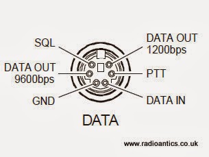 |
| FT-857D Data connector as in the manual |
Like many people I initially thought I could cut a lead off a mouse/keyboard and repurpose it, however I discovered most only use four wires and they don't use the necessary pins! You might be lucky especially with older keyboards or alternatively if you have an old keyboard extender cable they usually have all six wires present. Alternatively the plugs are readily available from the likes of CPC/Farnell.
I had a hunt around in a junk box and located a suitable keyboard extender cable. I chopped off the useless end and metered out the pins to identify the appropriate wires. Remember when looking at the plug the pins are swapped left-to-right compared to the diagram which is the socket view.
Well here is the insides of the interface.. and as you can see I completely failed to tidy it up! Not my best work, but I did put it in a new box and I did tape up all those unused wires!
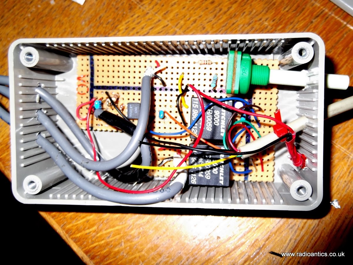 |
| The messy internals of the interface |
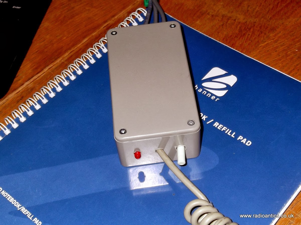 |
| It looks better with the lid on.. |
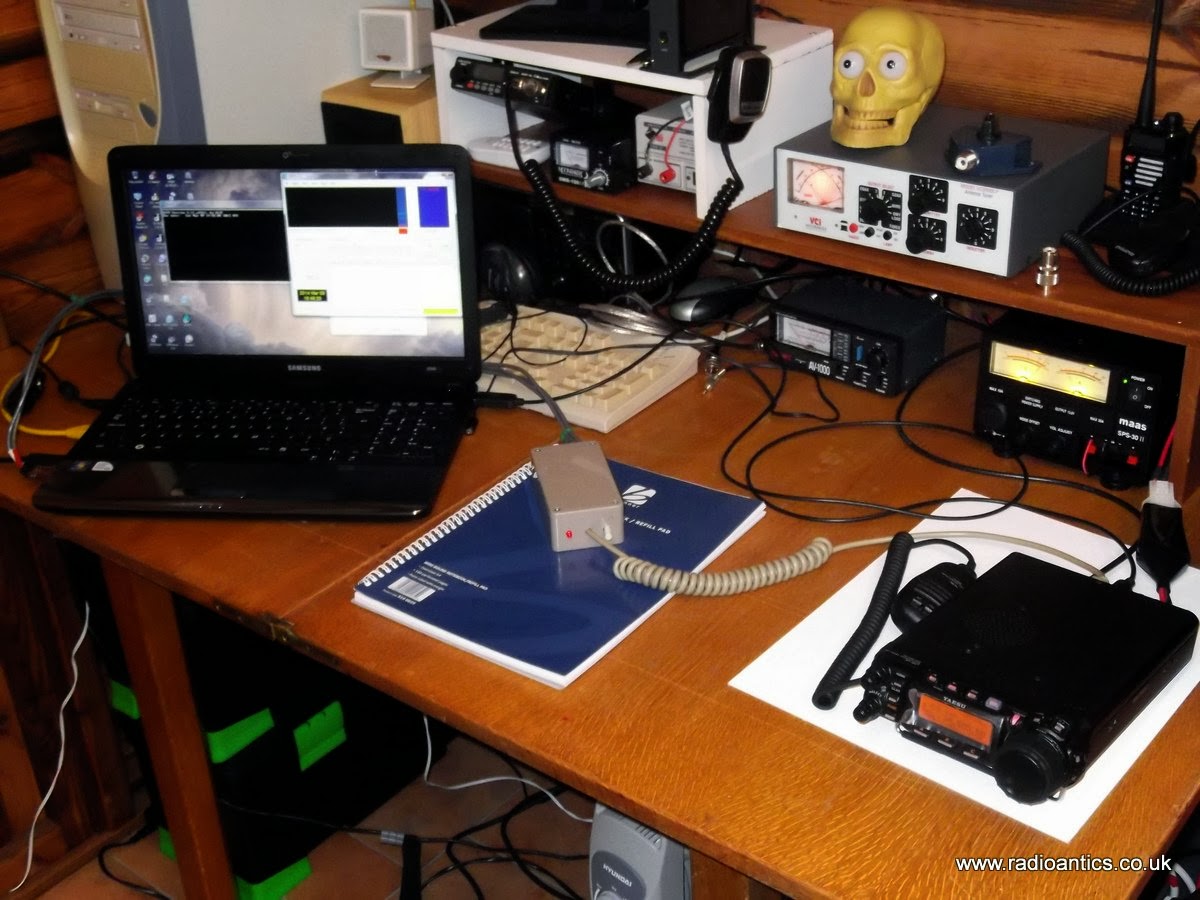 |
| Computer, radio and interface |
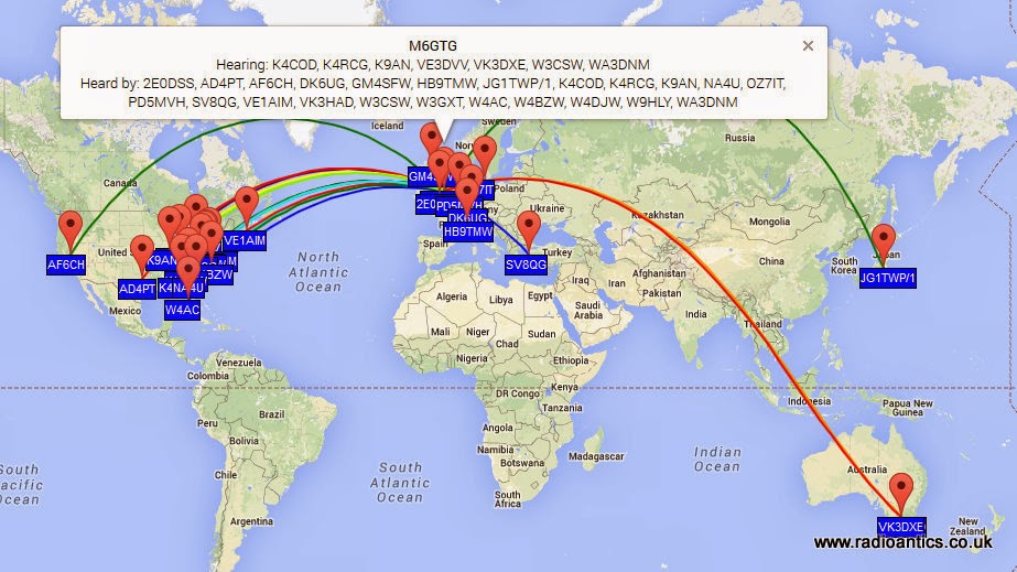
It was straight forward setting up WSPR to use a combination of CAT for tuning and the RTS PTT control and soon had some encouraging results, in fact these are some of the spots of my 5W signal on 10m/20m and 30m, I was grinning from ear to ear!
 |
| 10M Spots |
 |
| 20M Spots |
 | |
| 30M Spots |
Looking forward to spending some more time experimenting with the data modes.
Cheap GPS module
Most GPS devices have a limit on the altitude they work at, normally 60,000 feet or less. This is a legacy of the now defunct CoCom (Coordinating Committee for Multilateral Export Controls) restrictions. For my HAB project this restriction needs to be disabled and the GPS must be switched into 'flight mode' In the HAB community the favoured devices are made by U-BLOX
Therefore when I was sourcing a GPS I had search specifically for a inexpensive device using a U-BLOX.
 s s |
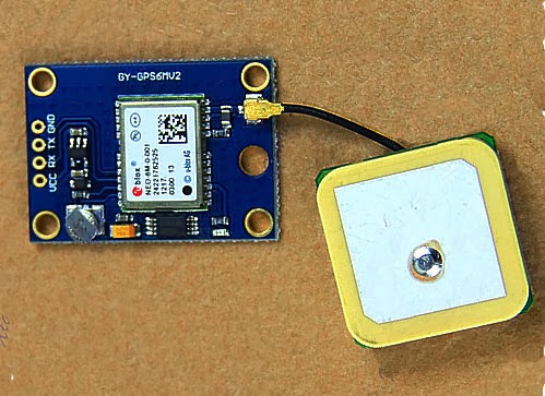
| The GY-GPS6MV2 as supplied |
It is also available from domestic suppliers but often at a much more inflated price, but you don't have to wait several weeks for them to be delivered.
There are many other GPS modules available but this module seems to be one of the cheapest available. it is often listed as a NEO6MV2 GPS Module Aircraft Flight Controller.
The module consists of a small PCB 25mm x 35 mm size with a separate ceramic antenna connected by a small lead which is 25mm x 25mm in size. The Antenna is quite heavy and isn't suited to Pico HAB payloads but for other uses is more than satisfactory.
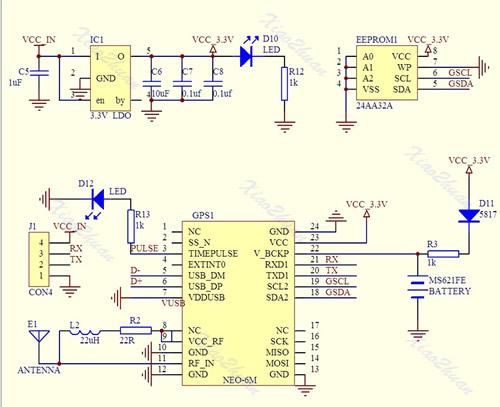
On the board is a small button-cell battery to provide backup to the GPS chip and a small EEPROM connected to the GPS chip which I believe can store configuration(s). I haven't used it myself just using the module in it's default set up at the moment. For a schematic click here
The board has four connectors VCC, GND, TX (Transmit) and RX (Receive) and can be powered by the 5V supply on Arduino boards since it has a small regulator to provide the 3.3V needed.
In most projects all that is required is data out of the GPS. The GPS TX (data out) being connected directly to the microcontrollers RX (data in) The (0V and 3.3V) level shift of the signal is compatible with the TTL input of the microcontroller.
The GPS by default will start up and output standard NMEA sentences at 9600 Baud, until GPS position lock is achieved the NMEA sentences won't have a long/lat location. The module also has an LED which will start flashing once a lock is achieved.
There is no direct connection for the highly accurate 1PPS (pulse per second) signal that can be used for frequency calibration, but the flashing LED is driven by pin 3 of the GPS module which is the 1PPS (pulse per second) signal required.
The 1PSS signal, like the TX is either 0V and 3.3V, in order to use it a small lead will need to be soldered onto the board, either directly onto Pin3 of the GPS chip, or alternatively on to the small current limiting resistor used by the LED, as indicated below.
 |
| Showing the GPS 1pps points |
Ultimate3 QRSS Beacon kit built!
My current licence restrictions prevent me using anything home-brew for transmitting except for commercial kits. So I ordered an Ultimate3 QRSS beacon kit from Hans Summers (G0UPL) thinking that it would be okay. I subsequently learned that any commercially available kit must satisfy IR 2028 which is all a bit vague and unclear but sadly I don't believe this particular kit does.
All was not lost, building this kit should more than satisfy one of the practical assessments of the intermediate examination, which will get me around this problem.
The Ultimate3 kit is extremely popular and so I had to wait a little for delivery and it arrived on Friday. After the last few weekends of non-radio activities I had planned to get my antennas backup and do some proper operating. Like many people I had been forced to take everything down due to the barrage of storms and high winds the UK has been experiencing recently.
 |
| A tidy workbench |
Saturday saw no let up in the wind, so I decided to spend a few hours building the kit instead.
The instructions were extremely clear and straight forward and soon had it built up, though it is high time I invested in new soldering station. I have a basic Antex 25W iron. I cannot remember exactly when I brought it but it is well over 10 years ago. It was more than adequate to build this kit and for soldering connectors but I could do with something adjustable and more comfortable.
 |
| Taking shape |
I also made the mistake of not scraping the enamel off the toroid wire and tried the heat it and bubble it off method, except I think my iron just isn't hot enough so ended up using a piece of wire wool to remove the enamel.
Lessons learned I soon had the other three toroids correctly wound and wire prepared for the low-pass filter board.
 |
| Close up of the LPF |
 |
| All built |
 |
| It works! |
 |
| Setting it up |
Pressing the button I occasionally got some random characters and a flashing cursor! I de-soldered the GPS and still nothing. I suspected the display was faulty but trying it on the HAB prototype board confirmed it was okay. I checked the display connector continuity and everything appeared okay.
Out with the oscilloscope I started probing, everything checked out. Crystal was oscillating and data pulses on the display control lines. Then I checked the supply pin on the display and it was only reading 4.1V, this under-voltage would explain the odd display behaviour.
PSU output was 5V, micro-controller was 5V, DDS module had 5V. All very puzzling till I removed the DDS module and spotted a discoloured track on the PCB, touching it with a screwdriver and the lacquer fell away revealing a tell tale scorch mark, somehow I had made a nice resistor!
 |
| Burnt track to right of micro-controller |
What caused it? Checking the de-soldered GPS connecting wire I spotted a stray single strand of wire on the ground wire. I suspect this must have shorted to the adjacent 5V line and since I was using a nice beefy ex-PC PSU as a bench supply it had popped the track without the hint of a flicker. The GPS has been rewired properly and is working nicely, now to connect a dummy load and experiment some more.
Sunday was a lovely day, wind dropped so antennas have been put back up and I took the opportunity to tidy up the installation a bit. I also dug out an old fibreglass pole to put the M0CVO HW-20HP back up. I didn't get to do any operating in the end as by the time I had done this and made up a couple of decent patch leads it was time for roast beef and all the trimmings and an evening in front of the TV.
 |
| The HW-20HP back up |
Ultimate QRSS kits

I’m a great fan of Hans Summers (G0UPL) and his effort in launching kits for various slow speed modes. In fact I have all three generations of the Ultimate QRSS kits up and running. That includes the original single-band kit (30 m in my case, bottom in picture), as well as number 2 and 3, the multi-band kits.
The latest version, in the middle of the picture, has a nicer two line display, and it can also be fitted with a relay board. It makes it possible to jump between up to 6 different bands.
I have used them exclusively in the WSPR mode so far. For time synchronization with the first and last version I have used an EM-406 GPS module which also provides the required pulse-per-second output. My Ultimate 2 has a too early software revision to work with the GPS, so it is on my list for a firmware upgrade.
I have a lot more experimentation to do before I know these kits and their capabilities, but I have at least gotten some experience with how far 150 mW of WSPR can take you, and that was to Australia on 30 m in my case. This is really amazing.
I would recommend the latest kit to anyone who is interested in experimentation with digital modes and who wants to compare e.g. antennas or just observe how propagation varies. The price is reasonable also, starting at GBP £17.50.
The challenge for me has been to find suitable enclosures for the two last kits. I hope to be able to make something from plexiglass for the last one. But I am still looking for that great idea for how to do that.
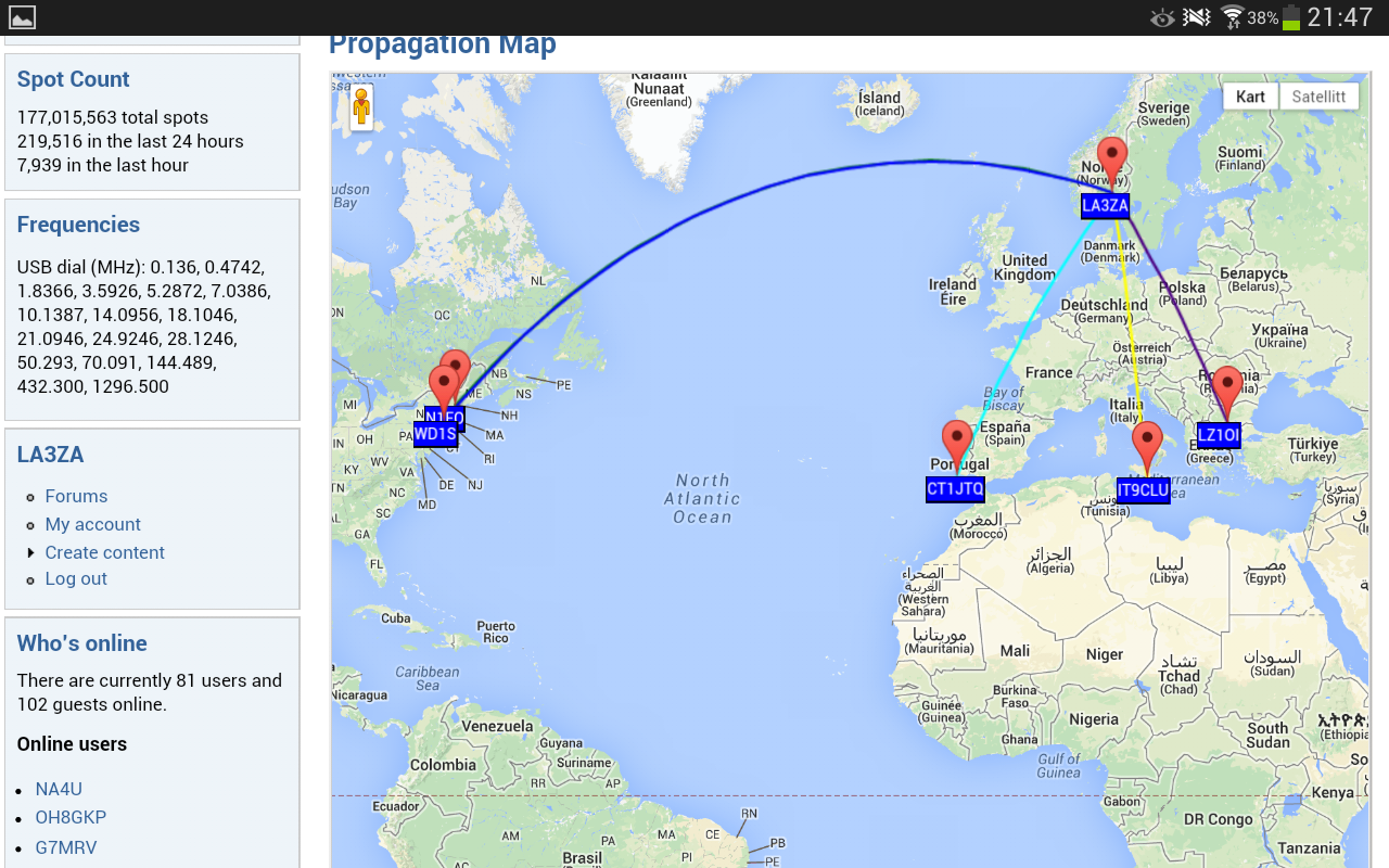
The last 24 hours on 10 m with a horizontal loop antenna, 80 m long, has caused my tiny signal to be decoded in the US several times as shown below.
See also “My first 24 hours on WSPR” and the G0UPL pages.
Across the pond on 10m with 200mW
WSPR never loses its ability to astound. Today I’ve been WSPRing on 10m, still with 0.2W. My signal was decoded by 5 different Stateside stations.
| Timestamp | Call | MHz | SNR | Drift | Grid | Pwr | Reporter | RGrid | km | az |
|---|---|---|---|---|---|---|---|---|---|---|
| 2014-01-18 14:26 | G4ILO | 28.126105 | -25 | 0 | IO84hp | 0.02 | KZ8C | EM88pm | 5973 | 287 |
| 2014-01-18 14:36 | G4ILO | 28.126145 | -22 | 1 | IO84hp | 0.02 | KB9PVH | EN53oi | 5959 | 296 |
| 2014-01-18 14:44 | G4ILO | 28.126131 | -16 | 0 | IO84hp | 0.02 | VE3SWS | FN06ge | 5201 | 293 |
| 2014-01-18 15:18 | G4ILO | 28.126107 | -9 | 0 | IO84hp | 0.02 | N2NOM | FN22bg | 5267 | 286 |
| 2014-01-18 15:38 | G4ILO | 28.126104 | -23 | 0 | IO84hp | 0.02 | K9AN | EN50wc | 6175 | 293 |
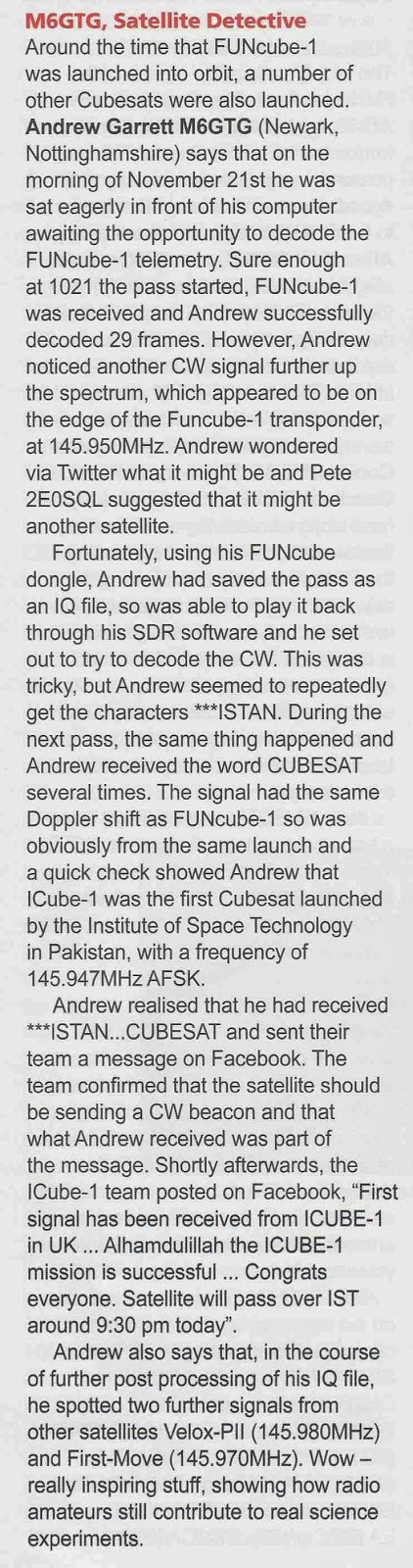
FUNCube Decode Issues
I also had a small write up in Tim Kirby's (G4VXE) VHF/UHF section of the February issue of Practical Wireless about my I-Cube1 reception which I have mentioned on here before.
I haven't progressed very far with my Arduino projects. There has been a set back in the plans to build and use an Ultimate3 QRSS kit. I had incorrectly assumed as it was a kit being sold commercially that it would satisfy my foundation conditions. However I have been advised that Foundation license holders may use radio equipment constructed using commercially available kits which satisfy IR 2028 which is all a bit vague and woolly, but I don't believe this particular kit does.
There is a simple solution, I will just have to take my intermediate assessment and exam at the first opportunity!
I have been doing a little WSPR spotting, getting some nice spots.

Over the Christmas/New Year period I have neglected the FUNCube-1(A073) satellite and was slipping down the telemetry upload rankings, sad I know!
Now I have got back the upstairs 'shack' I set up my original FUNCube Dongle on the laptop running the dashboard application continually to capture/decode the telemetry using the loft mounted discone. I took the opportunity to upgrade to the latest version 8.14 of the dashboard software, however something was amiss when checking the statistics I was only adding the odd frame here and there, sometimes not making a single decode during the high power daylight passes.
I switched back over to the newer FUNCube Dongle PRO+ running my main PC, which I had also updated to the version 8.14 dashboard and saw the same behaviour, rather than getting daylight decodes of 30+ frames I was just getting the odd 1 or 2.
My first thought it was an antenna or interference issue, but checking the SDR waterfall the signal is still very strong with little QRM. Suspecting a software issue introduced by the update I checked the FUNCube forum and found a thread which appeared to confirm my suspicions.
I have a number of discussions on twitter with various people including David Johnson (G4DPZ) an AMSAT-UK Committee Member and one of the developers of the FUNcube ground segment. David kindly performed an analysis of one of the passes yesterday where I managed just 2 frames, and from the results it does appear to be an issue at this end, rather than issue with the spacecraft.
I have uninstalled v8.14 and put back on an earlier version of the dashboard (v8.09) and thanks to a windows update last night have also performed a full reboot!
There was a good pass this morning at 62 degrees maximum elevation (to the east), followed by a lower pass at 22 degrees elevation (to the west so not so good) and it seems things have improved managing 68 and 17 frames respectively. So could this be an issue with the latest dashboard?
If anyone has suffered similar performance fall-off, or indeed not suffered any issues then please add some feedback to the FUNCube forum.
My copy of Radcom arrived but didn't have much time to read it..
 |
| The culprit! ;-) |
More WSPR with 20mW
I’ve been WSPRing on 30m today, still with a power of 0.2W. I think WSPR is more interesting when you use low power: it’s always interesting to see how far you can get.
20mW is not the lowest power you can use, though, it’s just the lowest power the K3 will comfortably produce. (You can set the output power to 0.0W but I’m not sure how accurately the rig will maintain the power at such a low level – something to check.
Today my 0,02W into the MFJ magnetic loop in my attic was received by 30 different stations. Here’s the list:
| Timestamp | Call | MHz | SNR | Drift | Grid | Pwr | Reporter | RGrid | km | az |
|---|---|---|---|---|---|---|---|---|---|---|
| 2014-01-13 11:52 | G4ILO | 10.140243 | -11 | 0 | IO84hp | 0.02 | ON7KO | JO21ce | 637 | 124 |
| 2014-01-13 11:52 | G4ILO | 10.140209 | -23 | 0 | IO84hp | 0.02 | DL8HAF/P | JO53dm | 899 | 92 |
| 2014-01-13 12:32 | G4ILO | 10.140206 | -26 | 0 | IO84hp | 0.02 | DK6UG | JN49cm | 973 | 121 |
| 2014-01-13 12:54 | G4ILO | 10.140217 | -22 | 0 | IO84hp | 0.02 | DC5EO | JO31ed | 760 | 117 |
| 2014-01-13 12:54 | G4ILO | 10.140210 | -18 | 0 | IO84hp | 0.02 | G8CRB | JO02bf | 355 | 138 |
| 2014-01-13 13:18 | G4ILO | 10.140195 | -19 | 1 | IO84hp | 0.02 | G0GSJ | IO84jc | 61 | 170 |
| 2014-01-13 14:20 | G4ILO | 10.140199 | -19 | 0 | IO84hp | 0.02 | G4ILR | JO02pp | 379 | 124 |
| 2014-01-13 14:20 | G4ILO | 10.140224 | -29 | 0 | IO84hp | 0.02 | M0BLP | JO02ad | 359 | 139 |
| 2014-01-13 14:30 | G4ILO | 10.140210 | -20 | 0 | IO84hp | 0.02 | OH8GKP | KP24rt | 1945 | 43 |
| 2014-01-13 14:30 | G4ILO | 10.140203 | -19 | 0 | IO84hp | 0.02 | GM4SFW | IO77sn | 331 | 349 |
| 2014-01-13 14:30 | G4ILO | 10.140199 | -11 | 2 | IO84hp | 0.02 | OH3HTI | KP21ag | 1760 | 54 |
| 2014-01-13 14:30 | G4ILO | 10.140182 | -13 | 0 | IO84hp | 0.02 | LA5GOA | JO29oi | 737 | 41 |
| 2014-01-13 14:38 | G4ILO | 10.140197 | -23 | 0 | IO84hp | 0.02 | OZ7IT | JO65df | 1001 | 80 |
| 2014-01-13 14:38 | G4ILO | 10.140194 | -13 | 0 | IO84hp | 0.02 | SA6BSS | JO68 | 1084 | 60 |
| 2014-01-13 14:48 | G4ILO | 10.140189 | -21 | 0 | IO84hp | 0.02 | SM6WZI | JO67mp | 1067 | 65 |
| 2014-01-13 14:56 | G4ILO | 10.140208 | -21 | 0 | IO84hp | 0.02 | DC8SE | JN48xi | 1155 | 122 |
| 2014-01-13 14:56 | G4ILO | 10.140180 | -7 | 0 | IO84hp | 0.02 | ON7KB | JO21ei | 634 | 122 |
| 2014-01-13 15:04 | G4ILO | 10.140204 | -11 | 0 | IO84hp | 0.02 | DK4TJ | JO31fc | 768 | 117 |
| 2014-01-13 15:04 | G4ILO | 10.140236 | -25 | 0 | IO84hp | 0.02 | PA1GSJ | JO22da | 586 | 117 |
| 2014-01-13 15:14 | G4ILO | 10.140238 | -21 | 0 | IO84hp | 0.02 | DL1WER | JN58dd | 1189 | 122 |
| 2014-01-13 15:24 | G4ILO | 10.140195 | -13 | 0 | IO84hp | 0.02 | DL1KCQ | JO33uc | 746 | 99 |
| 2014-01-13 15:36 | G4ILO | 10.140188 | -25 | -1 | IO84hp | 0.02 | M5LMY | IO91oi | 405 | 154 |
| 2014-01-13 15:36 | G4ILO | 10.140197 | -12 | 0 | IO84hp | 0.02 | PI4THT | JO32kf | 729 | 107 |
| 2014-01-13 15:36 | G4ILO | 10.140196 | -15 | 0 | IO84hp | 0.02 | LA9JO | JP99gb | 1949 | 26 |
| 2014-01-13 15:36 | G4ILO | 10.140191 | -20 | 0 | IO84hp | 0.02 | SM0FGT | JO89xg | 1384 | 60 |
| 2014-01-13 15:36 | G4ILO | 10.140182 | -12 | 0 | IO84hp | 0.02 | LA5GOA/RX2 | JO29oi | 737 | 41 |
| 2014-01-13 15:46 | G4ILO | 10.140222 | -12 | 0 | IO84hp | 0.02 | DC0DX | JO31lk | 776 | 113 |
| 2014-01-13 15:46 | G4ILO | 10.140215 | -17 | 0 | IO84hp | 0.02 | DC4LC | JN48np | 1088 | 123 |
| 2014-01-13 16:22 | G4ILO | 10.140208 | -17 | 0 | IO84hp | 0.02 | DK4LA | JO54ae | 868 | 88 |
| 2014-01-13 16:48 | G4ILO | 10.140196 | -23 | 0 | IO84hp | 0.02 | HB9FGQ | JN36kk | 1163 | 137 |


