Posts Tagged ‘Pixie2’
 Simple interference fix for the Chinese Pixie
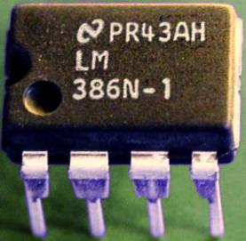
The Chinese Pixie transceiver operating at 7023 kHz has become very popular. It often costs less than 5 USD on Ebay. Like most Pixies it is susceptible to broadcast breakthrough and intermodulation. Much of this is caused by the keying circuit of the audio amplifier, the LM386. The cure is to move the muting diode from the power supply pin (no. 6) to the bypass pin (no. 7). I have described this in another blog post with title: “Using pin 7 of the LM386 to reduce BCI and add side tone to Pixie 2“.
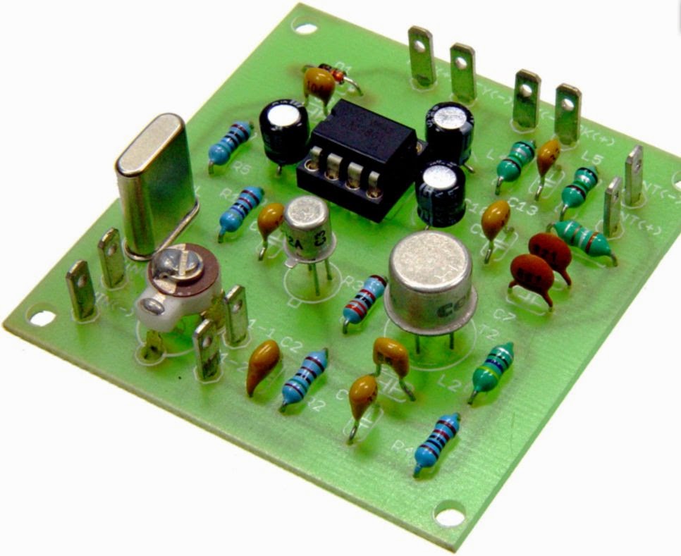
Here are two pictures that show how this can be done for the Chinese Pixie. One needs an additional resistor in the range 10 – 47 ohms. I have used 10 ohms in the picture. It replaces the old R3 of 1 k. The diode D3 is not mounted, and instead it is mounted under the PCB with the minus (denoted by the ring) connected to where D3’s minus was, and the plus side connected to pin 7 of the LM386.
 |
| R3 is indicated by the lower left arrow, and the old placement of D3 is shown with the upper arrow |
 |
| Arrow showing where D3 instead should be soldered. The minus, indicated by the ring, is to the left in the image |
Simple interference fix for the Chinese Pixie
The Chinese Pixie transceiver operating at 7023 kHz has become very popular. It often costs less than 5 USD on Ebay. Like most Pixies it is susceptible to broadcast breakthrough and intermodulation. Much of this is caused by the keying circuit of the audio amplifier, the LM386. The cure is to move the muting diode from the power supply pin (no. 6) to the bypass pin (no. 7). I have described this in another blog post with title: “Using pin 7 of the LM386 to reduce BCI and add side tone to Pixie 2“.
Here are two pictures that show how this can be done for the Chinese Pixie. One needs an additional resistor in the range 10 – 51 ohms. If you can fit it, then use the large 51 ohms resistor that come with some of the kits (I think it is meant for a dummy load). I have used 10 ohms in the picture. It replaces the old R3 of 1 k. The diode D3 is not mounted in the holes provided, and instead it is mounted under the PCB with the minus (denoted by the ring) connected to where D3’s minus was, and the plus side connected to pin 7 of the LM386.
|
| R3 is indicated by the lower left arrow, and the old placement of D3 is shown with the upper arrow |
|
| Arrow showing where D3 instead should be soldered. The minus, indicated by the ring, is to the left in the image |
The post “Simple interference fix for the Chinese Pixie” first appeared on the “LA3ZA Radio & Electronics Blog.”
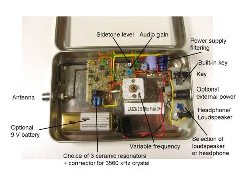
The LM386 Pixie challenge
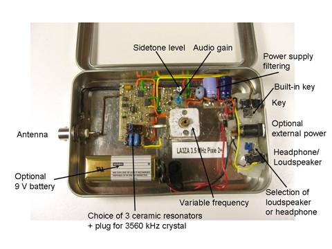
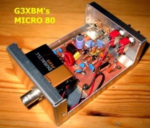
The Pixie 2 is this minimal transceiver which I and many others have played around with and had lots of fun with. My 80 m version is shown to the right, but right now it is very popular with some incredibly cheap Chinese ones on sale on Ebay and other places.
The Pixie 2 uses the versatile LM386 amplifier for its audio output. I have shown previously on this blog how its gain can be boosted and how it can implement a CW filter, and also how the muting can be improved. However, during transmission, the LM386 just sits there idle, although it can be used to amplify a sidetone from an external oscillator.
But I’m sure the old 70’s LM386 can do better than this. Despite its age, recently some pretty amazing uses of this chip have been demonstrated. It can be used as a regenerative receiver at least up to medium wave frequencies and it can also be used as an envelope detector/demodulator.
The LM386 challenge is this: Is is possible to implement a sidetone oscillator for the Pixie using only the LM386 with as few other components as possible? The output level needs to be controllable in order to make it comparable to that of the Pixie in the receiver mode.
The best data sheet for the LM386 seems to be the one for NJM386 from New Japan Radio Co. It is, as far as I know, the only one which shows the various muting circuits including the one using pin 7 which I have explored. It also shows the LM386 as an oscillator: both a sinusoidal and a square wave one.
In order for the LM386 to be useful as a sidetone oscillator, I believe that the oscillation must take place in the input circuitry. That seems to be the only way to ensure that the output doesn’t come out at a blasting full rail-to-rail swing as in the square wave oscillator example in the data sheet.
By the way, the data sheet referred to above is also the basis for the improved Spice model for the LM386 that just was developed. It came partly as a response to my complaint over how poor the present one was. Maybe the new Spice model, developed by EasyEDA, could help solve the LM386 challenge?
The LM386 Pixie challenge

The Pixie 2 is this minimal transceiver which I and many others have played around with and had lots of fun with. My 80 m version is shown below, but right now it is very popular with some incredibly cheap Chinese ones on sale on Ebay and other places.
The Pixie 2 uses the versatile LM386 amplifier for its audio output. I have shown previously on this blog how its gain can be boosted and how it can implement a CW filter, and also how the muting can be improved. However, during transmission, the LM386 just sits there idle, although it can be used to amplify a sidetone from an external oscillator.
But I’m sure the old 70’s LM386 can do better than that. Despite its age, recently some pretty amazing uses of this chip have been demonstrated. It can be used as a regenerative receiver at least up to medium wave frequencies and it can also be used as an envelope detector/demodulator.
The LM386 challenge is this: Is is possible to implement a sidetone oscillator for the Pixie using only the LM386 with as few other components as possible? The output level needs to be controllable in order to make it comparable to that of the Pixie in the receiver mode.
The best data sheet for the LM386 seems to be the one for NJM386 from New Japan Radio Co. It is, as far as I know, the only one which shows the various muting circuits including the one using pin 7 which I have explored. It also shows the LM386 as an oscillator: both a sinusoidal and a square wave one.
In order for the LM386 to be useful as a sidetone oscillator, I believe that the oscillation must take place in the input circuitry. That seems to be the only way to ensure that the output doesn’t come out at a blasting full rail-to-rail swing as in the square wave oscillator example in the data sheet.
By the way, the data sheet referred to above is also the basis for the improved Spice model for the LM386 that just was developed. It came partly as a response to my complaint over how poor the present one was. Maybe the new Spice model, developed by EasyEDA, could help solve the LM386 challenge?
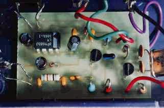
So you want to play with a Pixie?
 |
| My own surface mount version of the Pixie2 |
This page provides a guide to Pixie and related kits in a table format. These are simplistic single-band transceivers which are fun to build, yet they perform well enough to be used, although with some effort, for real contacts.
The idea of using the power amplifier transistor as a mixer seems to come from George Burt – GM3OXX – whose five transistor FOXX was described in 1983 in SPRAT. The basic design of the oscillator, PA/mixer and the simple keying has been more or less unchanged since RV3GM – Oleg Borodin – described the four transistor Micro-80 in 1992 in SPRAT. Later the Pixie 2 by WA6BOY replaced two of those transistors with the LM386 audio amplifier (QRPp 1995). Most later versions are variants of these designs.
Foxx | |
 Foxx-3 kit from Kanga, £29.95 | Incorporates a sidetone oscillator, changeover relay and low-pass filter. Different versions for the 80, 40, 30 or 20 m bands |
Micro-80 | |
 Kit from QRPme, $35.00 | Micro80D. Updated version with choice of high or low impedance headphone, polyvaricon tuning cap and board mounted connectors, 80 m. |
Pixie2 | |
 Kit from HSC Electronic Supply, $14.95 | For 80 and 40 m. Eham review |
 Kit from Kenneke, $29.95 | Includes 80 m crystal |
 Kit from QRPme, $40.00 | Lil Squall Transceiver ][. Several components and the output low pass filter are on sockets. Comes with a crystal for 40 m. |
 Ali Express Ham QRP DIY Kit Shack 40 m, $15.07 | 40 m version. Tuning pot for VXO. |
 Radi0kit, £22.00 | Enhanced Pixie2 which comes in 80, 40 and 20 m versions. Judging from the PCB layout it has an improved pin 7 muting circuit. |
What can we say to characterize these designs? One the one hand they are very simple to build and get to work. One the other hand they are also simple in the sense that they do not always perform very well. Therefore I don’t think I would recommend them to any novice ham. It takes some understanding of frequency offsets and sidebands in order to make real contacts. But many have had great fun with this minimalist transceiver which in its basic version puts out some 2-300 mW. And it encourages experimentation and modifications. Also, it should be remembered that it isn’t really necessary to get a kit, as the Pixie 2 is quite simple to build from scratch also. I did that myself.
The original designs and many variants and modifications are documented in the Pixie file document of SPRAT. There are many, many more clever modifications out there and I have my share on this blog also. To sort out and link to all the other pages is too daunting a task, so therefore I have focused on kits here. Finally I wouldn’t be surprised if the table is incomplete so I would appreciate comments if you think that something is missing.
Another Pixie
Yet another variation on the Pixie arrived by email today from Sverre Holm in Norway who has LM386 mods to reduce BCI, provide mute and add sidetone.
See http://la3za.blogspot.no/2003/04/using-pin-7-of-lm386-to-reduce-bci-and.html .
This looks a very useful mod to this simplest of circuits. Sverre also added a much wider tuning range that helps to get contacts. Low power does not seem to be the main handicap.
Pixie and Micro 80
These little QRP transceivers first made an appearance some 20 odd years ago. They are extremely simple transceivers that use the TX PA as the RX mixer to save parts.
I built a Micro 80 some years ago and my best QSO was around 300km. Biggest issue (for me) was broadcast breakthrough from strong broadcasters just above the 80m band. Variations included the Pixie 2 which added some refinements at the expense of more parts. Kits are available, but the circuits are so simple it is not work paying over the odds for these. The Micro 80 uses all discrete components whereas the Pixie and Pixie 2 use an LM386 for the RX audio.
If you build one, be prepared to fight for contacts. It is not the TX power that is the problem: it is the receiver that is the limitation.Given good conditions and little broadcast breakthrough, these rigs work.
See https://sites.google.com/site/g3xbmqrp3/hf/pixie .
The same basic schematic will work on any HF band with changes to the output filter. Watch out for chirp on the higher HF bands: don’t be tempted to try to pull the crystal too much, especially on the higher HF bands.


