Posts Tagged ‘PA0RDT’
 PAØRDT Miniwhip Shakedown
The following blog was originally published in January, 2016 but there is still much interest in this popular and well-performing antenna.
***********************************
A recent posting to the 'ndblist group' by Mike, an ardent NDB DXer in the UK (Sussex), announced the recent completion of his four-part video series describing the installation and testing of a new PAØRDT active antenna.
 If you may be contemplating the installation of an active antenna such as this, or perhaps making a start at DXing the NDB band or listening on 630m, then you might enjoy following Mike's journey as he demonstrates that living in the noisy suburbs need not keep you from enjoying the LF/MF bands. Mike includes some interesting tests involving his grounding system versus noise ingress and the results of keeping the electrical main's ground isolated (or not) from the antenna cable's ground.
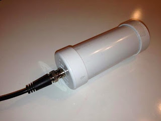
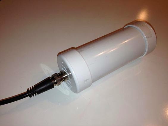
The PAØRDT active whip is available from PAØRDT himself or if you are handy with a soldering iron, you might choose to build the same antenna in your workshop. These simple yet highly effective receiving antennas are being used successfully by hundreds of listeners all over the world and for their size provide some pretty amazing performance.
Much more information on the PAØRDT e-probe antenna may be found here in a previous blog posting. To see more of Mike's videos, you can visit his interesting Youtube Channel here.
***********************************
A recent posting to the 'ndblist group' by Mike, an ardent NDB DXer in the UK (Sussex), announced the recent completion of his four-part video series describing the installation and testing of a new PAØRDT active antenna.
 If you may be contemplating the installation of an active antenna such as this, or perhaps making a start at DXing the NDB band or listening on 630m, then you might enjoy following Mike's journey as he demonstrates that living in the noisy suburbs need not keep you from enjoying the LF/MF bands. Mike includes some interesting tests involving his grounding system versus noise ingress and the results of keeping the electrical main's ground isolated (or not) from the antenna cable's ground.
 The PAØRDT active whip is available from PAØRDT himself or if you are handy with a soldering iron, you might choose to build the same antenna in your workshop. These simple yet highly effective receiving antennas are being used successfully by hundreds of listeners all over the world and for their size provide some pretty amazing performance.
Much more information on the PAØRDT e-probe antenna may be found here in a previous blog posting. To see more of Mike's videos, you can visit his interesting Youtube Channel here.
More On The PAØRDT E-Probe
 |
| Courtesy: http://www.leeszuba.com/projects/ |
Another recent reflector question about noise mitigation for active e-probe antennas brought further incite from Roelof Bakker, PAØRDT.
I found particular interest in his method of determining if the noise is being picked up by the antenna or being introduced by the feedline. As well, Roelof suggests one of the most important aspects of homebrewing ... keeping detailed notes of all tests or changes. He also suggests maintaining a healthy outlook regarding noise and rather than getting discouraged, take on the challenge of overcoming it!
Hello all,
I have been dealing with this subject for more then 10 years now and
I am pleased to pass on what I did learn so far.
The first item to look at is noise pick up on the feed line. This
can be a coax cable or a CAT5/6/7 network cable. Looking for noise
pick up on the feed line should be done without the active antenna
connected. Otherwise everything should be the same as when using the
antenna.
Ideally the antenna should be replaced by a 50 ohm termination that
can handle the power that is supplied by the DC-power supply feeding
the antenna. However, this is not necessary to achieve good results.
I am fortunate to own a PERSEUS SDR, that besides an excellent
receiver is also a nice piece of test gear. For noise pick-up
measurements I use HF-Span that changes the PERSEUS into a 0-40 MHz
spectrum analyser with a noise floor of -112 dBm. For narrow band
measurements the PERSEUS is used with Linrad, which can provide
accurate results.
Whilst looking at noise pick-up on the cable, one can unplug all
suspect devices and check if the noise is still present.
The most effective measure is grounding the shield of the coax cable
at the bottom of the mast, but I had still noise ingress of about -
100 dBm around 15 MHz. This could be solved by moving the power
supply and interface of the antenna from the operating position to
the location of the cable entry to the house. This minimises the
length of cable inside the house before the a rf-isolating
transformer used in the interface.
It is mandatory to use a separate radio earth, isolated from the
mains earth. My PC is connected to a mains outlet with a mains earth
connection, but no other equipment in the shack is using the mains
earth. This works for me.
There is also a discussion about the use of a common mode choke
versus a rf-isolating transformer. I have tried both and they both
work. However a rf-isolating transformer is much easier (and
cheaper) to build than common mode chokes with a winding of coax
cable.
In this regard, I should mention a source of interference that is
easily overlooked: receivers. It is not uncommon to own more than
one receiver and it appears that the antenna port is often far from
clean. I am using four SDR's which are fed from a balanced Norton
amplifier / four port splitter and these produce noticeable noise.
Using four rf-isolating transformers at the outputs of the splitter
eliminated the noise. My mini-whip is feeding up to 8 receivers
(hardware) via amplifiers /splitters / rf-isolating transformers
without degrading the receiver noise floor by mutual noise ingress.
The last point is about masts. A metal mast will decrease the signal
level when the antenna is mounted close to it. A short PVC extension
mast will help. The reason I am using a non-conductive mast is a
practical one as cheap and sturdy stackable camouflage net mast
sections were and are still available in western Europe. These are
ideal for either testing antennas and for permanent installations.
Metal masts can introduce problems by being resonant at a certain
frequency and receiving noise that can be transferred to the feed
line. However, checking the feed-line as described above will make
clear if this is the case or not. If there are no problems, there is
nothing against the use of a metal mast.
As every location is different, it is no use to provide an exact
recipe to solve noise problems. I believe that a systematic approach
is mandatory; take notes etc. as it is too easy to run in circles.
By all means do measure what you are doing, otherwise you will walk
in the dark for sure.
The good news is that it is still possible to build a low noise
reception system in the city and doing so can be fun! What might
also help is to change the attitude from 'it should not be there
after all' to 'what can I do about it!'
Best regards and 73,
Roelof Bakker, pa0rdt
If you're thinking about having a listen on LF or on 630m, the e-probe antenna can be a very effective solution .... and it takes up very little space. The finer details regarding the PAØRDT active antenna may be found here and here. All previous blog postings related to this topic may be found here.
Is Your Miniwhip Too High?
 |
| The Mini-Whip at University of Twente's (Netherlands) Remote Receiver |
A recent posting to Yahoo's ndblist Group described an interesting experiment by Dirk Claessens regarding the signal-to-noise ratio (SNR) versus height of his PAØRDT active whip. Dirk's tests were posted on Yahoo's Navtex DXing Group where some further interesting discussion seemed to confirm his findings.
Here is what Dirk discovered, backed-up with his graph data, clearly pointing to the 'ideal height' at his location ... and probably yours as well.
Hi all,
You may recall that to get rid of a source of QRM, my whip is now hanging from a rope-and-pulley system, about 5 .5 mtr from the house, at a height of 7 meter agl.
As the height of the whip can easily be changed, this is an ideal situation to test the behaviour of the whip wrt noise levels, optimal height etc..
I had done this test before some 4 years ago, but not very precise. Time to do it again, and documenting it.
What I also wanted to check, is if there were any noise sources of the own house possibly reaching the whip.
(how far does the "noise bubble" go in function of the height?)
The Perseus was tuned to 549 KHz Deutschlandfunk Nordkirchen, the station closest to 518.
2 markers were set, one to the signal, and a reference marker in a quiet spot nearby on 543 KHz, to get a reading for the noise floor.
The whip was then lowered in "1 meter each minute" steps, readings were taken and written to the marker file.
First the absolute values were plotted.
Note that: blue = noise floor, red = signal, and that the left and right axis scales have identical spans of 19dB, but are shifted, in order to get a compact graph.
We see that for a delta height of 6 meters:
-the noise floor goes up ~8dB, or 8/6 = 1.3 dB/m, almost linearly.
-the signal goes up ~14 dB, or 14/6 = 2.3 dB/m, clearly curved and showing a maximum at ~5..7 m.
The continuous lines are polynomic (2nd degree) regression lines.
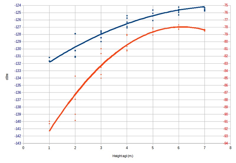
The noise on the measurement values seems to increase with decreasing height. Was this caused by my body standing under the whip, and near to the whip for the lowest measurements??
What really matters of course, is the signal over noise value, this is plotted below:
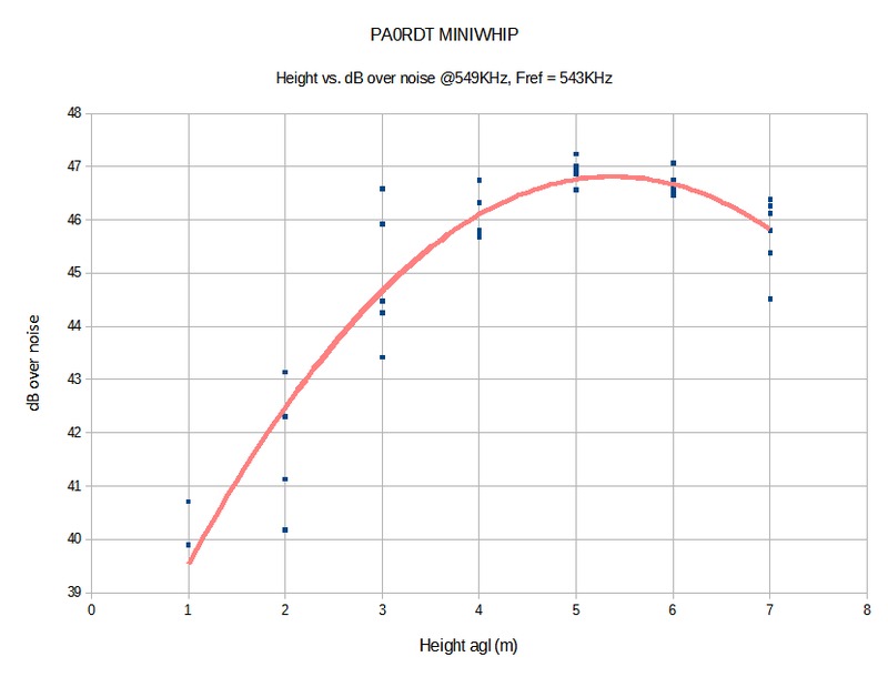
-Within a narrow 1 dB band, the curve shows a clear optimum in the region of 4..7 m agl, a familiar value often given as optimal by Roelof.
-The measurement was performed during the day and thus with ground wave propagation. As the whip is truly omnidirectional, I cannot see a reason why the behaviour would be different at low angle DX signals.
- At 5.5 meter from the house, the whip seems to be outside of the "noise bubble"
and later, following discussion:
I have just checked the noise floor again at 518 (with no signal present)
Perseus set to 125 kS/s, Span/RBW 25/30.5
Shield grounded: -125 dBm
Not grounded: -110 dBm
That's a whopping 15 dB difference!
I have also buried the coax ~20cm deep from the grounding point to where it enters the house.
The ideal height was also that recommended by Roelof, PAØRDT, originally and points out that one of antenna-building's most sacred commandments ... "the higher the better", is not always true!
I have often recommended this simple antenna for those looking for a very effective yet low-footprint receiving antenna for use on the LF and MF bands.
Much more information about Roelof's popular miniwhip may be found in previous blog discussions here.
PAØRDT Miniwhip Shakedown Continues
Those of you that have been following the recent set of four YouTube videos posted in my recent PAØRDT Miniwhip Shakedown blog, regarding the care and feeding of the PAØRDT active e-probe antenna, may be interested in a fifth video in the series, posted by Mike in the U.K.
PAØRDT's recent modification of the isolating transformer, in the miniwhip coupling unit, provides much better immunity to common mode noise-coupling in the HF bands. Mike shows the installation and operation of the new unit along with some additional grounding out at the antenna.
Those of you that are looking for a possible solution to relatively good reception on LF or on the 630m band, might find the answer with a carefully thought out installation such as the one shown in Mike's video series.
Although living in the suburbs often means dealing with a lot of noise, particularly on LF / MF, Mike's system shows that excellent low noise reception is indeed possible. It is important to 'probe' your backyard with the antenna itself in order to find the quietest location for installation.
More information on the PAØRDT miniwhip and other low-noise LF / MF antennas may be found in previous blogs here.
PAØRDT E-Probe Improved VLF Noise Performance
|
| courtesy: http://www.leeszuba.com/projects/ |
A recent blog posting of four videos showing the installation of a new (Roelof-made) PAØRDT active E-probe antenna revealed that there appeared to be a difference between his earlier model and his latest. It was noticed that the noise ingression levels were different between them, with one showing less noise on LF than on HF, while the other one behaved just the opposite. The newer PFU has the antenna ground isolated from the receiver's ground while the older one does not. Noise coupling, with the new one was higher on HF and lower on LF, which was just the opposite of what was noted with the older unit with its un-isolated ground ... overall LF performance over the newer system was deemed to be better as seen in the final video here.
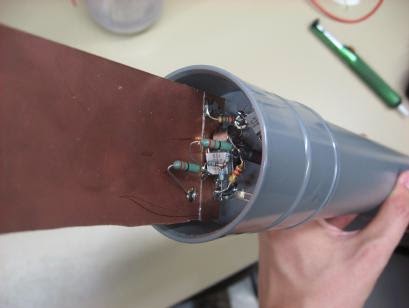
The only difference seemed to be in the coupling isolation transformer, used in the power feed unit (PFU), likely similar to the one shown at the bottom of this page.
Roleof's transformers are wound on a Magnetics 0W40705TC toroid, whose high mu ferrite has an Al value of ~8350. I mentioned to Roelof that is seemed unusual that the noise levels would be greater on HF than on LF, with the new transformer, as usually it's the other way around when it comes to noise. The changes noted in the video lead to further transformer testing by Roelof, who indicated :
The isolating transformer consists of two bifilar windings on a high mu core. My guess is that the interwinding capacitance spoils the isolation at HF. I have just tested an isolating transformer with two separate windings opposite each other on the tiny core. Sure enough, this solves the feedthrough at HF and VLF performance is not impaired at all.
I have never given this a second thought as I believed it was specific for my location. Never too old to learn!
Further testing indicated:
I have evaluated both transformer types on my spectrum analyser and found the following.
The current transformer with a twisted bifilar winding is a
transmission line transformer. In a 50 ohm system, it covers 4 kHz (!) to 200 MHz at -3dB. Which is very good.
The new one, using the same core and separate windings is an other
story. It covers just 4 kHz to 8 MHz at -3dB. At 30 MHz the loss is
13 dB. So, excellent for VLF / LF/ MF, it won't do for upper HF.
I will try other core material and see if a feasible compromise is
possible.
To be continued.
further...
I first tried a FT-37-43 toroid with 10 turns for each winding.
This core is suitable for higher frequencies and I expected it to
work better than my high mu (8300) cores.
Nope, it was far worse and at 30 MHz the loss was already > 20 dB.
I reverted back to my magical cores and reduced the number of turns
to 3. This yielded a nice bandwidth (-3dB)from 50 kHz to 50 MHz.
Used in the mini-whip interface, there is no more a difference
between shared grounds and isolated grounds on either VLF / LF or
HF.
Though the lower -3dB point is at 50 kHz, I still have excellent
reception of the Russian Alpha stations between 10 and 15 kHz.
It looks like this transformer is an excellent compromise for this
purpose.
I have often found that in practice, high mu cores are excellent for
wideband transmission line transformers. They are good for
traditional rf transformers as well!
and:
I just have tested a binocular core, the BN-73-202, available from
W8DIZ.
With two windings of two turns each of insulated hook up wire (to
keep interwinding capacitance low), gives a transformer from 80 kHz
to over 100 MHz. In practice reception down to 10 kHz is still
excellent.
There is no difference between isolated or common grounds either.
The coupling with this binocular core is a little better than with a
toroid. At LF / MW, I don't find any loss at all.
The FT-50-75 will do fine with two windings of 4 turns each.
I have some FT-50-77 cores at hand and will see how they work out.
I am surprised at the wide bandwidth that can be achieved.
and:
I have been testing a FT-50-77 ferrite toroid for use as wideband
isolation transformer.
Three turns on the Magnetics (aka magical) cores, give an inductance
of 60 uH. Used as a wideband Isolation transformer, the -3dB
bandwidth ranges from 80 kHz to 50 MHz.
For about the same inductance, the FT-50-77 core needs 6 windings.
Used as wideband isolation transformer, the lower - 3dB point is 100
kHz, the upper is 12 MHz. At 30 MHz the loss is already 8.5 dB.
Though not suitable as wideband isolating transformer, it still can
be used for the range 100 kHz - 3 MHz.
It looks that for good wideband performance the Al value must be >
5000 and the number of turns should be =< 3.
Interesting stuff and the best thing is that it has really lowered
my noise floor!
A summary posting to the RSGB's LF reflector indicates that the new transformer scheme is providing quieter VLF reception and good performance up to 200MHz
For years, I have been using a rf - isolating transformer to
separate antenna and receiver ground.
This is a home made transmission line transformer, consisting of 11
bifilar turns on a small high mu toroid (AL=8300). The inductance is
1.2 mH. The measured -3dB bandwidth in a 50 ohm system covers 4 kHz
- 200 MHz.
It appeared that the isolation was not perfect, due to the
inter-winding capacitance. I have made a new transformer on the same
core with two windings of each tree turns. The windings are opposite
each other on the core. The bandwidth is now 45 kHz - 50 MHz. The
loss is 1.3 dB.
Despite the raise in the lower -3dB point, reception at VLF is much
improved due to lower noise ingress. See attachment.
The screen runs from 1 kHz - 13 kHz. At the right hand the dashes
from the Russian Alpha system can be seen. The white band is with
common ground. Harmonics of the 50 Hz mains can be easily spotted.
In reality the picture will be better,as the sensitivity of the
PERSEUS drops considerable below 10 kHz.
The level of interference on 380 kHz caused by a plasma TV in the
neighbourhood is also much reduced.

An excellent video demonstrating the dramatic effects of isolating the ground in the e-probe antenna system on LF was posted today by PY3CRX. Marcus used the Magnetics hi-mu core with 5 + 5 turns (~ 390 + 390 uh).
For those not having access to the Magnetics material, it looks like the BN-73-202 binocular core is a good performer, from 10kHz - 100MHz. The FT-75 and 77 material also fair well but with differing bandwidths. Cores are available from Amidon as well as from W8DIZ's Kits & Parts.
PAØRDT Miniwhip Shakedown
A recent posting to Yahoo's 'NDB List Group' by Mike, an ardent NDB DXer in the UK (Sussex), announced the recent completion of his four-part video series describing the installation and testing of a new PAØRDT active antenna.
If you may be contemplating the installation of an active antenna such as this, or perhaps making a start at DXing the NDB band or listening on 630m, then you might enjoy following Mike's journey as he demonstrates that living in the noisy suburbs need not keep you from enjoying the LF/MF bands. Mike includes some interesting tests involving his grounding system versus noise ingress and the results of keeping the electrical main's ground isolated (or not) from the antenna cable's ground.
The PAØRDT active whip is available from PAØRDT himself or if you are handy with a soldering iron, you might choose to build the same antenna in your workshop. These simple yet highly effective receiving antennas are being used successfully by hundreds of listeners all over the world and for their size provide some pretty amazing performance.
Much more information on the PAØRDT e-probe antenna may be found here in a previous blog posting. To see more of Mike's videos, you can visit his interesting Youtube Channel here.


