Posts Tagged ‘GW3UEP’
 GW3UEP 630m Transmitter Tweaks
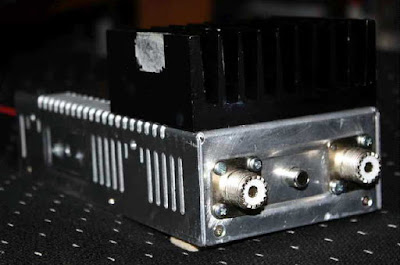 |
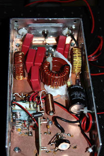
| DF8UO's GW3UEP 630m Tx |
Hi Steve,
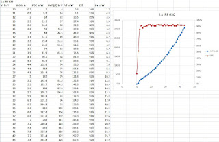
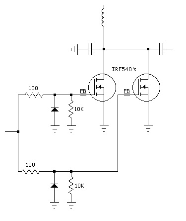
I have seen on your Website, that you are also a MF/LF fan and builder of GW3UEP QTX. I build the version with 2 IRF540 as you proposed and the same version with 2 IRF630. As I bought some time ago a PSU with can be regulated from 1V to 60V and max 10A (it is a Manson HCS 3404) I made some measurements on both version. Find attached an Excel with the measurements I made, if you are interested in.
If you use the IRF540 version you can see that if the power exceeds 100 W, the efficiency goes down, as the IRF540 is only specified for 100V.
Currently I am using the IRF630 version running at 300W without problems.
From Daniel's test data, it looks as though the IRF540's are quite happy as long as you keep the transmitter at 100W or less ... anything higher would certainly benefit from the switch to IRF630's as the high efficiency is maintained at least to the 300W level. Something at this level would no doubt benefit from higher-voltage capacitors and heavier inductors as well as a little more heatsinking, enough to shed at least 25 watts of heat between the two FETs.
Daniel drives his amplifier with an Ultimate3, followed by a 10db attenuator, a squarer and into the totem pole driver stage. His own version uses toroidal inductors rather than the original air wound coils.
A pair of GW3UEP amplifiers using IRF630's at ~40V into a small power combiner, should provide ~550W of useful output at >90% efficiency ... more than enough power to do some serious work on 630m.
 630m Resources – Part 2

Using the transverter approach offers the advantage of providing a higher-stability signal generated by the main station's transceiver oscillator system. Most of the digital modes require a higher stability than would be needed for straight CW.
If your main interest is normal speed CW, then a digital VFO, such as the one devised by GW3UEP, would do the job.
If you are content operating on 475.0 kHz, then an inexpensive 7.6MHz crystal, in a divided-down oscillator will work well, and with good enough stability for some QRSS work as my earlier "GW3UEP Transmitter In QRSS Mode" report indicated.
The other option for frequency generation is a DDS.
 |
| N3ZI DDS |
For those wanting something a bit more robust, W1VD describes a very nice high-power transmitter. His website is packed with useful circuits and ideas for both 2200m and 630m.
 |
| W1VD Dual-Band Kilowatt : http://www.w1vd.com/ |
W7IUV also describes, in great detail, his method of generating high-power on 630m. There is much to be learned from his document describing the design and operation of his unique 'linear-mode' transmitter.
 |
| W7IUV 630m TX: http://www.w7iuv.com |
Another practical way of generating moderate power, certainly enough to meet the Canadian 5W EIRP limit, is to combine two or more 100W transmitters, such as the GW3UEP transmitter. It is reasonably simple and inexpensive to combine several modules with the use of a homebrew power combiner, as previously described.
 |
| Homebrew 630m two-Port Power Combiner / VE7SL |
 GW3UEP 630m Tx Complete
I was finally able to put the finishing touches on the new GW3UEP Class-E transmitter by mounting the hardware on a small 19" panel.
Added to the panel were a 5A DC meter to monitor drain current, a keying jack and a key shorting-switch for keydown testing. This is the third version I have built using the design on Roger's page, with all three performing pretty much as advertised. It is an inexpensive, easily reproducible design.
Added to the panel were a 5A DC meter to monitor drain current, a keying jack and a key shorting-switch for keydown testing. This is the third version I have built using the design on Roger's page, with all three performing pretty much as advertised. It is an inexpensive, easily reproducible design.
I made one small change in the third version (above) by adding an additional FET in parallel with the single IRF540 thus cutting heating dissipation as described in an earlier blog. At normal CW keying speeds, no heatsinking seems needed on this particular version, when operated on 12VDC. Anything a little higher or any QRSS modes would require heatsinking. I did eventually add two small heatsinks in case I chose to run QRSS at some point.
When operated at 12-13V, the measured output power is around 25W while at 22-23V, the output is around 70W. I suspect that you could get in excess of 100W out, at higher voltages and larger heatsinking or by blowing the sink with a small fan.
The main function for the new transmitter will likely be as a semi-permanent beacon as well as for a small signal source when tuning the antenna. I may also use it in the WSPR mode with a modification to the oscillator section. One particularly nice feature with the Class-E design is that with no load at all, the current drops to almost zero, should the antenna suddenly fail.
If you live in VE7 or across the border in W7 land, please have a listen on 475.0 KHz and let me know if you can hear the "VVV" beacon over the next few days!
 Smoke Testing The GW3UEP 630m Transmitter
 |
| Drain (top) vs Gate (lower) on testbed Class-E GW3UEP TX |
I've just completed the Muppet-styled printed circuit version of my previously breadboarded GW3UEP 630m transmitter. The earlier version was built "ugly style" in order to optimize part values and measure circuit parameters.
 |
| Testbed (Ugly-Style) |
 |
| Final Version (Muppet-Style) |
Running the TX at 12.8VDC on the drain(s) at 2.3A produces an input power of 29W. The measured power out, after the LPF, is 23W into a 50 ohm load. This represents an efficiency of 80%. When run in the normal speed CW mode, the FETs run cool enough that they would probably not even need a heatsink but if run in any of the QRSS (long keydown periods) modes, would certainly benefit from heatsinking.
Running the TX at a higher voltage of 22.6VDC (on the amplifier only) yields a current of 4A for an input of 90W. Measured output power is 71W for an efficiency of 79%.
Heatsinking would be required at this power level, even for normal speed CW but the finals seem to run just slightly warm. A larger heatsink or possibly a small fan as well would be required for any QRSS CW modes.
I suspect that the efficiency could be further improved yet with very fine tweaking of the output circuit L/C network but the extra few watts gained would not be significant.
At either power level, this easy-to-build transmitter would make a great "first 630m transmitter" for anyone wanting to get started on our new band.
 630m Trans-Pacific WSPR
 |
| Courtesy: https://www.google.com/maps/ |
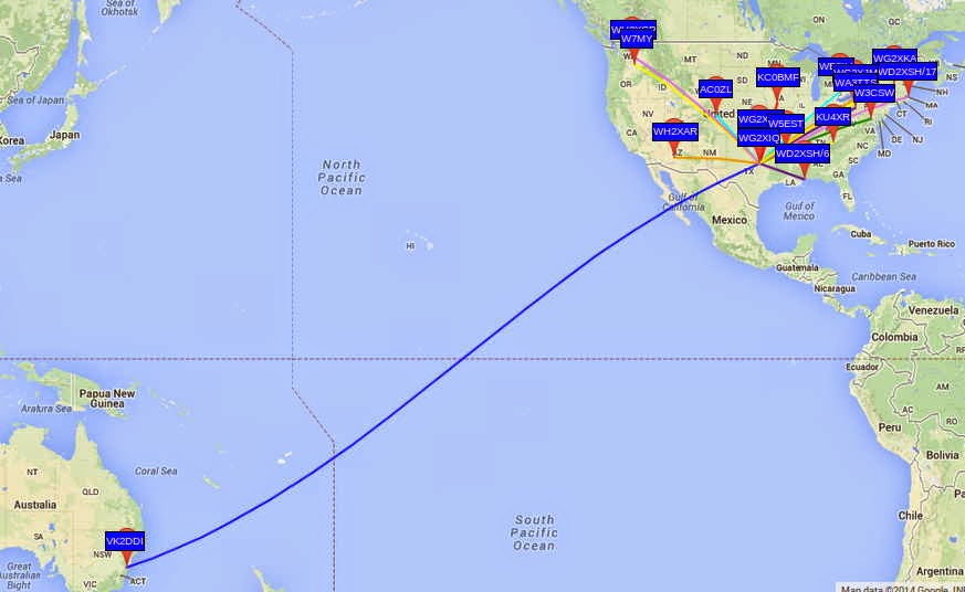
This is particularly noteworthy in view of the relatively low power used for John's beacon....around 200W. With the typical backyard antennas being used at these frequencies, efficiencies are very low and John's actual ERP is less than 5W. The transpacific reception of John's signal by VK2DDI confirms what most LF'ers already know....that small suburban lot amateur installations can have positive results on 630m without the need for huge antenna systems.
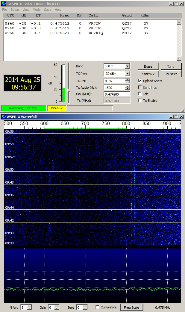
The WG2XIQ beacon was operating in the WSPR mode, which has become very popular amongst 630m experimenters as well as those just interested in listening-in. WSPR is not a QSO mode but strictly a one-way 'beacon' mode. Although two stations may each spot each other, it is not considered to be a valid two-way QSO. A check of evening WSPR activity will often reveal dozens of stations actively spotting what they are hearing.
Like most LF stations, John's is mostly homebrew.
| WG2XIQ/KB5NJD |
I'll let him describe the details:
"I have a few ways of making RF in the shack. I can do CW with a very nice waveform using the GW3UEP VFO/Driver coupled with a GW3UEP 100w amp with waveform shaping. The other way is via the MF Solutions transmit downconverter, developed by John Molnar, WA3ETD/WG2XKA. I have two of those boards, one is a backup. I use a GPSDO for the LO and use that signal to drive two parallel GW3UEP amps with max power at 125 watts each. The W1VD Ø degree hybrid combiner brings them together in phase for close to somewhere between 200 and 250 watts TPO depending on how hard I drive and how close I match the TX levels entering the combiner. I filter the output with the W1VD KW LPF that was built by Dave Robinson G4FRE (ex WW2R). I power the amps with a pair of BK Precision 30V 6Amp variable power supplies (variable current limit threshold also). Scope match is used to resonate and match the the impedance. IF Rig on 630m is typically a Yaesu FT920. These days RX antennas are the VE7SL multiturn loop or the TX vertical, both of which have their own merits depending on the conditions at the time."
| John's 630m Vertical |
"Antenna is an 80 foot asymmetric T-top marconi with 100 foot and 200 foot legs....radial system is almost 3 miles of radials connected via various busses. 26 ground rods around the property. I monitor current in the shack and sample via a Bauer current transformer from an AM BC ATU."
| 630m Radial System |
John's system does indeed work well...just last year at this time, his 630m signals were copied by KL7L near Anchorage, Alaska.
Of course, equal credit must be given to VK2DDI for having a system good enough to hear John's signal all the way down on Berry Mountain, New South Wales, Australia! It is there that David has set up a fine LF station, 500m above and overlooking the Tasman Sea...an ideal location for weak-signal LF work.
 | ||||
| VK2DDI - Berry Mountain, NSW |
 | ||
| WG2XIQ Signal As Heard in VK |
David also runs the Berry Mountain Grabber, providing other VK and ZL experimenters a handy way of checking their system progress or propagation conditions.
If you have been doing any WSPR work on HF, you might be surprised at what you can hear down on 630m, even without a dedicated antenna for that band. Surprisingly good results can often be had with a non-resonant antenna as the signal to noise ratio can often be better even though signals may sound weaker. Give it a try and spot what you hear!
If you are interested in learning how to receive WSPR, here is a nice tutorial by ZS6SGM.
Should you be interested in knowing more about obtaining a Part 5 licence to transmit on 630m, John will happily guide you through the process. He can be contacted via email or you can find him hanging-out most nights on the ON4KST kHz (2000-630m) chat page.
To keep on top of what is happening or who is on-the-air, most LF'ers rely on three sources:
- the RSGB LF Group reflector
- the Lowfer list
- the LWCA Message Board

