Posts Tagged ‘engineering’
 Vacuum tubes could revolutionize computer chips?
No, I’m fairly sure I haven’t lost my mind … that really is the right headline.
 According to a resent paper published in the American Institute of Physics, nanoscale vacuum “tubes” manufactured using conventional chip making techniques have operated at frequencies as high as .46 THz.
Dr. Meyya Meyyappan, Director at the Center for Nanotechnology at the NASA Ames Research Center, has highlighted the advantages of nanoscale vacuum devices which include resistance to hard radiation and significantly improved operating frequencies.
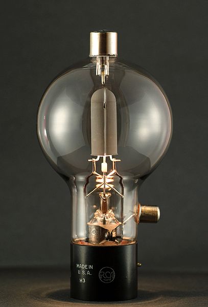
![]() The increased operating frequency comes about because of the speed at which electrons travel through different materials. The speed of electron travel through silicon is comparatively slow, through graphine it is approximately 100 times faster and through a vacuum it approaches the speed of light.
The increased operating frequency comes about because of the speed at which electrons travel through different materials. The speed of electron travel through silicon is comparatively slow, through graphine it is approximately 100 times faster and through a vacuum it approaches the speed of light.
While the cavity is not technically a vacuum it contains so few atoms of any other material, such as oxygen, it is functionally the same. This also gives the vacuum nanoscale device an advantage in space where hard radiation can disrupt an electron’s travel through silicon leading to errors or sometimes permanent failure.
Dr Meyyappan estimates that vacuum nanoscale components will run ten times faster than the best conventional silicon chips and who knows what advances the future will hold. Faster chips will aid in signal processing and more capable software defined radios.
Do you want to monitor every CW & PSK31 transmission on the 40M band at once? With a vacuum “tube” rig you may be able to!
Recent tinkerings (19 May 2012 edition)

I try not to do these “meta-posts” too often, but time has been of the essence lately and it’s been hard to find enough time to sit down and write something coherent when most of my “ham time” has been devoted to DXing or antenna work. This post covers tinkering and operating from K8GU since January (!!).
I am not at Dayton this year.
Worked 7O6T on three bands (20/17/15) on CW and also on 20-meter SSB. The only one I spent more than five minutes for was 20CW, which was during the first few days of the operation. Normally, I would have waited, but since this was in the land of pirates and AQAP, I decided to play it safe in case there was an international incident that curtailed the operation. My friend Steve, K0SR, gave me a hard time when I bragged about working them with 100 watts and a dipole. You can do that on the East Coast. He’s right. DXing and DX contesting from the Upper Midwest (aka The Black Hole) is hard.
Did not work 6O0CW (Somalia) or 9M0L (Spratly). XX9E (Macao) is doubtful since it’s a short DXpedition and I’ve only heard them once so far.

My 2011 Sweepstakes “Clean Sweep” mug arrived. Sarah banished it from the kitchen because it’s canary yellow. I think it’s hand-wash anyway, so it will continue to hold baby-proofing outlet covers and look good on the top shelf in my shack next to the liquid-crystal painted Jicamarca mug. Speaking of baby-proofing, Evan is on the move…

I built a gate that fits in the aperture of my shack desk. An unintentional feature of this is that I can still reach the keyboards through a gap at the top. It’s a little hard to send CW through there. But, it keeps curious Evan away from the jungle of wires that make up this “wireless” station.
In January, I took down my VHF antennas from the main house chimney. I had estimated the wind surface area of the chimney and determined that the wind load of the antennas increased it by 15-20%. Since I know that the guys (it was built in 1946ish, so yes, guys) who built the house didn’t do any calculations I figured that the safety factor was at least a factor of two. But, I was growing increasingly uneasy about the torque exerted by the antennas on the chimney, so I took them down.
In March, I had the opportunity to pick up (from K3AJ, who beat me by three QSOs in ARRL SS CW last year…need to be disciplined since I left 4 hours on the table) a M2 2M9SSB Yagi for two meters on great terms (per usual). This antenna is lighter and stronger than the homebrew K1FO that I had been using. I cut up the elements from the 2-meter K1FO to make Yagis (also K1FO designs) for 222 and 432 on 10-foot booms. Need to finish those and put them up.
We have another, shorter chimney on the addition that houses my hamshack. This chimney has served as the anchor for my 10-meter rotable (by the Armstrong method) dipole for a while now. Branches from a nearby tree have impinged on the rotation somewhat, but since it’s bidirectional it hasn’t been a big deal. But, I decided that this might be a good location for the new 2M9SSB, the A50-3S (3-el 6-meter Yagi), and the 10-meter dipole. I himmed and I hawed. Then, I climbed the tree and sawed. It’s a miracle I didn’t end up with poison ivy.
I upgraded the 10-meter dipole using hardware from DX Engineering so it could be mounted to a mast (old method was not mechanically sound, especially for something that would be rotated with a T2X).
A few weeks ago, I assembled and installed the whole mess…see photo at the top of the post. I’m now using a Hy-Gain T2X (purchased at Dayton in 2005—I showed up at my in-laws’ grinning ear-to-ear with the motor in one hand in the control box in the other—they still love to tell this story) instead of a CDE TR-2 rotator. The T2X can probably turn the house.
A spring wind storm dislodged the branch that supported my 80-meter wire vertical and one end of the 20-meter dipole. So, I cleaned that up last weekend. By “cleaned,” I mean I took both of those antennas down. I also took down the 160-meter TEE because one of the TEE wires was very close to the new VHF array. At this point, I was only QRV on the “Technician bands”…minus 80…40/15/10/6/2. I almost got the 160-meter wire all the way out of the tree except the rope that supported the center (TEE junction) bound up with the junction about 10 feet off the ground. So, I improvised a hot knife on a stick to cut the poly rope:

It worked great. As she should have, Sarah gave me a hard time. There are two types of people: those who watch Red Green and there are those who inspire Red Green.
Taking a wonderful brilliant hint from N4YDU, I replaced my 30-meter coax-fed dipole with a 30-meter open-wire-fed dipole. While I prefer resonant single-band antennas for contesting (clean patterns and nothing to touch when changing bands), every other kind of operation can tolerate tune-up. The open-wire-fed 30-meter dipole not only tunes well on 17 and 12 meters, it just has a slightly narrower pattern! An aside: After the 2010 ARRL 10-meter contest, I posted to the PVRC reflector that I had been running 100 watts to a dipole at 30 feet. This prompted my neighbor (who lives about 2 miles away, a neighbor for bands below 76 GHz) K3KU to pay me a visit because I had beat him in every pileup that weekend. He thought surely I was running a KW to 5 elements at 60 feet! He runs an open-wire fed 135-foot long dipole on all bands through a tuner. The pattern of that antenna looks like a sea anemone on 10 meters!
Worked D3AA on the third call on 30-meter CW last night. So, I guess that antenna is working. Also worked VP9GE on 6 meters. There’s a certain amount of satisfaction working DX with a transverter you designed (mostly) and built yourself.
I have a wicked RFI problem on 6 meters when I run the amp (150-watt Mirage brick). It’s probably RF on the power lines, although it doesn’t set off the CO detector like 40 meters does. So, it could be RF pick up on the audio wiring in my shack. In any case, need to get that worked out before the ARRL June Es contest.
Something old, something new.
Something old …
As a young boy in Australia my two favorite hangouts were my grandfather’s shed or practically anywhere that electronics were sold. The two largest electronic component retailers in my home town were Tandy (Radio Shack) and Dick Smith Electronics. They both sold kits, tools, ‘100 in 1 Labs’ and other assorted gear but Dick Smith eventually became known as the experimenters store due to their greater range.
 |
| Original Radio Shack calculator |
If you would like to make one of these yourself then Adafruit Industries has created a PDF document you can print and cut out for create your own resistor value calculator.
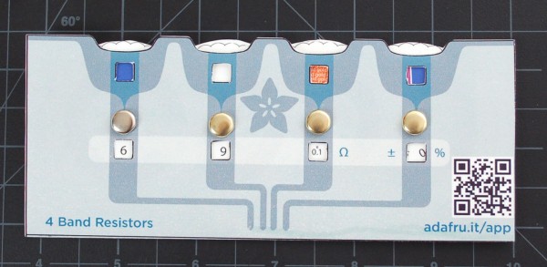 The PDF file is available from Adafruit Industries or a copy is also here. Once you print it out, a little cutting and folding should produce something like the example of the right. The Adafruit design uses brass paper fasteners (remember those?) but any fastener could be used that would allow the wheel inside to rotate freely. It would be best to print on heavy card stock if you have the ability as it will give the calculator some strength.
Something new …
If you happen to have one of those new fangled iDevices you can download Circuit Playground. It has a few more features than the old Radio Shack calculator and looks great on the iPad.
More features are being added but the list at the moment includes:
- Decipher resistor & capacitor codes with ease
- Calculate power, resistance, current, and voltage with the Ohm’s Law & Power Calc modules
- Quickly convert between decimal, hexadecimal, binary or even ASCII characters
- Calculate values for multiple resistors or capacitors in series & parallel configurations
- Store, search, and view PDF datasheets
- Access exclusive sneak peaks, deals & discounts at Adafruit Industries
You can download it from the iTunes Store or, if you have an Android, you can check out ElectroDroid for similar functionality.
As time goes on there are more and more useful utilities available for electronic experimenters on iOS and Android devices. Since more and more equipment today is becoming computerized do iOS and Android devices represent the future of test equipment?
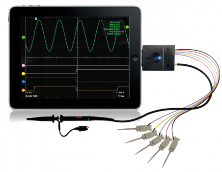 |
| iMSO-104 iPad Oscilloscope |
OAx/K8GU
Loyal readers know that from time to time, I am fortunate to travel to interesting and exotic locales for work—they usually come in pairs, so Greenland and Peru are it for a while. Although the motivation is usually field work, occasionally a conference pops up. The International Symposium on Equatorial Aeronomy occurs every three to four years and can be counted on for an exotic locale. Sarah had such a good time when we attended the 12th ISEA in Crete in 2008 that she insisted on attending the 13th in Peru with me this year. Of course, Evan complicated that a bit, and so we evaluated the pros and cons of leaving him with grandparents or bringing grandparents along, eventually finding a willing pair of grandparents to come along. If you’re interested in a general travelogue (and following posts) and some photographs, you might check out my father’s blogs. This short post is mostly focused on radio aspects of the adventure.
In retrospect, it may not have been such a good idea to bring ham gear to this meeting. Between being the most seasoned traveler in my family and the only one with a functional command of the Spanish language, plus Evan, plus hours of meetings and collaborations each day, there was little time/energy to actually operate. Getting to Peru was uneventful—we took an American Airlines codeshare flight on LAN Airlines via Miama to Lima and got there early in the morning. Unlike their neighbors to the south, Peruvian Customs is by far the most curious I’ve encountered while carrying radio gear—just a minor headache but Sarah was a bit concerned when they took me away for additional questioning. I carry modest gear—a Yaesu FT-840, Astron SS-30 (this should be replaced with something smaller, but it’s what I have), WKUSB, Palm Mini-Paddle, the K8GU portable antenna system, and various cables to connect it all up. After clearing Customs, we boarded a bus to Paracas, where the meeting would be held…

Paracas, which is about four hours’ drive south of Lima, was the site of a major earthquake several years prior and is still in recovery. The hotel that hosted the conference and a few nearby hotels had all been rebuilt from the ground up since the earthquake. The city is on a small bay that is protected from the Pacific. It’s very beautiful—desert sands that go right down to the bay. After a few days at the meeting, I managed to get the antenna set up.

One of the things that surprised me was an excellent JA opening on 20 meters just after sunrise before I went to breakfast and then the meeting. I am pretty sure it was a direct-path opening because the signals did not sound like long path and the long path crosses the southern auroral oval, whereas the direct path does not. (Auroral absorption, by the way, is one reason that the long path can be more effective than the short path.) Any time I called CQ as OA5/K8GU, I was greeted with a roaring pileup. Not bad for an antenna propped up on my veranda. Verticals on the beach rule, and this one wasn’t even really on the beach.
At the request of a friend, I made a special effort to operate on 12-meter CW in the afternoon. The portable antenna would not tune up on 12 meters with the wire radials I had laid out. In a moment of desperation, I assembled some extra pieces of my portable antenna to produce a tuned radial that I clip-leaded to the ground lug as depicted in the photo above. It worked right away and I was quite popular there as well.
A comment about computers—my standard work-issued computer is a MacBook Pro, which although perfect for my work, is essentially useless for amateur radio. I know this will generate a torrent of discussion, but if you are accustomed to real contest/DXpedition logging software available for DOS and Windows, you know that the stuff for the Mac doesn’t cut the mustard. I have logged DX operations on paper (CE/K8GU), or in the case of the OX/K8GU operation, brought along a second computer. However, in a long-delayed flash of insight, I bought and installed VMware Fusion on the Mac in February. It runs Windows XP and TR4W with the WKUSB just brilliantly and with no special configuration. Aside from having to press Fn+F1 to CQ, this was an epic win. KB9UWU tells me that there’s an option in VMware to eliminate this nuisance as well.

After the meeting in Paracas, we returned to Lima, where we celebrated the 50th anniversary of the Jicamarca Radio Observatory. The cornerstone of the Jicamarca facility is a 49.92-MHz radar that feeds an 18,720-element phased array, pictured above. Jicamarca is one of the most powerful radio transmitters in the world, capable of 4.5 MW output, and is used for a variety of atmospheric, ionospheric, and space science experiments. Like Arecibo, it was originally designed to perform incoherent scatter measurements of the ionospheric electron density profile.

Lots of fire in that wire! Have you ever seen a coaxial cable that’s rated for over a megawatt at 50 MHz? This is the feedpoint of the phased array. There are a few tuned stubs in there, too.

Here’s one of the four 1.5-MW transmitter cavities. A maximum of three are used together. When configured for three transmitters, the driver stage puts out 7 kW! Needless to say, everything is custom made on site. The transmitting tetrodes (8973s, if I recall correctly) are refurbished by the manufacturer as needed.
After Jicamarca, we went to Cusco, which is south and east of Paracas, and much more lush than the deserts around Lima and Paracas.

We spent a lot of time being tourists in Cusco and vicinity and I had some difficulty with my computer so I only made a handful of OA7/K8GU QSOs from Cusco on 17 meters. It is quite remarkable how much better the bands were from the coast. As someone who has operated from W3, W8, W9 and W0, I can attest to that difference as well. I missed my morning JA run…
A final thought—we drove through a lot of towns and communities in OA4, OA5, and OA7, on this trip. Nearly every town, no matter how small, had at least one building with an HF fan dipole on the roof. HF is alive and well in a mountainous country like Peru!
QSL information: If you worked OA5/K8GU or OA7/K8GU, the best way to get a confirmation is through ARRL’s Logbook of the World. I have been responding to direct cards (to my FCC address) with a one-day turn-around lately.
Now I understand – Measuring capacitance with a micro-controller
The excellent article by Rajendra Bhatt explains not only how capacitance can be measured but also how a micro-controller can be interfaced to an analog circuit to create a useful piece of test equipment.
 |
| Capacitance meter by Rajendra Bhatt |
I found the explanation of the RC time constant method of measurement as interesting as the micro-processor project itself and congratulate Raj on demonstrating a practical and workable real-life example of what can normally be a dry textbook subject.
A Portable Vertical Antenna
With the loss of my preferred frequent flyer status, airlines tightening their checked luggage allowances, and the addition of another traveler to the family, I’ve been contemplating a new portable antenna that is easier to pack than my usual DK9SQ mast and dipoles. I don’t do high-priced reduced-size antennas if at all possible since portable installations usually have other efficiency-reducing problems. Multi-element antennas take up additional space and have feeding and installation complications that are unnecessary for the casual DX operator. So, that leaves us to choose between a vertical and a dipole.
A few words about efficiency: Dipoles have a distinct efficiency advantage over verticals in almost every practical installation for 40 meters and up, except when the vertical is physically placed in or over salt water. Radiation efficiency tends to be dominated by near-field conditions, pattern is dominated by stuff that’s farther away. This is why vertical dipoles work so well for long-haul DX when placed within a few wavelengths of salt water. They don’t need the near-field efficiency enhancement as much as base-fed verticals, but they still leverage salt water for developing their far-field radiation pattern, especially at low angles required for long-haul communication.
I’m a casual DX operator, not a DXpeditioner, so I never operate on 160 or 80 meters. That is, considering the discussion above, why I have been using dipoles with the DK9SQ. But, verticals have a distinct advantage over dipoles in the sense that they are self-supporting. I decided to build a vertical because: 1) my next DX trip would include time near a beach and 2) I wanted to be able to bring my own support as I had with the DK9SQ.
My remaining requirements were now simple:
- A vertical antenna that requires no additional supports. Guying is OK.
- The antenna must be full-size (quarter wavelength) on 40 meters and above.
- Experience has shown that multi-band operation is desirable, but instant band switching is not necessary.
- The longest piece must fit inside my suitcase (20 in / 50.8 cm maximum length).
- Field assembly and repair with only a Leatherman tool.
- Minimum cost, minimum weight, minimum volume, minimum installation time.
And this is what I came up with:

There are 21 aluminum sections, most with a “swaged” (actually, a poor-man’s swage to be described in a moment) end and a slit end. They are shown here bundled perfectly inside a section of cardboard shipping tube. An 18 x 2.5 x 0.125-inch aluminum plate serves as the base. I used DX Engineering resin support blocks to insulate vertical from the base. A point could be fashioned on the bottom of the base and a foot plate attached to push into soft soil, but that has not been done.


Most sections fit together using overlapping joiner pieces that I previously referred to as “poor-man’s swaging.” I’m not sure that it’s actually a savings over paying a local shop to swage the ends for you when time is considered in addition to material, but I cut telescoping pieces six inches long and fastened them three inches deep in one end of a 17-inch section of tubing with two offset and orthogonally-placed aluminum pop rivets for a total length of 20 inches. This geometry not only fits in my suitcase, but results in a very small amount of wasted material as well.

The other end of each piece is slit about 2 inches and they mate with an all-stainless steel hose clamp. The first 10 feet of the antenna are 0.75-inch 6063-T832 tubing followed by telescoping sizes down to 0.375-inch at the very top. The transition pieces are a full 20 inches long and are slit on both ends. The full-size antenna will stand in a light breeze, but guying is a good idea. Guy rings are fashioned out of flat washers drilled in three places.
Tune-up is easy…the more radials you use, the less critical their length. After about 8 or 10, you’re in the clear here. I never attached enough to prevent them from affecting the tuning. If you only plan to have a couple of radials, go ahead and cut them to 1/4 wavelength (even though ground proximity will detune them). Then, set the length of the antenna using the required number of 17-inch sections (the 234/f formula is surprisingly close) with the last section being a variable length for fine tuning.
I’ve intentionally left out most of the details of the antenna itself because I don’t expect anyone duplicate it exactly. But, here are a few notes for anyone considering building one themselves:
- There are lots of parts vendors out there. McMaster-Carr and DX Engineering will get you there in one order from each. There is a surprising amount of overlap in their inventories. Get the hose clamps from McMaster…even if you get stainless-stainless (stainless band, stainless screw), they are about 1/3 of the DXE price. On the other hand, the resin support blocks are cheaper from DXE.
- I carry a compact antenna analyzer (Autek Research VA-1) with me. Field tune-up is a snap and it runs on a single transistor battery. It’s about 1/4 the size and weight of an MFJ-259 and good enough for amateur work. Oh, and I bought mine used for a fraction of the MFJ.
- A tubing cutter is fine if you only have a half-dozen or so cuts. But, if you have a chop saw or need an excuse to buy a chop saw, it will make cutting the tubing far easier. My hands were raw for a few days after cutting the tubing by hand. I’m sure the antenna performs better on account of it, though.
- Find a friend with a metal-cutting bandsaw to slit the ends of your tubes. I went through a half pack (McMaster mega-size pack) of cut-off wheels for my rotary tool doing my slits.
- McMaster only sells the aluminum plate in 36-inch pieces. If you don’t have the aforementioned chop saw, an angle grinder with a cut-off disk does a surprisingly good job.
- I pack a combination-screwdriver that has hex drivers that fit the hose clamps and #6 nuts. Even though the antenna can be erected with only a Leatherman tool doesn’t mean it has to be.
- The small parts box shown in the top picture holds all of the parts for the antenna—it was 2 USD at Home Depot.
- The final and most critical component is a clip-lead that can be used to attach various nearby metal structures to your ground plane. I have used it to make a temporary radial out of excess tubing sections on 12 meters as well.
That’s it. The antenna goes up in a few minutes, especially if not used at full length. I used it successfully last week as OA5/K8GU, which will be detailed in a future post.
W1GHZ 903-MHz TX Gain Compression

I managed to sneak into the lab again at lunch today for a few minutes and hooked up the now-packaged W1GHZ 903-MHz transverter to do a transmit gain compression test. This test is a quick and dirty way to find the linear operating region of the transverter in addition to the expected conversion gain on transmit. These two parameters determine the IF transmit level and what kind of power amplifier or driver stage will follow. It’s an easy test to run if you have the equipment. I locked the transverter in transmit by applying 8 volts to the TX MMICs and used a Rodhe and Schwarz SMR40 signal generator as the IF transmitter at 147.100 MHz. On the transverter TX output, I simply connected the HP 8565E spectrum analyzer that I’ve used in the past. Spectrum analyzers are not great power meters, but they give you a good enough idea of what’s going on. The 1-dB gain compression point (that is, the point where the actual device gain sags 1 dB from the linear gain) is at an input of -3 dBm or an output of just under 10 dBm. This compares favorably with the datasheet for the mixer and discussion with N3UM.


