Posts Tagged ‘engineering’
 Pin 1 and a Pound of Ferrite

The commonly-held wisdom goes that an “ounce of prevention is worth a pound of cure.” As things typically go around the K8GU station, 50% of problems are solved by prevention and 50% by cure. Today, it was a cure. Readers of the blog are no doubt aware that I have a recently-discovered problem with QRM between my radios when they were on the 20- and 40-meter bands. (I didn’t notice this problem until I got both of the TS-930′s up and going again; so, it’s probably the result of the “new” station location and arrangement.)
I pulled the 20- and 40-meter W3NQN filters out of the circuit and measured them. They benefited from a little tweaking, but nothing that would have caused the problem. I put them back in and was rewarded with much lower VSWR in across both bands.
It didn’t matter which of the radios was on 20 and which was on 40, the interference, a popping hash that followed the leading edge of my keying, was there. The next step was to put a dummy load on the output of one radio, then both radios. Even when transmitting into the dummy load, the interference remained. This suggested to me that the problem was very close by. All of my gear is bonded together with heavy straps. So, I wasn’t too worried that it would be difficult to find. I noticed that the 40-meter LED flickered on my KK1L band decoder box following my keying. It became the prime suspect.
I found some split beads that AD8P and I bought from AA1K in the Dayton flea market a few years ago. I’m not sure what mix they are, probably 43 or possibly 77. Winding a few turns of the band data lines from each radio through the beads knocked down the interference a good bit. I slapped some more on the audio lines going to the Heil HCS that I use for SO2R audio and the interference disappeared. But, I was using the dummy load on one of the radios. As soon as I went back to the external antennas, the inteference came back.
Next, I dug out a couple of the 2.4-inch diamater mix-31 toroids that I purchased in the first K9YC “group buy” of these parts back in 2005 or 2006. I wrapped the DC power supply line to the KK1L box and the AC supply to the HCS. And, the problems pretty much disappeared. At least one of these is due to what K9YC calles “the pin 1 problem.” Basically, if the shield is brought through the metal enclosure to the circuit board, it conducts (noise) current that’s riding on it into the enclosure. So, I need to dissect the HCS and KK1L boxes to see if I can find a deeper fix than just slapping ferrite on the outside.
But, there’s hope for SO2R in this week’s NSL!
VHF/UHF firepower

As if I don’t have enough projects already, I recently obtained these two surplus FAA AM-6155 amplifiers on, as usual, very attractive terms. I don’t have the equipment to properly test them at this point. But, that is coming. The FAA specified these to do 50 watts continuous duty AM. With modification, they will do about 300-400 clean watts with 10 watts of drive on 144, 222, and 432 MHz. Once I get the first two working (on 222 and 432), I plan to find two more of them and use them on 50 and 144 MHz. For 50 MHz, I plan to remove the VHF/UHF cavity and components and install an RF deck using the same Amperex DX393 or Eimac 8930 tube. Comments and ideas welcome. They’re a lot cheaper than bricks! One of my units appears to be at least partially converted already, but I’ve only had it open for a few minutes with my brother Seth, who got all of the mechanical aptitude in the family.
Note: Thanks to WY3X for catching my error on the tube type. He also notes that 300 watts would be a conservative maximum on 432. I plan to run the amps with very low drive after tuning so I can compete in the ARRL’s low power category at 100 watts on 222 and 432.
K9AY loops
When I lived on my parents’ farm in Ohio, I used to install Beverages. That was back when copper was cheap and I bought 500-ft rolls of #14 THHN for $10 each. N8ET gave me some ferrite toroids (of unknown mix, probably 77) and I added some parts from RadioShack to build some killer listening antennas. The best setup was three unterminated (bi-directional) ones that covered the compass. When I lived in Minneapolis, I went to W0AIH to operate the low bands. And, when I lived in Urbana, IL, I didn’t operate 160 and didn’t need the low-noise receiving antennas—or I went to NO9Z. Now, I live in the suburban wasteland between Washington and Baltimore. It was time to do something about the receiving situation.
Armed with my (autographed, no less) copy of ON4UN’s Low-Band DXing, I began thinking of what options I had. A small RX 4-square developed by K9UWA, W8JI, and others was appealing. But, it’s too large to fit comfortably on my lot. I considered a pair of short verticals with a phasing box (a project that has been in my queue longer than any—since 2003). But, I ended up settling on the K9AY “loops” because they are small and portable, having an integral ground radial and a single ground rod.
When I lived in Urbana, I had considered doing a set of K9AYs. So, I had purchased the parts to build a nice balanced preamp based on a QEX article by IK4AUY (this design is actually based on an even older Ulrich Rohde design). Note that the version of this preamp presented in ON4UN’s Low Band DXing, 4th edition, is wrong—if you see IK4AUY’s web site you shouldn’t miss it. Several months ago, I had assembled one on a perfboard (and tested it—so I thought). When I tried the preamp again over the weekend, it didn’t amplify the signals on the antenna side. The 2N5109 transistors are heat-sinked and so should get warm to the touch during operation. They did not. This suggested that they weren’t even being biased properly. So, armed with a DMM and the schematic, I started following the Vcc line. Megaoops. I failed to connect the collectors to Vcc. That fixed the problem and the preamp worked like a charm.

I built the classic K9AY crossed loops at 90 degrees for four-direction switching. Here’s my switchbox (built using 48-volt relays scavenged from the AT&T Long Lines system in the post “Resume of a Master Dumpster Diver“).

This box may have layout problems. If you’re an expert on K9AY loops, please weigh-in. The terminal strip at right is for the control wiring. I had originally planned to run Siamese RG-6 (scavenged from a DBS installation initiated by some lying, theiving, lazy, pot-head, good-for-nothing duplex neighbors we had in Urbana—they also discontinued our shared “free” Cable) so the loops could be independently switched and shared between two transceivers. But, when I suggested this idea to K9AY, he told me that the loops couple strongly with each other unless the unused loop was left floating. (If this idea actually did work, you could use two transformers on each loop, one in place of the termination, like a reversible Beverage…hmmm…for maximum flexibility.) Instead, I built the regular control box, with a scrap of CAT5 cable as the control cable.

And, zoomed out…

The loops are 80% of full size due to the amount of space (and wire) I had available. I terminated them with a 330-ohm resistor, although I’m having a hard time getting a null. Unfortunately, this is one of the best sites in my yard, yet it has a rusty metal fence (i.e., lots of little diodes on a big antenna) on two sides, a 30-ft mast and my 80-meter vertical on the other two sides. So, it’s not entirely unexpected that I’m not getting a null. I suspect that the neighbor would let me install it in his back yard, but I don’t want his landscape guys to hit the cables. This may become an option.
After conferring with N3OX, I tried putting a 500-ohm potentiometer on the termination point. But, that didn’t seem to help. I probably should bring a receiver out to the antenna when I do this…shouldn’t have sold that FT-817. I checked the potentiometer with my antenna analyzer and it looked pretty reactive. So, that could have been part of the problem. For now, I have the 330-ohm resistor in there and get 10ish dB F/B when I’m lucky…
TS-930S PA/PS Postscript
Long-time followers of the blog know that one of my TS-930S transceivers has been a money and time sink for about the past five years, fully 60% of the time I’ve owned it. So, if you haven’t been following the story over the past couple of months, I pretty much replaced (almost—get to this in a second) all of the electrolytic capacitors in the power supply and power amplifier, plus replaced the driver and final amplifier transistors. As I increased the drive past the point where I got 50 watts output, I started to get a lot of AC hum on the signal.
At first, I thought the hum might be associated with a low-frequency instability in the power amplifier. I read all the Helge Granberg articles I could find on the topic and tried all of the prescriptions he suggested. Last night, I even went so far as to tweak the feedback resistances in the PA stage to increase low-frequency stability. Still there. Finally, I measured the frequency of the AC hum—exactly 120 Hz—full-wave bridge rectifier leakage. Tonight, I pulled the power supply board out of the radio, which is a herculean task, by the way. There were still three small, insignificant-looking electrolytic capacitors that I hadn’t changed. I found two of them in my junk box and crossed my fingers on the third one (a 25 uF, 100-volt unit), leaving it in place. While I had it out, I also found and shunted a pair of dying PCB traces with pieces of wire.
After putting the board back into the radio, I disconnected the PA 28-volt line and powered it up. I checked the 28B voltage…right on 28.5 volts. So, I reconnected everything and it fired right up at 100 watts without the hum. Perseverance seems to have paid off. For now. I keep telling myself that the next time it breaks, I’m going to get a K3/100. But, I just can’t bear to buy a radio that’s worth more than my car.
Super-sizing the “cheap Yagi” (Part 2)
The two most expensive parts of a VHF/UHF Yagi are the boom hardware and the feedpoint. So, I set about eliminating these costs, keeping in mind that I may only have the antenna installed for a year or two at this QTH.
The feedpoint mechanical construction has been addressed in a previous note. However, I should back up and discuss changes from the K1FO Yagi. In its original configuration, the K1FO antenna is fed with a T-match. This is mechanically complex, although some might argue that it’s sturdier than my solution. I elected to feed the antenna with the WA5VJB hairpin design (38-inch element with harpin 1/4-wave stub spaced 1 inch for 19 inches—this is just a convenient and inexpensive ruse for direct feed without splitting the driven element) for the moment. Yes, I am aware that the K1FO antenna has a natural input impedance considerably lower than 50 ohms, but this is just the first (essentially mechanical) prototype. I’ll do some modeling eventually and determine if I can or should optimize it further.
There are four choices for a boom: PVC pipe, fiberglass, aluminum, or wood. PVC is heavy and too flexible for anything longer than two or three feet. (I see people asking questions in forums all the time about building antennas out of PVC. Why bother when wood and aluminum are so readily-available?) Fiberglass is light and strong, but unless you have access to a lot of it, it’s the most expensive of these options and the most difficult to work. That leaves aluminum and wood. Aluminum is hard to beat for strength-to-weight ratio and ease of working. But, wood will give it a run for its money on cost for a reasonable strength up to a point. Since I had a bunch of wood readily available, I elected to build the boom from wood. This is probably pushing the practical upper limit for a wood-boom antenna.
For the boom, I used three pieces of 1 x 2 select pine that was weatherproofed with a clear lacquer:
![]()
The 0″ reference point for the element position measurements is at the left end. Don’t forget to leave a couple of inches at the end.
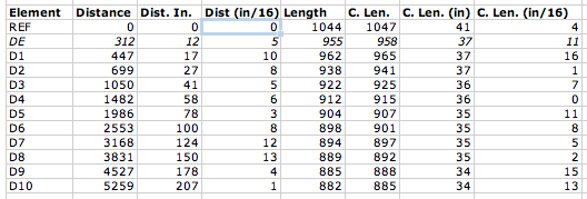
The original WA5VJB designs were optimized for 1/8-inch diameter elements, which is fortunately quite inexpensive (part #8974K14, $2.11/each, working out to a $12.66 antenna, plus about $5 for shipping…you can buy a lot of Al rod and still ship it for $5.) from McMaster. The K1FO designs are provided for 3/16- and 1/4-inch elements, costing $4.13 or $6.03 for six-foot pieces respectively. That was a little rich for my budget, but then I looked at the Metric-dimensioned 6061 aluminum rods. 5 mm is a little more than 3/16 inches and these rods are only $1.64/each ($19.68 for 12 six-foot lengths; examining the element length table below should give you an idea how much savings there is if you get some buddies together to build a few of these…forget buddies, build an EME array)! So, I built the antenna out of 5-mm diameter rods using the 3/16-inch dimensions.
The table contains initial element lengths and offsets in inches. Do not build this antenna! (Do as I say, not as I do.) It appears to be a good performer, but it has not yet been optimized as discussed above. The columns “Dist (in)” and “Dist (in/16)” refer to the integer and fractional portions of the distance, respectively. Likewise, “C. Len. (in)” and “C. Len (in/16)” refer to the element lengths.

Using a cheap Dawia SWR meter at the end of the feed cable, I can tell that the SWR is less than 1.7 across the low portion of the band. Actually, it’s relatively flat around 1.5-1.7 all the way up to 144.5 MHz where I quit measuring. The pattern is apparently good. My “local” beacons that I can pretty much always count on are WA1ZMS (to the southwest) and W3APL (to the northeast). WA1ZMS runs a lot of gas to an excellent antenna system from an even more excellent QTH. I can fade either of them into the nulls when listening to the other. When I turn the antenna, they fade pretty rapidly into the noise, as well. Good F/B, F/S, narrow forward lobe, etc.
So, the upshot is: I built the unmodified K1FO-12 design for 144 MHz on a wood boom for $30 and about 5 hours of tinkering with basic hand tools. I can turn it and my 3-element 50-MHz Yagi with a 60-year-old CDE TR-2 TV rotor. My TS-700S happily blasted 10 watts into it even at SWR of 1.7. I’ll need to verify the cable loss and determine if my newly-acquired Mirage B3016 will tolerate it.
I will post models and photos eventually (once I find the files again…oops) for the 11-element disaster and the 12-element one I built. Yagis are tricky to optimize well. So, I’m somewhat disinclined to mess with the K1FO design and more likely to switch from the WA5VJB driven element to the T-match if I decide that the SWR matters that much.
Super-sizing the “cheap Yagi” (Part 1)
One of the frustrations of doing VHF on the cheap is getting enough gain to make your low-power signal loud (or simply being heard) at the other end. I had a couple of options with my 6-element WA5VJB “cheap Yagi” on 2 meters:
- Increase the height of the antenna. This is impractical at the present QTH without installing a tower. Actually, the tower would have been possible but I wasn’t ready shoot first and ask questions later with it. Nor was I ready to have my folks spring some Rohn 25G out of storage in their garage for the trip here when I had the opportunity (a truck bringing some furniture from them).
- Run lower-loss cable. I have regular old RG-8 (PE dielectric) running up to the antenna. It’s only about a 50-ft run. So, I’d be hard-pressed to do a lot better. I did figure out how to recycle improperly-installed N-connectors for LMR-600 from a dumpster-diving excursion. Although I have twenty-some connectors, I haven’t yet secured any scraps of LMR-600 to use. This is a future consideration. At $1.50/ft, LMR-600 would still cost $75. No deal.
- Stack multiple 6-element antennas. This is actually a good idea that I’m keeping in the back of my head for the future. It would be nice to do something like this. Maybe some day.
- Launch a rocket to do a chemical release whenever/wherever I needed a sporadic-E layer. Unfortunately, you can’t launch rockets over land. (Update: I was reminded later that this is not 100% correct.) Furthermore, at a megabuck per shot, it’s not cost-effective.
- Dispense with the 6-element design and go for something bigger.
I elected option #5.
The first step was to consider suitable designs. I tried scaling the 11-element 432-MHz cheap Yagi to 144-MHz. Fail. A NEC model showed that the pattern stunk and the input impedance was pretty far from 50 ohms. Knowing that W5UN had built an array of wood-boom antennas for his EME setup, I looked into readily-designed options.
The ARRL Handbook (1993 edition for reference) and ARRL Antenna book (18th edition) have the K1FO optimized Yagi designs in them. This antenna has been around for a number of years (clearly) and is available commercially from Directive Systems. It seemed like a relatively good choice. So, I moved forward with it…
Feeding the WA5VJB cheap Yagis
The WA5VJB cheap Yagis are a great way to get on VHF/UHF without spending a fortune on commercial antennas. While it is practical on the UHF/microwave bands to use a copper driven element, it is less practical on the 144 and 222 MHz bands. I know that McMaster carries copper and brass rods, too. But, I also like to have a coax connector at the feedpoint. Since I am in the process of building what amounts to a “super cheap Yagi” (note that’s not a “super-cheap Yagi,” the hyphen matters; will report on this in the future), I figured I would share my feedpoint for aluminum driven elements.
While wandering through the electrical aisle of the local big box hardware retailer about six months ago, I discovered the Thomas and Betts ADR6-B2 (try the ADR6 for a drawing of a similar part) grounding lug. This looked like a good candidate for the cheap Yagi feedpoint, especially costing only $1 for a pair. In order to fit an SO-239 flange-mount connector to the ADR6-B2, I cut off the portion of the lug with the bolt hole and drilled my own hole (#43) and tapped it 4-40. I did the same to the other piece. I did not cut off the lug on the second one, but I should. Then, I soldered a short piece of wire to the center conductor of the SO-239 jack and added a lug to it. Here are the parts so far:

Then, I assembled the whole mess on the J-shaped driven element (dummy used for photos) using two 3/8″ 4-40 screws and a lock washer. Note that the ADR6 lugs are installed on opposite sides of the element.

And, after installing on the wooden boom, it looks like this:

It’s not quite square and some mechanical strengthening is in order before it goes up in the air. But, this is a considerable improvement over what I’m using now. Ty-wraping the coax to the boom will provide considerable relief to the connector and it’s attachment. More details will be forthcoming on the antenna, if it works. Stay tuned!


