Posts Tagged ‘engineering’
 Just Get On The Air! (A Makeshift Temporary Dipole Shortwave Antenna)
It might not take as much antenna as you may think would be necessary to make two-way contacts on shortwave radio (as an amateur radio operator putting an HF transceiver on the air). However, often, makeshift antennae are effective enough to be viable–just look at all the contacts many amateur radio operators make with their low-power (QRP) rigs (transceivers) using short, helically-wound, mobile antenna sticks. If they can work magic with such inefficient antenna setups, surely your effort at an antenna would pay off to some degree. Right?
[embedyt] https://www.youtube.com/watch?v=-k5Su–ez2Y[/embedyt]
Of course, I want to make a proper dipole out of this example antenna. But, while I wait for the rest of the parts I need to complete this antenna project (pulleys and a ladder, and maybe a potato launcher), I’ve put this makeshift antenna on the air, with it just high enough so that I can enjoy some time on the shortwave bands.
With this antenna, I’ve made successful two-way voice and Morse code contacts (QSOs) with stations in Europe and across North America. I am able to tune it on the 60-, 40-, 30-, 20-, 15-, 17-, 12-, and 10-Meter bands. Reverse beacon detection picks up my Morse-code CW signals, especially on 40 meters (the band on which it is tuned physically).
The bottom line: just get something up in the air and start communicating. Improve things over time. You’ll have much fun that way.
73 de NW7US dit dit
FCC Opens 630/2200 Meters Amateur Band; Pre-Registration Required!

Yes, the headlines read, “FCC OPENS 630/2200 METERS TO AMATEUR USE AS OF OCTOBER 16, 2017; PRE-REGISTRATION REQUIRED.”
The FCC has authorized amateur radio use of the 630 and 2200-meter bands, effective October 16, 2017, providing registration procedures have been followed and no objections are received within 30 days.
The PLC (Power Line Communications) database is live and hams may begin registering immediately. They may begin operating on 472 kHz (630 meters) and 137 kHz (2200 meters) as early as October 16 if they register today and receive no objection in the next 30 days. Hams may not operate on the bands without going through this process.
Please fill out the UPC Form, today, to register your station, even if you don’t have any plans on transmitting on these new bands.
It is imperative that all amateurs register, even if they don’t plan to use these bands in the near future, as the FCC rules prohibit UTC (the Utilities Technology Council) from deploying PLC in these bands closer than one (1) kilometer from registered stations. Registration now will protect your ability to use our new MF/LF bands in the future.
Making the Palm Mini Paddle Stay Put
In my on-going quest to produce a lightweight yet good-performing kit of portable equipment to carry along on my exotic work travels, I set my sights once again upon the Morse keying paddles. When I was a student, I carried what I had: a black-base Bencher BY-1. This caught the attention of nearly every airport security screener and was obviously quite heavy, but it stayed put on the table (for the most part) when I aggressively worked a pileup. A few years back, my wonderful, loving, and patient wife, solicited suggestions for Christmas gifts and I suggested a Palm Radio Mini Paddle. (She’s grateful when I provide a link to a web site with a shopping cart in these situations.)
The Palm is really a joy to use and is extraordinarily lightweight, which is perfect for travel. However, I’ve always struggled with how to keep it steady on a table. I have the magnetic base, but that presupposes a ferromagnetic surface to which it will mount. Since both the Elecraft K3 and K2 have aluminum panels, I can’t count on the radio. I tried a variety of additional things, up to and including, trying to design a 3D-printed carrier that is akin to the Begali Traveler. So, I shelved the project, only using the Palm key for casual portable operating when mass trumped long-term operating comfort and efficiency. Good fortune happened upon me and I built this.
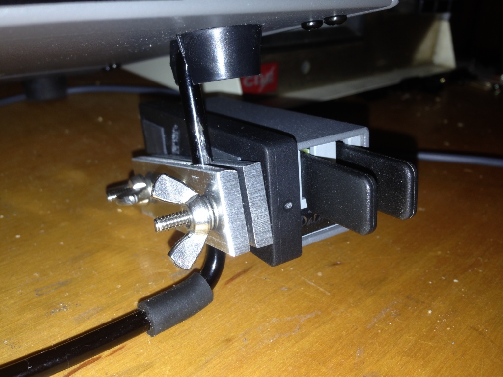
When I decided to add an amplifier (more on this in the future) to my portable setup, again pressure set in on the mass of everything. So, I revisited the Palm Mini project. I had purchased a number of mounting clips for the key (hedging my bets against the ephemeral nature of ham radio businesses); so, I set out to attach one to the K2. I’d seen the photo of the base attached to the right-hand side panel of the K2 by the power switch. But, I really didn’t want to drill holes in the panel, plus that puts the paddles too high when the tilt bail is raised (which is necessary to see the display).
So, I fabricated two strips of 3/16-inch aluminum plate (leftover from the hexagonal beam I built a few years ago) with a hole bored down between them to clamp on the tilt bail of the K2 or the K3. There’s nothing particularly critical about the construction of it, although I used a Bridgeport mill to do all the cutting; you might be able to do it in a drill press. I think I ended up with a #14 drill for the clamp hole. I used 6-32 hardware because I had it on-hand and I like the bigger stuff. I had to enlarge the adjustment slot in the Palm base to handle the bigger diameter.
50-MHz transverter update (Psst! Newark has cheap 22-MHz crystals)
A few years ago, I built a 50-MHz transverter to operate 6m with my Kenwood TS-930Ses. I subsequently replaced the two 930s with an Elecraft K3/100 and Elecraft K2/100. The K3 has 6m and I sold off my TS-700S (and my 6m Mirage brick amplifier) to help finance the internal 2m board for the K3. The problem with this arrangement is that I can’t be on 6m and 2m at the same time. I recently assembled and added the SSB board and transverter interface to my K2 (no time to blog about this but they were straightforward additions like everything from Elecraft), now making it an attractive IF for the 6m transverter (and the Microwave Modules 432 transverter I have on the shelf and the 222-MHz transverter I plan to build sometime).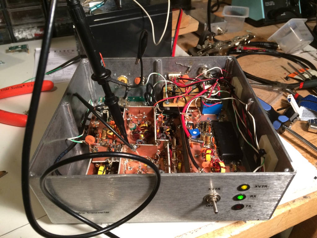
Enter the problem: Because I was thrifty about building the transverter at first, I had used an inexpensive and widely-available 24-MHz crystal for a 26-MHz IF. The TS-930S happily worked here (by the way, pro-tip: A lot of guys say that they liked to have the wideband transmit mods on their HF rigs so they could have a wideband signal source for testing/transverters/etc. The TS-930S will give you a low-level TX out anywhere through the transverter port, even if you don’t have the mod. Well, at least my PIEXX-equipped 930 did). However, the K2 only allows a select set of transverter IF bands to be used natively. Good fortune shone upon my endeavors when I did a quick Google search for 22-MHz crystals and one actually popped up at Newark/Element14 (part number is 86R1720, get ‘em while they’re hot)! Even better news was that it was on closeout for 12 cents apiece! I splurged and bought five, along with some other parts for another project or two I’ll post about eventually.
I carefully peeled back a layer of dead-bug components, extracted the 24-MHz crystal, and replaced it with the new 22-MHz variety, sacrificing only one 4.7-k resistor, an easily-replaced stock item at K8GU. The LO came up about 5.4 kHz low and I couldn’t peak it any higher. So, I’ll either have to futz around with the loading of the crystal or (more likely) load an offset in the K2’s transverter band entry for 6m.
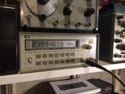
The local W3APL beacon popped up at 28.0694 MHz, which is consistent with the offset I observed above. Now, I just have to get the other interfacing juju worked out to get the K2 to properly command the transverter to transmit and feed it the proper drive level.
Converting the HP ESP120 Power Supply
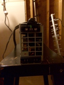
Quick notes on converting the HP ES120 2950-watt blade server power supply to run “48-volt” amateur radio amplifiers. The power supply I have has a slightly different in configuration from the one described by W8ZN on the K8GP site.
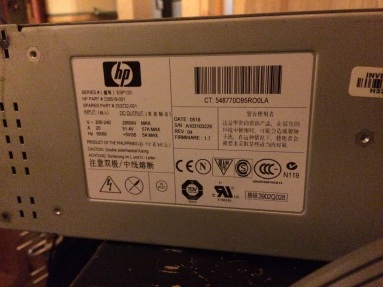
I picked up the power supply on good terms at Dayton some years ago and finally managed to get around to hooking it up after I put two 240-volt, 20-amp circuits in my shack this spring/summer. I used a molded air conditioner extension cord with the female end cut off to attach it to the wall. Hot-ground-hot is the wiring on the AC input side. On the output, there is a jumper block and two pairs of blade connectors, with one pair being positive and the other negative, strapped together. In the middle of the output there is a jumper block.
Here is where the steps differ from the W8ZN steps: instead of shorting two pairs of pins together, this power supply requires three in a line to be shorted together. It’s visible in the photo below, I think. The center row.
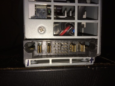
I’m getting 51.4 volts unloaded. Load will be described in the future as it comes to be…
Amateur radio as a gateway to a career in engineering?
See http://www.kb6nu.com/is-amateur-radio-still-a-gateway-to-electrical-engineering/ .
At one time, amateur radio was a good gateway into an engineering career, but I have real doubts this is true today. In my younger days, when I started as a professional radio engineer nearly everyone who was any good was a radio amateur. When I left 7 years ago, I was the only person doing any amateur radio building over my lunch break. The magic is no longer there. In fact people are embarrassed to admit they are radio amateurs. We need to find what connects with the younger generation or the future of our hobby is at great risk.
I think I have mentioned on my blog before that when interviewing potential RF design engineers with good honours degrees I was appalled to find that most knew nothing about radio. I knew more as a schoolboy. This is a sad indictment of our times. It was not that I was good (I was not) but the quality of good engineers was not there any more. There was little intrinsic interest in radio – if it was in the course they might know about it. As youngsters, we were excited about radio! Where is that spark today?
The Pi Day Contrarian
I may be the only person on the Internet who, despite its namesake, finds “Pi Day” on March 14th completely irrational. Here’s why: It’s completely arbitrary. Only we in the U.S. write the date with the month before the day and year like mm/dd/yy. This violates everything sacred about significance in number systems. Normally, digits are ordered from most- to least-significant left to right or least- to most-significance. So, Pi Day including the year actually wouldn’t occur until 3141/59/27 or 31/41/5927, neither of which are real dates anyway. Therefore, Pi Day doesn’t actually exist. I propose a rational alternative definition of Pi Day to be July 22nd (22/7) of every year. Besides, red raspberries are in season in July and not in March so I can enjoy my favorite pie.


