Posts Tagged ‘Digital mode’

JT9 and 100 Hz ghosts

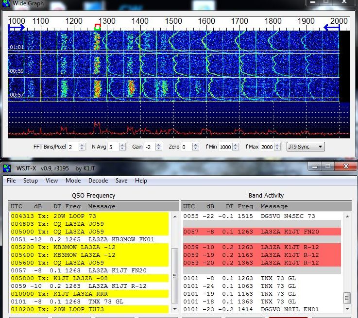
Multiple decodes at 100 Hz spacing of K1JT
on 30 m on 28 April 2013, 0101 UTC

From time to time I receive duplicate ‘ghost’ decodes at 100 Hz intervals on either side of the main signal. Last night I saw the phenomenon on 30 m. You will notice here that I have decoded the message: “TNX 73 GL” four times (press image for better readability):

  • -24 dB, 1063 Hz
  • -19 dB, 1163 Hz
  • -8 dB, 1263 Hz
  • -18 dB, 1363 Hz
The actual contact took place at the frequency of the strongest one, 1263 Hz. The station is only moderately strong at -8 dB and at +/- 100 Hz the first sidebands are 10-11 dB down and at -200 Hz the second one is 16 dB down.
In the post “Ghosts on JT9-1” Julian, G4ILO speculated that it had to do with strong signals. His best example showed a very strong example with signal strength as high as 19 dB and with the +/- 100 Hz ghosts 37-40 dB down, much more than in my example. A commenter proposed that it had to do with the mains frequency and that a North American station should have ghosts at +/-120 Hz instead. 
In his second posting, “Ghostly signals“, Julian did some tests and found that a mains power supply can indeed result in weak 100 Hz sidebands. Then it was commented on the wsjtgroup that in the US people see these ghosts at a spacing of 120 Hz and that tests suggest that they are generated at the transmitter end.
But my example is from a US station, and the ghosts are still at +/- 100 Hz, so that theory does not seem to be right. My example indicates that it has to do with the receiver and not the transmitter. It comes and goes and the relative levels seem to vary a lot. My guess is that it is 50/100 Hz that enters the audio signal between the receiver and the PC. The software was the latest v0.9, r3195.
And by the way, the US station in my example happens to be Joe Taylor, K1JT, the originator of the JT9 mode and the decoding software.


See also “Overmodulated JT65 on HF?

Overmodulated JT65 on HF?

Sometimes it is crowded on JT65 on HF due to too little bandwidth. When only 2 kHz is available and each signal needs 175 Hz that’s understandable. But then others seem to complain that some overmodulate their transmitters so that they occupy more than the 175 Hz, making it even harder to fit an extra signal in the band.

As I have been running a lot of JT65 lately on HF, I also have seen this phenomenon and it pickled my interest to try to understand what was going on. The image below shows such a strong station to the very left, at about -1000 Hz where the red marker is located. After some seconds I turned on the attenuator of my K3, so the signal was attenuated by 10 dB (press image for zoom).
What one can see is that what appears initially (at the bottom of the waterfall) as a splattering signal, becomes quite fine when the attenuator is turned on. Then it spills into neighboring frequencies again as the attenuator is turned off again.
It appears then that it is the JT65 decoder software which is too sensitive to strong signals. Now, I cannot really say that I understand all of the decoder code, but I think that it has to do with the way the power spectrum is estimated. The FORTRAN code for ps.f is listed below. It comes from the BerliOS repository for WSJT which has the same code for this routine as JT65-HF-Comfort:
subroutine ps(dat,nfft,s)

      parameter (NMAX=16384+2)
      parameter (NHMAX=NMAX/2-1)
      real dat(nfft)
      real s(NHMAX)
      real x(NMAX)
      complex c(0:NHMAX)
      equivalence (x,c)

      nh=nfft/2
      do i=1,nfft
         x(i)=dat(i)/128.0       !### Why 128 ??
      enddo

      call xfft(x,nfft)
      fac=1.0/nfft
      do i=1,nh
         s(i)=fac*(real(c(i))**2 + aimag(c(i))**2)
      enddo

      return
      end

What is apparent here is that the raw data, dat, is just put directly into the Fast Fourier Transform routine, xfft, after scaling. There is no windowing function. A window function tapers down the beginning and end of the data set. Window functions in spectral analysis are somewhat involved and I refer to the Wikipedia article for details. But when there is no window function (= rectangular window), the first sidelobe is only 13 dB down from the mainlobe. So that could be why a 10 dB attenuator is enough to remove most of the spillover into adjacent frequencies above. 

This could be remedied by using a smooth window function. There are many to chose from, but let’s take a Hamming window as an example, with its first sidelobe 43 dB down. This means that if the data had been multiplied by this taper, the dynamic range would  have been in the order of 30 dB higher. But as data is lost by the tapering, the downside is that the bin width increases. For this particular window the noise bandwidth goes up by a factor of 1.36 so sensitivity would suffer by 10log(1.36) or about 1.3 dB (ref: Harris, “On the use of Windows for Harmonic Analysis with the Discrete Fourier Transform,” Proc. IEEE, 1978)There could potentially be other negative side effects on decoding also which I cannot foresee from the limited  time I have used in trying to understand the algorithms. 

My first impression from using the new JT9 mode is that the problem is much smaller there than for JT65, so maybe something like what I am discussing here has been done in the decoder software. But as far as I know, the source code has not been releasted into the public domain yet by K1JT, so I cannot verify it now.

But it seems clear to me that what looks like splatter has much less to do with overdriving and overmodulating transmitters than one may think, and more to do with the particular way that the spectral estimate is found in the JT65 decoder software. Combined with the variable propagation which is an intrinsic feature of HF and which may create a highly variable signal strength, this is what seems to create the spillover.

Half a year of APRS temperature monitoring

My APRS-based temperature monitor has now worked flawlessly for half a year. APRS stands for Automatic Packet Reporting System so it can send much more than temperature data, the chief usage is really for GPS position reports.

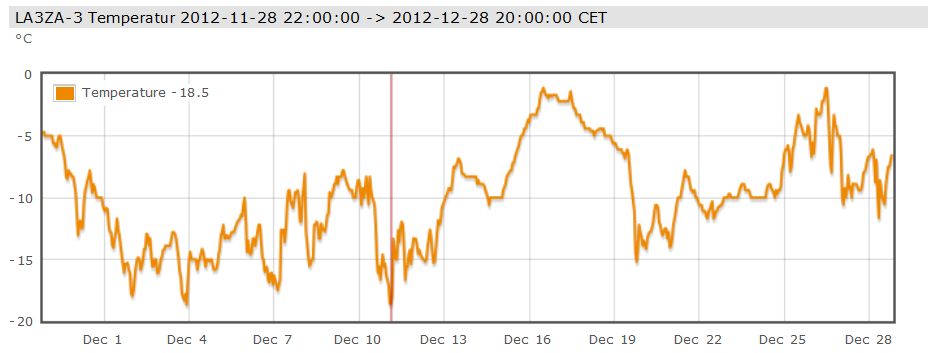
But I just needed a temperature monitor and here are the readings for December. As one can see, there were no days with temperature above freezing. At 800 m elevation in the mountains of Telemark in Norway, this is not unexpected for this time of year and makes for good skiing!

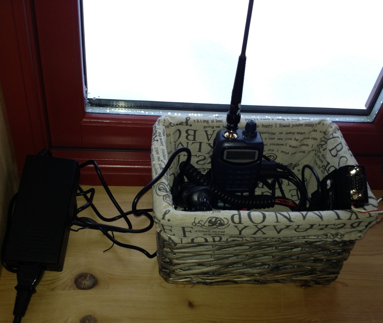
I use a Quanzheng TG-25AT handheld with a quarter-wave whip antenna on 144.800 MHz. Its signals reach the LD3GT digipeater at 1845 m above sea level. Although I don’t have direct line of sight, the low power (1 Watt) setting is adequate as the distance is only 10 km. The APRS-beacon is an OpenTracker USB set up for transmission every 15 minutes. An external DS18S20 temperature sensor which measures the outside temperature is connected to the 1-Wire® bus of the OpenTracker USB.

Thanks to the infrastructure providers: The Tønsberg group of NRRL (LA1T) who operate the LD3GT digipeater, probably the one with the largest coverage in Southern Norway (Gaustadtoppen). Thanks also to the various operators who receive packets from LD3GT and pass them on to the internet, and thanks to aprs.fi for processing and displaying the data on their excellent web site!

My first 24 hours on WSPR

My first beacon on 30 m, a free-running Ultimate QRSS kit (no GPS) has now been running for a full 24 hours using the Weak Signal Propagation Reporter (WSPR) mode. The figure comes from the WSPRnet page.

With an output power of about 150 mW to an 80 m horizontal loop it has not been possible to reach beyond Europe so far. Perhaps this will happen in the future with better conditions and/or with some more output power.

Added 26.9.2012: I made it for the first time across the Atlantic!
Timestamp           Call       MHz         SNR Drift  Grid      Pwr Reporter   RGrid      km      az
2012-09-26 00:50, LA3ZA, 10.140262, -26,   -2,   JO59fu, 0.2, WB2EEE, FN21xh, 5852, 290


Subscribe FREE to AmateurRadio.com's
Amateur Radio Newsletter

 
We never share your e-mail address.


Do you like to write?
Interesting project to share?
Helpful tips and ideas for other hams?

Submit an article and we will review it for publication on AmateurRadio.com!

Have a ham radio product or service?
Consider advertising on our site.

Are you a reporter covering ham radio?
Find ham radio experts for your story.

How to Set Up a Ham Radio Blog
Get started in less than 15 minutes!


  • Matt W1MST, Managing Editor


Sign up for our free
Amateur Radio Newsletter

Enter your e-mail address: