Posts Tagged ‘Data Modes’
 Interested in Amateur Radio Digital Mode FT8 Operations?
A VISUAL + AUDIO AIR CHECK OF DIGITAL MODE FT8 QSOs, ON THE 30-METER BAND
Here is a video capture of the reception and transmission of many digital FT8-mode amateur radio high-frequency (HF; Shortwave) communication signals. This video is a front-seat view of the software operation performed at the radio room of amateur radio operator, NW7US, Tomas Hood.
The software packages demonstrated are installed and operational on a modern personal computer. The computer is connected to an Icom IC-7610 radio transceiver, controlled by the software. While there is no narration in the video, the video provides an opportunity for you to see first-hand how typical FT8 operations are performed. The signals can be heard.
[embedyt] https://www.youtube.com/watch?v=VROGz-x9NyE[/embedyt]
The frequency used for the FT8 communication in this video is on or about 10.136 MHz, in the 30-Meter shortwave amateur radio allocation (or, band). As can be seen, the 30-Meter band was active at this time of day (0720 UTC, onward–local nighttime).
In this video you see (and hear) NW7US make two-way contacts, or QSOs, with stations from around the country and the world.
There are amateur radio operators within the amateur radio community who regard the FT8 digital mode (FT8 stands for “Franke-Taylor design, 8-FSK modulation“, and refers to the mode created by Joe Taylor, K1JT and Steve Franke, K9AN) as robotic (automatic, automated, and unattended) computer-to-computer communications, and not ‘true’ human communications–thus negating the spirit of ham radio. In other words, FT8, in their opinion, is not real amateur radio. While they pontificate about supposed automated computer communications, many of those holding this position have not installed and configured the software, nor tried communicating with the FT8 digital mode. They have perhaps formed their anti-FT8 opinion in a vacuum of knowledge. (This writer has other issues with FT8, but not on this point–see below)
As you watch the video linked in this article, consider these concepts:
+ A QSO is defined (as per common knowledge–see below) as the exchange of at least the minimum information needed as set by the requirements of a particular award, or, as is defined by law–for instance, a QSO would have at least an exchange of the legal call sign assigned to the radio station and/or control operator, the location of the station making the transmission, and a signal report of some kind about the signal received from the other transmitter at the other end of the QSO.
+ Just how much human involvement is required to make a full FT8 QSO? Does WSJT-X software run all by itself, with no human control? Is WSJT-X a robot, in the sense that it picks a frequency, then initiates or answers a CQ call automatically, or is it just powerful digital-mode software that still requires human control?
The video was captured from the screen of the PC running the following software packages interacting together as a system:
+ WSJT-X: The primary software featuring the digital mode, FT8. (See below for some background on WSJT-X software.)
+ JTAlert: Provides several audio and visual alert types based on decoded Callsigns within WSJT-X.
+ Log4OM, Version 2: A full-featured logging program, which integrates well with WSJT-X and JTAlert.
+ Win4IcomSuite: A full-featured radio controlling program which can remote control rigs, and provide control through virtual communication port-sharing.
+ Com0Com: The Null-modem emulator allows you to create an unlimited number of virtual COM port pairs and use any pair to connect one COM port based application to another. Each COM port pair provides two COM ports. The output to one port is the input from other port and vice versa.
As mentioned, above, the radio used for the communication of FT8 at the station, NW7US, is an Icom IC-7610 transceiver. The antenna is an off-center fed dipole that is over 200 feet in total length (end-to-end measurement).
Some Notes:
About WSJT-X
WSJT-X is a computer program used for weak-signal radio communication between amateur radio operators, or used by Shortwave Radio Listeners (SWLers; SWL) interested in monitoring the FT8 digital communications between amateur radio operators. The program was initially written by Joe Taylor, K1JT with Steve Franke, K9AN, but is now open source and is developed by a small team. The digital signal processing techniques in WSJT-X make it substantially easier for amateur radio operators to employ esoteric propagation modes, such as high-speed meteor scatter and moonbounce.
WSJT-X implements communication protocols or “modes” called FST4, FST4W, FT4, FT8, JT4, JT9, JT65, Q65, MSK144, and WSPR, as well as one called Echo for detecting and measuring your own radio signals reflected from the Moon. These modes were all designed for making reliable, confirmed QSOs under extreme weak-signal conditions. JT4, JT9, and JT65 use nearly identical message structure and source encoding (the efficient compression of standard messages used for minimal QSOs). They use timed 60-second Transmit/Rreceive (T/R) sequences synchronized with UTC (Universal Time, Coordinated). JT4 and JT65 were designed for Earth-Moon-Earth communications (EME, or, moonbounce) on the Very-High Frequency (VHF), Ultra-High Frequency (UHF) and microwave bands. JT9 is optimized for the Medium-Frequency (MF) and High-Frequency (HF) bands. It is about 2 dB more sensitive than JT65 while using less than 10% of the bandwidth. Q65 offers submodes with a wide range of T/R sequence lengths and tone spacings.FT4 and FT8 are operationally similar but use T/R cycles only 7.5 and 15 seconds long, respectively. MSK144 is designed for Meteor Scatter on the VHF bands. These modes offer enhanced message formats with support for nonstandard call signs and some popular contests. (The MSK in MSK144 stands for, Multiple Frequency Shift Keying.)
FST4 and FST4W are designed particularly for the Low-Frequency (LF) and MF bands. On these bands, their fundamental sensitivities are better than other WSJT-X modes with the same sequence lengths, approaching the theoretical limits for their rates of information throughput. FST4 is optimized for two-way QSOs, while FST4W is for quasi-beacon transmissions of WSPR-style messages. FST4 and FST4W do not require the strict, independent time synchronization and phase locking of modes like EbNaut.
As described more fully on its own page, WSPR mode implements a protocol designed for probing potential propagation paths with low-power transmissions. WSPR is fully implemented within WSJT-X, including programmable band-hopping.
What is a QSO?
Under the title, CONTACTS, at the Sierra Foothills Amateur Radio Club’s 2014 Technician Class webpage, https://www.hsdivers.com/Ham/Mod15.html, they teach,
An amateur radio contact (called a QSO), is an exchange of info between two amateur radio stations. The exchange usually consists of an initial call (CQ = call to all stations). Then, a response from another amateur radio operator, and usually at least a signal report.
Contacts can be limited to just a minimal exchange of call signs & signal reports generally between amateurs previously unknown to each other. Very short contacts are usually done only during contests while longer, extended ‘rag chews’ may be between newly met friends with some common interest or someone you have known for a long time.
Wikipedia has an entry for QSO, too.
My Issue With FT8 and WSJT-X
I have written in the past, on this website, about an issue that came about during the course of the development of the WSJT-X software package. The development team decided to widen the slice of ‘default’ (pre-programmed) frequencies on which to operate FT8. The issue was how the choice of new frequencies was made, and what choices were implemented in an upcoming software release. Read more about all of this, in these three articles:
+ Land (er, FREQUENCY) Grab (Part 1)
+ One Aspect of Amateur Radio: Good Will Ambassadors to the World
+ In Response — Can’t We All Just Get Along?
Has this issue been resolved? For now, yes. There appears to be more coordination between interested groups, and the proposed new frequencies were removed from the software defaults in WSJT-X. At least, up to this point, at the time of publishing this article.
..
Land (er, FREQUENCY) Grab (Part 1)
This article is part one in a multi-part series. Part 2 is located here: One Aspect of Amateur Radio: Good Will Ambassadors to the World. Part 3 is located here: In Response — Can’t We All Just Get Along?
We’ve all heard it at least once: no one owns a frequency.
By law, amateurs must keep the transmissions from their station within the bounds of the allocations granted to license-holding operators–within these bands that are allocated for amateur radio use. Amateurs are expected to follow band-plans, which guide us to which mode can be used in a band.
Subbands — Band Plans
There are many decades of constant refining of the standard operating procedures–perhaps we can call them, traditions–that, for the most part, work out pretty well for most amateur radio operations on our precious allocations in the radio spectrum. Each band–a slice of radio spectrum between a lower frequency and a higher frequency–is made up of subbands. These subbands are slices within a specific band (allocation), in which amateurs participate in two-way communications by using a particular mode of transmission, like single side band or CW.
For instance, Morse code enthusiasts use CW (continuous-wave modulation, i.e., A1A) between 14.000 MHz and 14.150, which is the subband that exists in the larger allocations known as the 20-Meter Band. The 20-Meter Band is 14.000 MHz to 14.350 MHz, and the regulating bodies (such as the FCC in the USA) have directed through law that voice modes cannot be used between those subband frequencies from 14.00 MHz to 14.15 MHz. Voice modes can be used from 14.15 MHz up to 14.35 MHz, with certain license class variations. Read the PDF from the FCC: FCC ONLINE TABLE OF FREQUENCY ALLOCATIONS
CW is not the only mode allowed in the 14.00-MHz-to-14.15-MHz subband. The regulations stipulate that a number of data modes can be used in this subband. There are specific requirements that a mode must meet, in order to comply with regulations–these are known as the authorized emission types.
Gentlemen’s Agreements
Amateur radio operators, decades ago, began discussing, then agreeing to, agreements between all operators as to where specific modes can be used, so those operating the different modes do not trample on each other’s transmissions. These agreements are known as our band-plan gentlemen’s agreements. They exist to help minimize interference–QRM–and to help foster good operating procedures between the different groups.
The band plans that have evolved through the decades are not regulations, and do not mean that any particular group of amateur radio operators own any frequency or subband. A mode does not own a particular subband. Amateur radio operators are not encouraged to start transmitting a mode that is typically found in that subband, if someone else is on that frequency using a mode not expected.
Just because some other operator is using the subband for a mode not in compliance with the gentlemen’s agreement, don’t purposefully try to eject that operator. At the same time, the gentlemen’s agreements exist to help amateurs avoid interference with others that are using different modes. Thus, the operator who has chosen to use a non-standard mode for a subband known to be used for some other mode should move that operation to the subband identified to be for that operator’s current mode of transmitter emissions. In other words, do not QRM another amateur radio operator, and do not cause confusion and frustration by barging into a subband for a mode that you are not intending to use. Use the mode expected in the subband of your current operations.
This concept is especially helpful when we consider weak-signal operations. If a very strong, loud teletype transmission begins in a subband that is set aside for weak-signal propagation modes like WSPR, then it defeats the efforts of the operators making the attempt to have successful weak-signal two-way communications. Thus, the teletype transmission should be made in a subband where teletype operation is expected and acceptable. And, WSPR should stay in the subband where people expect to find WSPR signals.
This concept is also applied to VHF or higher bands. Why? If repeaters are parked on known repeater subbands, then weak-signal single-sideband communications can take place in a subband where repeaters are not allowed. By allowed, though, I mean, by agreement with gentlemen’s agreements. Regulators have stayed out of the amateur radio operations except by creating regulations at a high-level–for instance, the FCC stipulating that voice communications are not allowed between 14.000 MHz and 14.150 MHz, in the 20-Meter band.
The Frequency Grabs by the WSJT Developers, Planners, and Leadership
With several current release candidates of the WSJT-X software by Joe Taylor, the group of developers and leadership have programmed into the WSJT-X software a set of NEW default frequencies. These new frequencies are in addition to their current pre-programmed frequencies that the amateur community now identifies as, The FT8 Subbands.
The new proposed frequencies are right on top of other subbands where other modes have been operating for decades (such as PSK and Olivia, and many others). There was no community discussion, except within the WSJT community. And, when someone protested the take-over of other well-established subbands, those protests were shot down. The stated reasons included, “Well, those other modes are not very active or popular, because spots are not showing up on various spotting networks.” Such reasons break down on deeper consideration–for instance, most spotting networks are not programmed to automatically identify Olivia transmissions. CW, PSK, and FT8 are programmed into scanners, but other modes are ignored.
This behavior, considered rude, arrogant, presumptuous, and anti-gentlemanly (referring to well-established gentlemen’s agreements) has happened before, with the initial release of FT8. They (the WSJT-X developers and leadership) simply picked a frequency slice of each subband, without true collaboration with the wider amateur radio community.
When this columnist and fellow amateur radio community member, attempted a discussion, the retort from an official representative was an absolute dismissal of any protest against the choice and method of frequency options within the WSJT software. While the software marks these frequency as suggestions, only, these defaults are used without question by the operators of said software. And, the mode is so fast that there’s no human way of truly monitoring the frequency before use, to see if some other mode is in operation. Besides, weak-signals that are present but cannot be heard by one’s ear, might well be in operation. Subbands exist to keep QRM from covering up the weak signals of the mode expected at that frequency.
Enter the IARU…
The IARU has decided to step in and join the discussion. “The International Amateur Radio Union has been the worldwide voice of radio amateurs, securing and safeguarding the amateur radio spectrum since 1925.” The IARU guides regulating bodies like the FCC, regarding the administration and rule-making pertaining to amateur radio.
The IARU states, on their website,
The radio spectrum is a priceless natural resource. Because radio waves do not respect borders, the use of the spectrum must be regulated internationally. This is accomplished through the International Telecommunication Union (ITU), a specialized agency of the United Nations. Through World Radiocommunication Conferences (WRCs) held approximately every four years the ITU revises the international Radio Regulations which have the force and effect of a treaty. The Radio Regulations allocate the spectrum to different radiocommunication services such as broadcasting, mobile, radar, and radionavigation (GPS). The most recent WRC was held in October-November 2019. The next one is not yet scheduled but is expected to be held in 2023, so it is usually referred to as WRC-23.
New uses of the spectrum are being developed every day. This puts enormous pressure on incumbent users who are called upon to share their spectrum access with new arrivals. The allocation process is extremely complex, especially when satellite services are involved.
Reportedly, from first-hand communication from one IARU representative,
WSJT-X RC3 has 14074 kHz again for FT8. IARU is intervening. Stay tuned. I am asking for further suggestions.
73 Tom DF5JL
IARU R1 HF Manager
This is very welcomed news!
What ought to take place, as quickly as possible, is to rally the different interested parties, like the Olivia group, the PSK groups, the various CW groups like CWOps, FISTS, and the SKCC, and many others, for ideas and suggestions. A discussion must take place in the hope that new gentlemen’s agreements can be made, that include the FT8 and FT4 operations, without stepping on the subbands of other digital modes.
As Tom says, STAY TUNED.
If you have suggestions, please comment. This columnist will summarize the main ideas of the comments and forward them to Tom. You may also contact the IARU managers and let them know your suggestions.
Discussions in the Olivia community are ongoing, too. Join in at OliviaDigitalMode.net even if you are not yet an Olivia operator.
On Facebook, you may also discuss your thoughts, in either the Olivia Digital Modes on HF group or in the Digital Modes on HF group.
If you use FT8 and FT4, voice your concerns and ideas, too. Open dialog, without declaring war, is welcomed and hopefully will prove productive.
This article is the first in a series focusing on band plans, and gentlemen’s agreements. Please stay tuned for more installments.

Tomas Hood, NW7US, is a regular contributor to AmateurRadio.com and writes from Nebraska, USA. Tomas is the Space Weather and Radio Propagation Contributing Editor to ‘CQ Amateur Radio Magazine’, and ‘The Spectrum Monitor’ magazine.
FreeDV
FreeDV has received a fair degree of publicity recently and is a GUI application for Windows, Linux and MacOS (other platforms are in development) that allows any single side band radio to be used for low bit rate digital voice communication.
I was primarily interested in it for possible use on VHF. It is hoped that the recently introduced 146-147MHz allocation available in the UK to full licence holders (via a Notice of Variation) will be used for digital mode experimentation. I have been constructing a data mode interface for use on the old TR9000 since it can operate on these frequencies but I decided to try the FT857D on HF to get an understanding of the program.
With FreeDV speech is compressed down to 1600 bit/s then modulated onto a 1.25 kHz wide 16QPSK signal which is sent to the mic input of a SSB radio. On receive, the signal is received by the SSB radio, then demodulated and decoded by FreeDV. The appeal being communications should be readable down to 2 dB S/N, and long-distance contacts should be possible using QRP power.
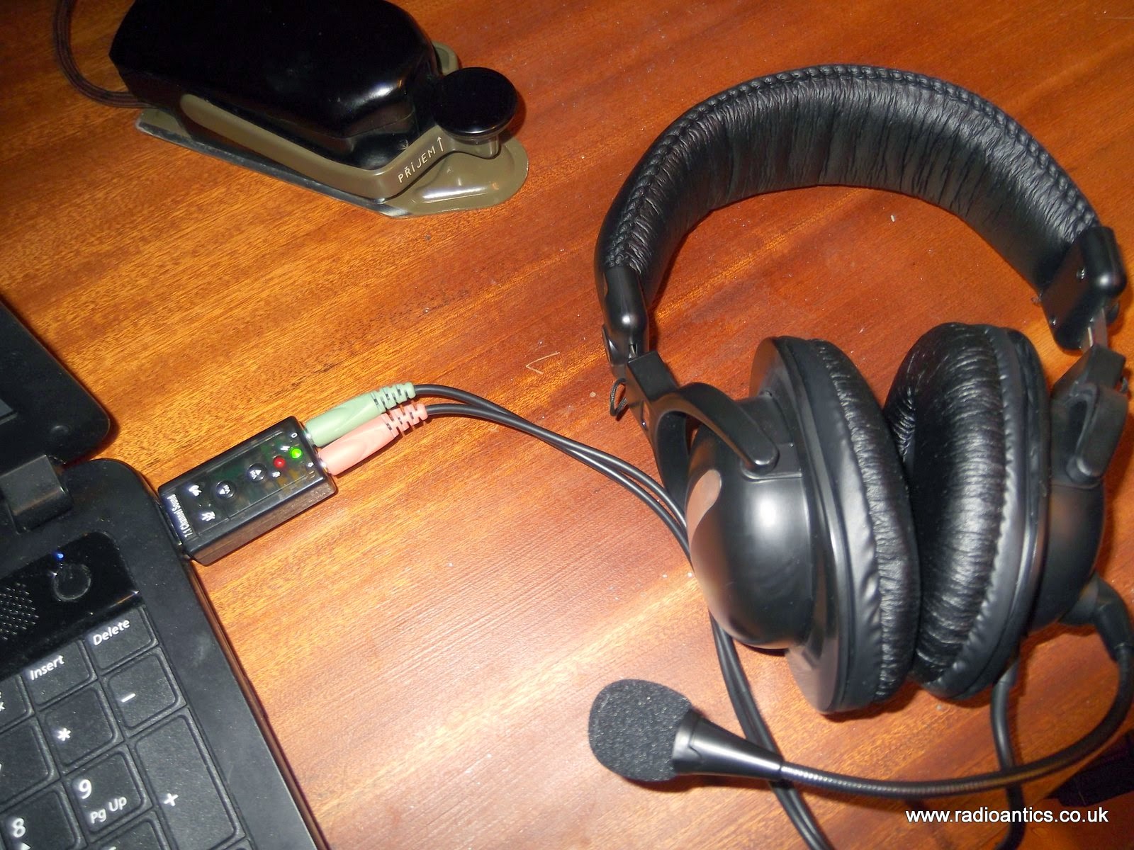
There is a lot of information. videos and guides available on the FreeDV website but the basics are straightforward. The computer requires two sound cards to handle the audio to and from the radio and the speaker/headphones and microphone. One method is to use a USB 'gamer' headset but since I already had a spare PC headset with 3.5mm plugs I opted for a cheap plug in USB soundcard (as detailed below)
Once the audio devices and PTT control are installed and configured within FreeDV it is a matter of monitoring a frequency (in USB) and hopefully you can send and receive.
So far I have only managed two QSOs with Trygve (LA6UOA) and Fabrice (F4FPG) on 14.236MHz with both the audio was clearly understandable but did suffer from the odd breakup and stutter. This was probably due to the laptop being used rather than an issue with the signal as the FreeDV needs a reasonably powerful machine with a decent amount of memory.
The software is very picky, several times the audio device settings have been forgotten or it has come up with a cryptic error message:
../src/msw/bitmap.cpp(846):assert "image.IsOk()" failed inThis is a known issue with the Windows version and the solution is to manually remove all of the FreeDV settings from the registry. The full details of how to edit the registry are in the GOTCHA section of the FreeDV site. Editing the registry is not recommended to the inexperienced person so is not a great solution and when starting the program backup after this fix requires reconfiguration of callsign, sound card and PTT settings again.
CreateFromImage(): invalid image
Despite this setback it is an excellent and exciting new mode. Both Trygve (LA6UOA) and myself were first timers when we had our QSO and we were like excited school children once we were able to converse successfully. Fabrice (F4FPG) was an old hand at it and I thank him for allowing me to briefly interrupt a QSO he was having with another UK operator who I could not hear.
I would recommend using K7VE's QSO Finder website http://qso.k7ve.org/ to see who is monitoring and on what frequency as well as passing hints in real time.
Datamode Interface built
To transmit and receive digital/data modes you need to connect the radio audio in/out to the computers sound card in/out, the computer then runs the necessary software to encode/decode the signals. I want to try out WSPR, PSK, JT65 and some SSTV for starters I have spent too long just receiving and decoding...
There are a number of inexpensive commercial interfaces available, but many of them use the same basic design originally intended for eQSO/Echolink operation. I nearly succumbed but I had built an eQSO interface many years ago when using PMR446 and had most of the parts to build another.
I nearly took the easy route and got a commercial one since connecting up some home built circuitry to a £20 hand held is slightly less daunting than plugging it into an expensive rig! My original interface has been modified and reused over the years and was a bit of a mess, but being brave I decided I could tidy it up and I couldn't really damage anything if I took my time... actually the truth was I discovered I didn't have the necessary optocoupler IC so couldn't build a new one just yet...
A simple internet search for digital/data mode interfaces will bring up a great deal of information, schematics and ideas for home brew solutions. The basics can be found here for example.
The simplest form of interface is just a simple direct lead with the transmitter operating in VOX mode. However levels can be a problem as the line/speaker output from a computer can be too high for a transmitters microphone input. Also connecting a radio to a computer directly can lead to problems with ground loops and interference.
The computer can be made to control the Push-To-Talk (PTT) on the transmitter using a serial port with the software controlling one of the handshake lines (RTS/DTR) Some data mode software support CAT to allow control of the PTT as well as tuning the transmitter, but the serial port method is more universal.
The preferred interface, and the one I had built isolates the computer from the radio by using two audio transformers and an optocoupler. There is no direct connection between the two devices so keeps interference to a minimum.
I could have used the microphone and speaker output on the radio, but the FT-857D has a convenient data connector on the back. This is a 6-pin DIN socket as used by older (PS/2) computer keyboards/mice. Note the diagram shown in the FT-857D manual (as below) is the view as you look at the socket.
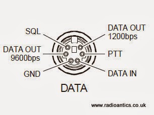 |
| FT-857D Data connector as in the manual |
Like many people I initially thought I could cut a lead off a mouse/keyboard and repurpose it, however I discovered most only use four wires and they don't use the necessary pins! You might be lucky especially with older keyboards or alternatively if you have an old keyboard extender cable they usually have all six wires present. Alternatively the plugs are readily available from the likes of CPC/Farnell.
I had a hunt around in a junk box and located a suitable keyboard extender cable. I chopped off the useless end and metered out the pins to identify the appropriate wires. Remember when looking at the plug the pins are swapped left-to-right compared to the diagram which is the socket view.
Well here is the insides of the interface.. and as you can see I completely failed to tidy it up! Not my best work, but I did put it in a new box and I did tape up all those unused wires!
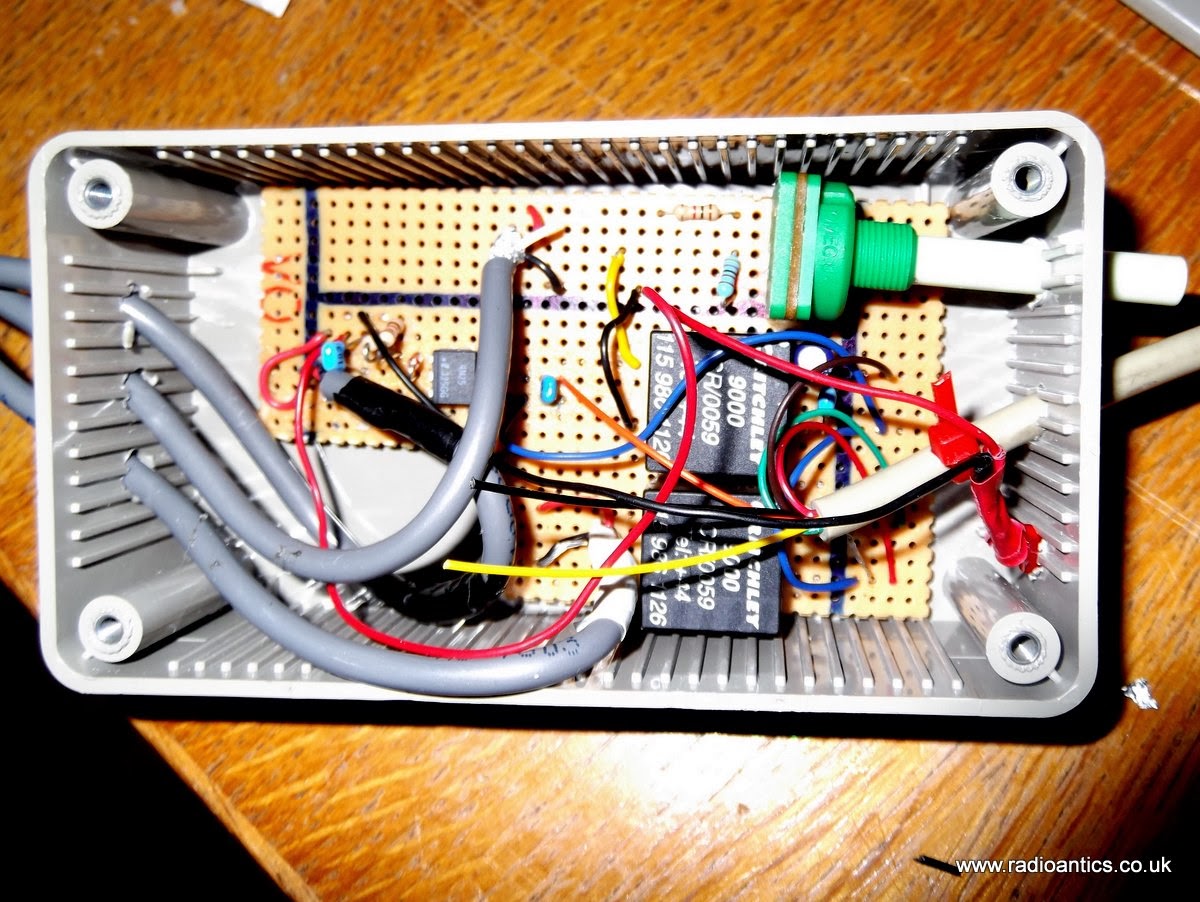 |
| The messy internals of the interface |
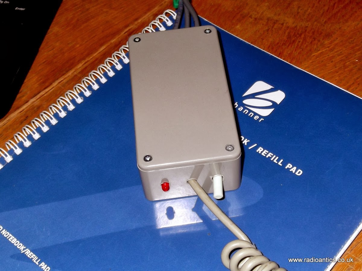 |
| It looks better with the lid on.. |
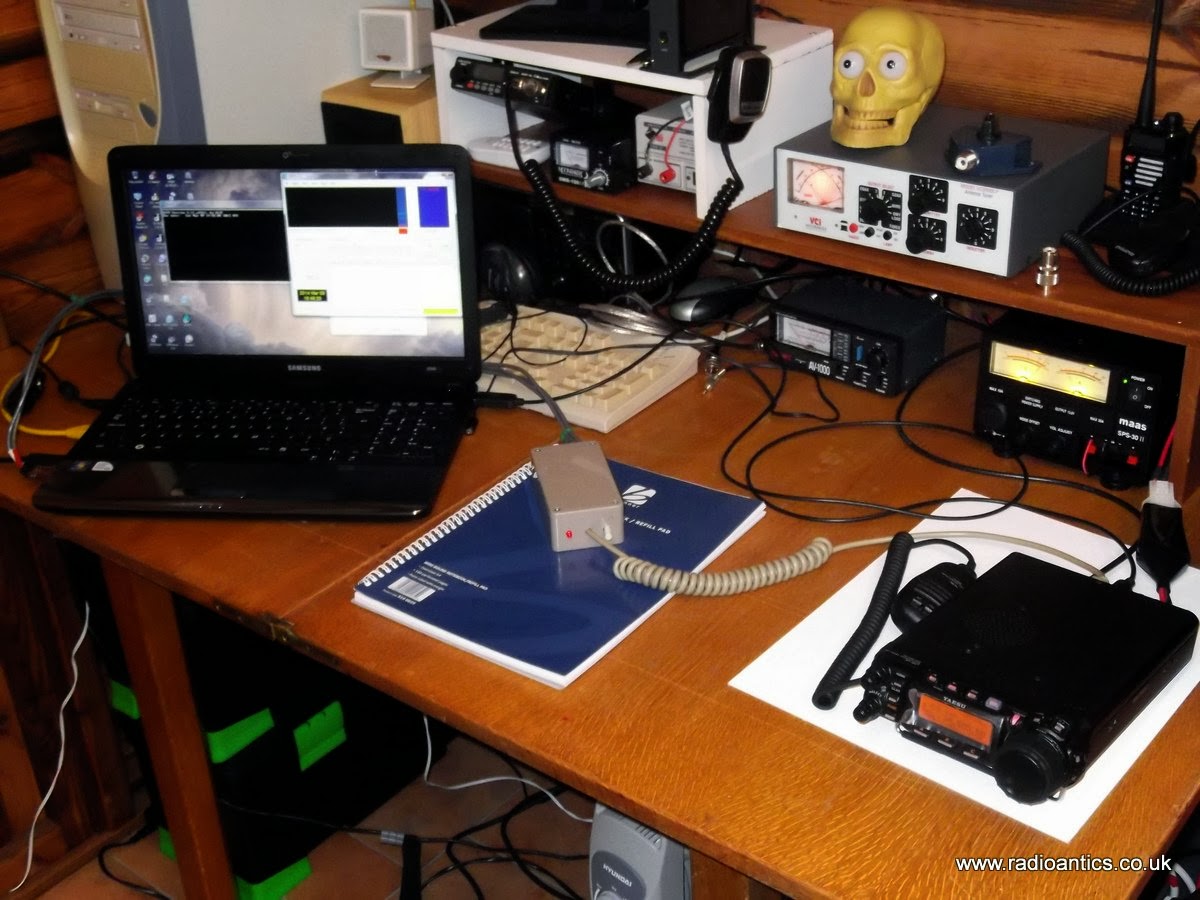 |
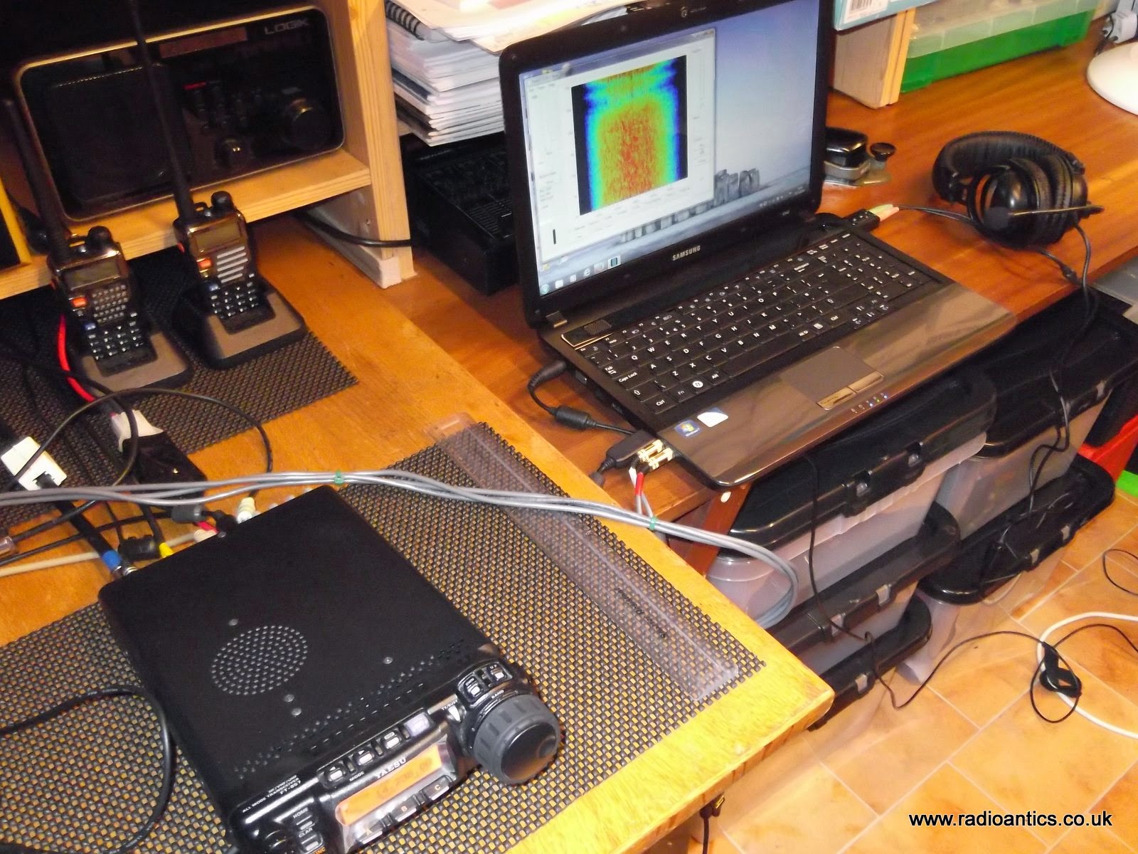
| Computer, radio and interface |
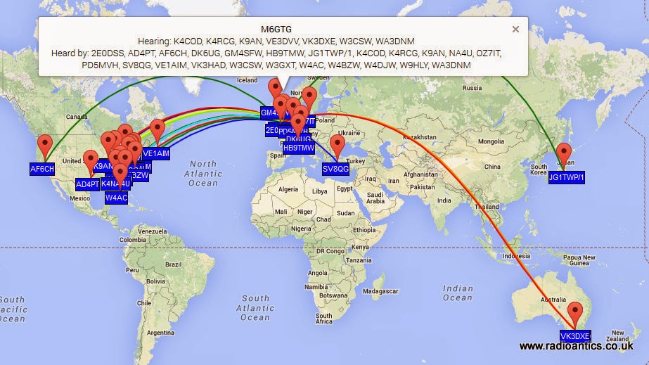
It was straight forward setting up WSPR to use a combination of CAT for tuning and the RTS PTT control and soon had some encouraging results, in fact these are some of the spots of my 5W signal on 10m/20m and 30m, I was grinning from ear to ear!
 |
| 10M Spots |
 |
| 20M Spots |
 | |
| 30M Spots |
Looking forward to spending some more time experimenting with the data modes.
6m PSK
I don’t often look for PSK warbles on 6m but am glad I did this evening. Obviously others were looking for someone as well I1YTO and I ended up having a brief QSO before he faded away again, up to 599 then down to nowt in a matter of seconds. Nice whilst it lasted


