Posts Tagged ‘Construction’
 Prop drift uncovered
Yesterday I wrote that I was shelving the Propeller beacon project after discovering that the frequency stability is unacceptabe. Eldon WA0UMH persuaded me to try some tests to identify the cause of the drift. My conclusion is that it is a combination of factors.
The major factor causing the drift is the power supply voltage. Whilst developing the beacon using just the Gadget Gangster board I was powering it with a 6V supply – the minimum needed. After adding a PA I needed to increase the supply voltage to 9V. The drift is greater with 9V, regardless of whether the PA is actually connected.
| Looking down on the Propeller board |
If you look down at the Gadget Gangster Propeller USB board there are two SMT chips to the left of the Propeller and its clock crystal which appear to be voltage regulators. There is a 5V regulator a few millimetres to the left of the 10MHz crystal and a 3.3V regulator below it. The greater the supply voltage, the more heat the 5V regulator has to dissipate. Plugging the LCD UI board on top of the Propeller board traps in more of that heat making the drift even worse. This is not the first time I have discovered that voltage regulators and crystal oscillators don’t go well together.
Whilst it is useful to know what is causing the drift, my discovery has not indicated an easy solution. Either I use a temperature compensated 10MHz crystal oscillator as suggested by one of my readers, or I use the Prop to control an outboard and more stable synthesized oscillator. The first option looks the easiest, but the TCXO is not an inexpensive component.
A Ham Shack Update
For many who follow this blog, you’ve known me for about as long as I’ve been licensed (almost 5 years). Unfortunately, during a large portion of this time I’ve been talking about the work I’ve been doing on my new ham shack, home office and man cave. If memory serves me, I began framing the unfinished portion of the basement in 2008.
I worked pretty much every weekend (and some evenings) and managed to get the 2×4 framing done in about 4-6 weeks. Then a few more weeks I had all the electrical, network, coax for CATV and telephone all done. I also had to do some plumbing work to move the washing machine hot/cold lines and drain down a foot or two. Then I stopped working on the project.
Weeks turned into months and months turned into a few years. Some of these delays were trying to decide what sort of wall material to use (sheetrock or paneling). The decision was made on sheetrock but then we kicked around whether we would do this ourselves or have it done. Finally we came to the conclusion we would continue with our plans of doing all the work ourselves.
So just after the new year I began working on the project once again. I had a few more items to do before I was ready for the sheetrock. All these final items where checked off the checklist and last weekend we placed an order for the drywall material. The drywall was delivered today.
Many of you have asked for photos along the way and well I finally snapped a few showing the stud walls. The picture below is one corner of the main room that will make up my ham shack, home office and man cave. The room is 16 feet by 16 feet. (I’m actually finishing out a much larger area than just the ham shack/office area) This corner will be my main operating position. The wall to the right is 8 feet and the wall to the left is 16 feet. I will install cabinets above and some below with countertop for the desk surface.

I’ve been working in a corner type setup for the past several years and actually prefer it. To my right will be my Yaesu FT-950 for SSB operation and to the left will be my Yaesu FT-897 which is setup for digital modes. My LCD computer screen will be positioned in the middle.
The picture below shows the above mentioned 16’ wall (this wall to my left). Again this will have some cabinets above and some above with work surface to the end.

I’ve tried to think of everything I would need not only today but in the future. Again this space will serve both as my ham shack and my home office. I also plan to have a nice TV and surround sound setup for when watching those action movies and sporting events. So I’ve pulled extra coax for CATV as well as extra network cables.
I plan to start hanging the drywall tomorrow (Saturday) after I move it down into the basement area. My rough goals are to have the drywall done by the end of March and perhaps painting done by end of April. We’ll see…
Until next time…
73 de KD0BIK
Propeller programming problems
Eldon WA0UWH posted yesterday on lessons learned about the Parallax Propeller programming language Spin. I too have been having fun and games trying to create a user interface for my multimode multiband beacon using the LCD module. Whilst some of my problems have been due to my failure to spot my own stupid mistakes, a couple were caused by the tools themselves.
A considerable amount of time was wasted recovering a working program after a change I made seemed to have messed it up. Eventually I discovered by accident that the program fails to run correctly on the Propeller board unless the main Spin source file is the foremost one in the Propeller Tool editor. I had begun splitting my code into separate objects with their own source files and because I had been editing or referring to one of these files I had tried running the code with one of these files in the foreground instead of the main one.
I wasted a couple of hours trying to backtrack what I had done and ended up installing one of those programs that archives each version of a file whenever you save it so that you can roll back to a previous state. The best program I have found for this is AJC Active Backup which comes with a diff tool that shows the differences between two files but unfortunately I have lost the licence key since the last time I installed it so as I was feeling tight-fisted I had to use something less good.
The other problem that caused a lot of lost time was an apparent error in the LCD UI Spin object. Specifically, the cursor method that is supposed to let you change the cursor to a flashing underscore or block just seems to clear the LCD and then crash. I had been hoping to use the cursor to show what bit of information the user was editing but I can’t get it to work.
I’m not sure exactly where I am going with the beacon project. Jeff KO7M has developed a WSPR encoder that generates the required code when you input your call, power and locator. However there is not much point in using it unless I provide an interface that allows you to input this information as text. If I choose to support Opera then the bit code will have to be programmed in as no-one other than Opera’s programmer knows the algorithm used to encode the callsign. As my beacon is unlikely to be used by anyone other than G4ILO in IO84 at however much dBm it produces I may as well hard code all beacon texts.
The other thing I’m not sure about is how to add the PA. The LCD UI module is now plugged into all the headers on the Gadget Gangster board and I don’t want to attach wires to the board itself. I could solder headers to the two rows of holes adjacent to the existing headers on the Gangster board and then plug a board to the bottom of it. That would be the probably be the neatest solution – unless anyone has a better idea?
Propeller crash
Yesterday I had another of those days that nearly made me decide to hang up my soldering iron for good. Some readers may have spotted the despondent blog post I made before I deleted it.
I assembled the Propeller LCD UI module. It went together easily and I had no trouble with the soldering using a magnifying lens (a strong pair of clip-on reading glasses clipped on to my normal reading spectacles) and resting my soldering hand on the desk to stop the shakes. But Murphy was not going to let me get off that easily.
Preparing to test the UI board I realized that I had skipped a page of the instructions and had not soldered a connector to the LCD daughter board. I thought that a connector for the main board (a male 8 x 2 box header) had been omitted from the kit so I had installed one of my own. When I picked up the daughter board I saw the two rows of 8 holes and without thinking installed the 8 x 2 plain header that came with the kit. Also male. When I realized my mistake bad words were said. In all my years of kit building I have never before done anything quite so stupid.
I recalled Don Wilhelm W3FPR’s advice to K2 builders who install multi-pin connectors on the wrong side of the board to sacrifice the connector and not try to remove it intact. This I eventually did with Olga’s help. She suggested I place the soldering iron body along the row of soldered joints to melt all of them so the connector would fall out. That didn’t work, but it did soften the plastic part of the connector allowing it to be pulled away. I could then remove each pin one at a time and clean up the through holes using one of Olga’s sewing needles. Finally I was able to install the four 1 x 4 female headers that had presumably been supplied with the kit as a replacement for an 8 x 2 female that was really needed.
After all that stress (both to me and the board) I was relieved that when I plugged it in to the Propeller board and ran the demo program the UI module worked. But my happiness was short-lived. After I tried some modifications to the program I found that it seeemed to be crashing. The program would start at switch-on but would eventually hand up and not respond to the buttons. Sometimes garbage appeared on the LCD. The time before this happened got shorter with each attempt until sometimes the Propeller wouldn’t even respond to the reset button. I restored the original program in case my changes were to blame, but the device was still crashing.
Next I re-heated all the solder joints I had made, though they all looked OK. On reassembly the Propeller still crashed. Thoroughly despondent by this point I typed a post describing what happened in the hope that someone would offer to come to my rescue (thanks to those who did.)
After a rest it occurred to me that I had crashed the Propeller by dropping the board a centimetre or so on to the desk. There was probably still a bad connection somewhere. I re-soldered all the joints, including all the ones on the main Propeller board. That had been ready assembled. I guess that the manufacturer had used lead-free solder because I couldn’t melt the joints until I applied a bit of my own leaded solder to each one. Then all the joints looked nice and shiny.
After that treatment everything worked and up until now, cross fingers and touch wood, has continued to do so. So it seems that a poor soldered joint in the manufactured board was the cause of my problem! Thank you, Murphy, but I don’t need your help. We do this for fun, do we?
Now output
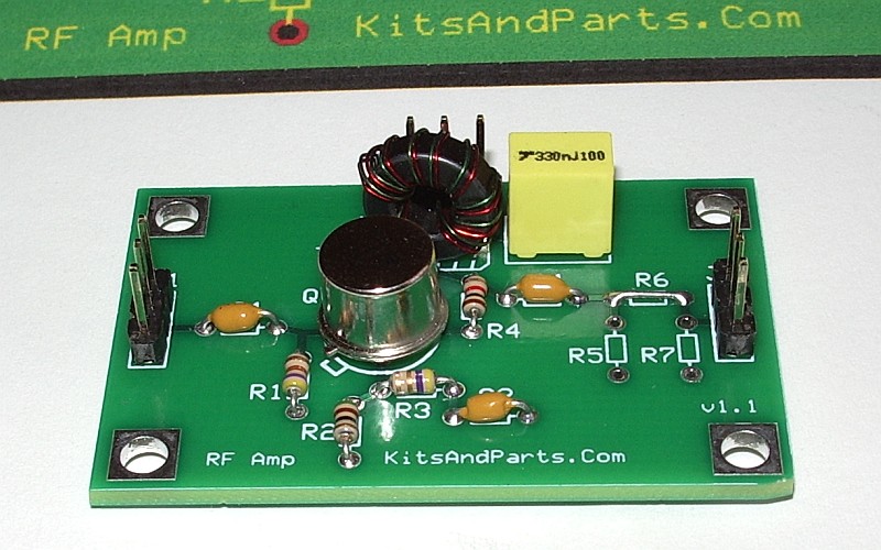
Everyone who commented to my last post about the lack of output from the Kits and Parts RF amp felt that the problem had to be the QRPer’s curse – the toroid inductor. Normally I don’t have a problem with toroids, but when they are so small that your thumb obscures the whole core while you are holding it, never mind winding it, they are not the easiest of components to work with.
So I gritted my teeth, tried to forget the hour I’d spent yesterday wrestling the thing into position, and yanked it out. One of the wires broke off in the hole leaving nothing to grab on to. I was unable to clear the small plated-through holes in any case. What I was able to do was melt the solder enough to push some bare wire through, creating “pins” that I could solder to. I twisted together the two wires that are connected so I had three ends to solder to the three pins I created. The toroid now stands up on the board a bit but it was easier soldering to the pins than trying to get four thin wires to go through four holes simultaneously. To my joy, on applying power and RF the power meter showed output.
I’m getting about 150mW if the amp is supplied with the recommended 8V, and just about 200mW from a 9V supply. That’s only about 10dB of gain, a bit less than expected but probably enough given that the Propeller does not generate the purest of signals. The WSPR beacon has already been spotted a few times in Germany. But the 2N5109 runs a bit hot to the touch so I’ll have to QRT until the heatsink I ordered arrives. In the meantime I still have the LCD UI board to assemble and play with.
No output
I built the Kits and Parts RF Amplifier. Unfortunately it didn’t work.
When power is applied the meter in my bench power supply reads 0.01A. As soon as the Propeller beacon starts the current draw increases to 0.03A (at 8V). But the needle on my QRP power meter, which shows more than 25mW from the barefoot Propeller, doesn’t budge.
I don’t understand it. It’s a simple enough circuit, there isn’t anything to go wrong. Unfortunately I find these kit construction failures too demoralizing. I struggle with my vision and shaky hands just to build the board. Desoldering and faultfinding are beyond me at the moment. If I do discover the cause of the problem it’s something really obvious that anyone with a normally functioning brain would spot. I think it is time for me to accept my limitations and stop attempting to do what I used to be able to do before my brain surgery. From now on if I can’t buy what I want ready to go out of the box I’ll just have to do without.
Under the microscope
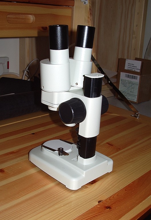 A couple of weeks ago Jeff KO7M wrote that he had acquired a binocular microscope for the workbench to enable him to work with SMT components. Although I have no particular desire to do SMT work at the moment I do have trouble with close-up work due to my eyes’ limited focal range and becoming very far-sighted. So I thought a binocular microscope would be a good addition to my workbench too.
Jeff wrote that his binocular microscope was not cheap and from the look of it I would imagine the cost ran well into three figures. The one I got was £30 from a firm that disposes of liquidated stock on eBay. I’m sure it isn’t as good as the one Jeff got but hopefully it will be useful. If not I can always start another hobby looking at plants and insects or growing bacteria!


