Posts Tagged ‘Audio’
 From Lightning Comes a New Icom IC-7610 (First Transmission)
Wow. What a radio!
One of the most useful (and, to me, amazing) features of this Icom IC-7610, is the IP+ function, which, when turned on, improves the Intermodulation Distortion (IMD) quality by optimizing the direct sampling system performance. This function optimizes the Analog/Digital Converter(ADC) against distortion when you receive a strong input signal. It also improves the Third-order Intercept Point (IP3) while minimizing the reduction of the receiver sensitivity.
In short: I was listening to an s-0 (i.e., no strength-meter movement) weak signal of a DX station, when right adjacent to the frequency came an s-7 signal, wiping out my ability to copy that weak signal. I turned on the IP+ and the distortion of the adjacent signal disappeared, and once again, I heard the weak signal IN THE CLEAR! WOW!
This video is a quick capture of my running the Olivia Digital Mode on HF, on the 30-Meter band. The transmissions are of a two-way Olivia digital-mode radio conversation between station K8CJM and station NW7US on 12 November 2019 (UTC date). K8CJM is located in Dayton, Ohio, and I am located in Lincoln, Nebraska. I’m running the radio at full power. The radio is rated as being able to handle 100% duty cycle at full power. The radio ran cool, no significant heating.
A few months ago, a lightning strike took out my ham radio station. The antenna was NOT connected, but I did not unplug the power supply chain and my computer from the wall. The surge came in through the power mains, and fried my uninterruptable power supply, the interfaces between my PC and radio, and fried the radio. Thankfully, all of that was covered by my homeowner’s insurance policy, less the steep deductible. My insurance covered all of the blown items, and that provided me this chance to obtain a repack version of the Icom IC-7610. I bought an extended four-year warranty.
CAUTION: Check the documentation of your transceiver/transmitter. NEVER run your radio’s power out at a level that exceeds what it can handle in reference to the duty cycle of the mode you are using. Olivia, for instance, is a 100-percent duty cycle mode. Morse code is NOT quite 100% duty cycle. Nor is SSB, a mode that operates with a duty cycle much lower than 100%. Your radio’s manual should tell you the specifications regarding the duty cycle it can handle! If you run more power than your radio can handle with the given duty cycle of the mode in use, you will blow your radio’s finals or in some other way damage the radio! Beware! I’ve warned you!
Compression and ALC!?
Some have noted that it appears that I’ve left on the Compression of the transmitted audio. However, the truth is that compression was not being used (as is proof by carefully taking note of the zero meter movement of the Compression activity). I had the radio set for 20-Meter USB operation on the Sub VFO. Compression was set for standard USB operation. Note also that the radio was transmitting USB-D1, which means the first data/soundcard input to the radio.
Also, some people complain about my use of ALC, because, in their view, ALC (automatic level control) is a no-no for data modes.
The notion that one must NEVER use ALC when transmitting digital modes is not accurate.
Multi-frequency shift keyed (MFSK) modes with low symbol rate–such as the Olivia digital modes–use a single carrier of constant amplitude, which is stepped (between 4, 8, 16 or 32 tone frequencies respectively) in a constant phase manner. As a result, no unwanted sidebands are generated, and no special amplifier (including a transmitter’s final stage) linearity requirements are necessary.
Whether the use of ALC matters or not depends on the transmitted digital mode.
For example, FSK (Frequency-Shift Keying; i.e., RTTY) is a constant-amplitude mode (frequency shift only). In such a case, the use of ALC will NOT distort the signal waveform.
PSK31 does contain amplitude shifts, as an example, therefore you don’t want any ALC action that could result in distortion of the amplitude changes in the waveform.
On the other hand, the WSJT manual says that its output is a constant-amplitude signal, meaning that good linearity is not necessary. In that case, the use of ALC will NOT distort the transmitted signal-amplitude waveform. You can use ALC or not, as you choose when you run WSJT modes, or Olivia (MFSK).
Clarification
Nowhere in this am I advocating running your audio really high, thinking that the ALC will take care of it. I am not saying that. I am saying that some ALC is not going to be an issue. You MUST not overdrive any part of the audio chain going into the transmitter!
Transmit audio out of the sound card remains at a constant amplitude, so there will be no significant change in power output if you adjust your input into the radio so that the ALC just stops moving the meter, or, you can have some ALC meter movement. You can adjust your audio to the transmitter either way.
If the transmitter filters have a significant degree of ripple in the passband then you may find that RF power output changes with the selected frequency in the waterfall when there is no ALC action. Allowing some ALC action can permit the ALC to act as an automatic gain adjustment to keep the output power level as you change frequencies.
Linear and Non-Linear
Regarding linear and non-linear operation (amplifiers, final stages): While a Class-C amplifier circuit has far higher efficiency than a linear circuit, a Class-C amplifier is not linear and is only suitable for the amplification of constant-envelope signals. Such signals include FM, FSK, MFSK, and CW (Morse code).
If Joe Taylor’s various modes (in WSJT software) are constant-envelope signals, than class-C works, right? At least, in theory.
Some Additional Cool History
The digital mode, Thor, came out of DominoEX when FEC was added. Here is an interesting history of FSQ that seems to confirm that FSQ is like MFSK, so no problem with a bit of ALC.
The following is from https://www.qsl.net/zl1bpu/MFSK/FSQweb.htm
History – Let’s review the general history of Amateur MFSK modes. The first Amateur MFSK mode developed anywhere was MFSK16, specified by Murray Greenman ZL1BPU, then first developed and coded by Nino Porcino IZ8BLY in 1999. Before MFSK16 arrived, long-distance (DX) QSOs using digital modes were very unreliable: reliant, as they were, on RTTY and later PSK31. MFSK16 changed all that, using 16 tones and strong error correction. Great for long path DX, but nobody could ever say it was easy to use, never mind slick (quick and agile)!
Over the next few years, many MFSK modes appeared, in fact too many! Most of these were aimed at improving performance on bands with QRM. Most used very strong error correction, some types a poor match for MFSK, and these were very clumsy in QSO, because of long delays.
The next major development, aimed at easy QSOs with a slick turnaround, was DominoEX, designed by Murray Greenman ZL1BPU and coded by Con Wassilieff ZL2AFP, which was released in 2009. Rather than using error correction as a brute-force approach, DominoEX was based on sound research and achieved its performance through carefully crafted modulation techniques that required no error correction. The result was a simpler, easier to tune, easily identified mode with a fast turn-around.
DominoEX is widely used and available in many software packages. A later development by Patrick F6CTE and then Dave W1HKJ added FEC to this mode (THOR) but did not add greatly to performance, and at the same time eroded the fast turn-around. The final DominoEX- related development was EXChat, a version of DominoEX designed specifically for text-message style chatting. While completely compatible with DominoEx, it operates in ‘Sentence Mode’, sending each short over when the operator presses ENTER. EXChat was developed by Con ZL2AFP and released in 2014.
Back in 2013, Con ZL2AFP developed an MFSK mode for LF and MF which used an unusual decoding method pioneered by Alberto I2PHD: a ‘syncless’ decoder, which used a voting system to decide when one tone finished and another began. The first use of this idea was in JASON (2002), which proved to be very sensitive, but very slow, partly because it was based on the ASCII alphabet. The new mode, WSQ2 (Weak Signal QSO, 2 baud) combined the syncless decoder with more tones, 33 in total, and an alphabet specially developed by Murray ZL1BPU, which could send each lower case letter (and common punctuation) in just one symbol, resulting in a very sensitive (-30 dB SNR) mode with a 5 WPM typing speed.
In the subsequent discussion in late 2014, between the developers ZL2AFP and ZL1BPU, it was realized that if the computer had enough processing power to handle it, WSQ2 could be ‘sped up’ to become a useful HF chat mode. This required a large amount of development and retuning of the software to achieve adequate speed was involved, along with much ionospheric simulator and on-air testing used to select the most appropriate parameters.
Tests proved that the idea not only worked well, but it also had marked advantages over existing HF MFSK modes, even DominoEX. As expected, the new mode was found to have superior tolerance of signal timing variation, typically caused by multi-path reception, and would also receive with no change of settings over a wide range of signaling speeds.
So this is how FSQ came about. It uses the highly efficient WSQ character alphabet, IFK+ coding, the same number of tones as WSQ (33), but runs a whole lot faster, up to 60 WPM, and uses different tone spacing. The symbol rate (signaling speed) is modest (six tones per second or less), but each individual tone transmitted carries a surprising amount of information, resulting in a high text transmission speed. And it operates in ‘Chat’ (sentence) mode, which allows the user to type as fast as possible since they type only while receiving.
The ability to send messages and commands selectively has opened a huge array of communications possibilities.
What Makes FSQ Different
Incremental Keying – FSQ uses Offset Incremental Frequency Keying (IFK+), a type of differential Multi-Frequency Shift Keying (MFSK) with properties that make it moderately drift-proof and easy to tune. IFK+ also has excellent tolerance of multi-path reception.
IFK was developed by Steve Olney VK2XV. IFK+ (with code rotation) was proposed by Murray Greenman ZL1BPU and first used in DominoEX. IFK+ prevents repeated same tones without complex coding and provides improved rejection of propagation-related inter-symbol interference. In the context of sync-less decoding, the IFK+ code rotation also prevents repeated identical tones, which could not have been detected by this method.
Efficient Alphabet – In FSQ, a relatively high typing speed at a modest baud rate comes about because the alphabet coding is very efficient. All lower case letters and the most common punctuation can be sent in just one symbol and all other characters (the total alphabet contains 104 characters) in just two symbols. (The alphabet is listed below). This is a simple example of a Varicode, where it takes less time to send the more common characters. The character rate is close to six per second (60 WPM), the same as RTTY, but at only 1/8th of the baud rate. (RTTY has only one bit of information per symbol, 7.5 symbols per character, and wastes a third of its information on synchronization, and despite this, works poorly on HF).
No Sync – Another important factor in the design of FSQ is that no synchronizing process is required to locate and decode the received characters. Lack of sync means that reception is much less influenced by propagation timing changes that affect almost all other modes since timing is quite unimportant to FSQ; it almost completely eliminates impulse noise disruption, and it also contributes to very fast acquisition of the signal (decoding reliably within one symbol of the start of reception). Fast acquisition removes the need for the addition of extra idle characters at the start of transmission, and this leads to a very slick system. Add high resistance to QRM and QRN, thanks to the low baud rate, and you have a system so robust that it does not need error correction.
Cool.
See you on the bands!
Your Opinion, Please (first of several)
I am asking for opinions on audio, in my videos. I am in the process of choosing the better of several mics. Right now, I have two comparisons. One is a lapel mic. One is a headset boom mic.
Your opinion is appreciated on the best of two microphones used in upcoming videos I hope to create on my channel on YouTube ( https://YouTube.com/NW7US ), during those times when I want to vlog from my moving vehicle.
I am assessing several things: background noise level, clarity of voice, ease of understanding my words in context to background noise, and, ease of listenability–you know, I am seeking opinions on which of the two mics makes the audio pleasant and not fatiguing.
The two videos are listed here:
http://blog.nw7us.us/post/167110007307/i-need-your-opinion-please
Please leave a comment on your preference of one or the other mic, and why.
LHS Episode #144: Amateur Radio Resources
 Hello, folks! We're happy to say that Pete has rejoined our crew for this episode of the show, and he brings with him some excellent information for all you listeners out there. We take a look at several great video and audio resources for amateur radio adventures this fortnight. On top of that, we give a detailed description of YFKtest in action during a contest, and an overview and introduction to the latest version of the Tucnak logger. Lots more news, reviews and excitement as well. Please enjoy!
73 de The LHS Guys
Ham Radio Mystery
I wrote, produced, and recorded Cornbread Road, a ham radio mystery series in 2010 when it was released one episode per week for thirteen weeks. After a successful run, I removed the files from the server as I never intended it to be continuously available.
But ever since then I have made the thirteen audio files available once a year for a limited run — for those who might have missed it. The audio series is available again right now, but only until the end of the month. On Halloween I’ll pull down the files until next year. Download them now or wait until next year.
It’s all fun, fiction and unlike any ham radio story you’ve ever heard told.


Scratchy Tivoli Audio Model One
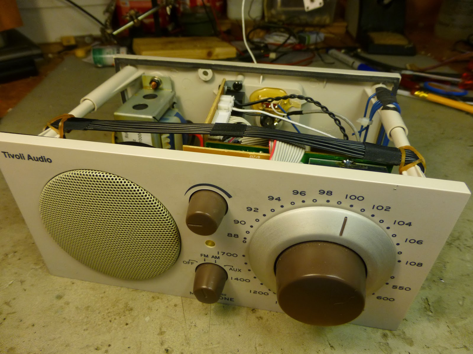
The Model One has been a huge success. But in many ways it is a daring retro design judging from all the features that are missing in this radio. I am thinking of features such as a customizable equalizer, a digital display, and memory presets. It just has a plain old analog tuning dial for FM and AM.
The radio could as far as I can tell just as well have been made in the 70’s except for some of the IC’s which are used. Actually it is easy to see the similarity with the even older KLH Model 18 from the 60’s, and yes – Henry Kloss played a role in both radio designs. But that makes for easy repairs, such as a seemingly common fault in the FM tuning capacitor, which over time may develop contact problems.
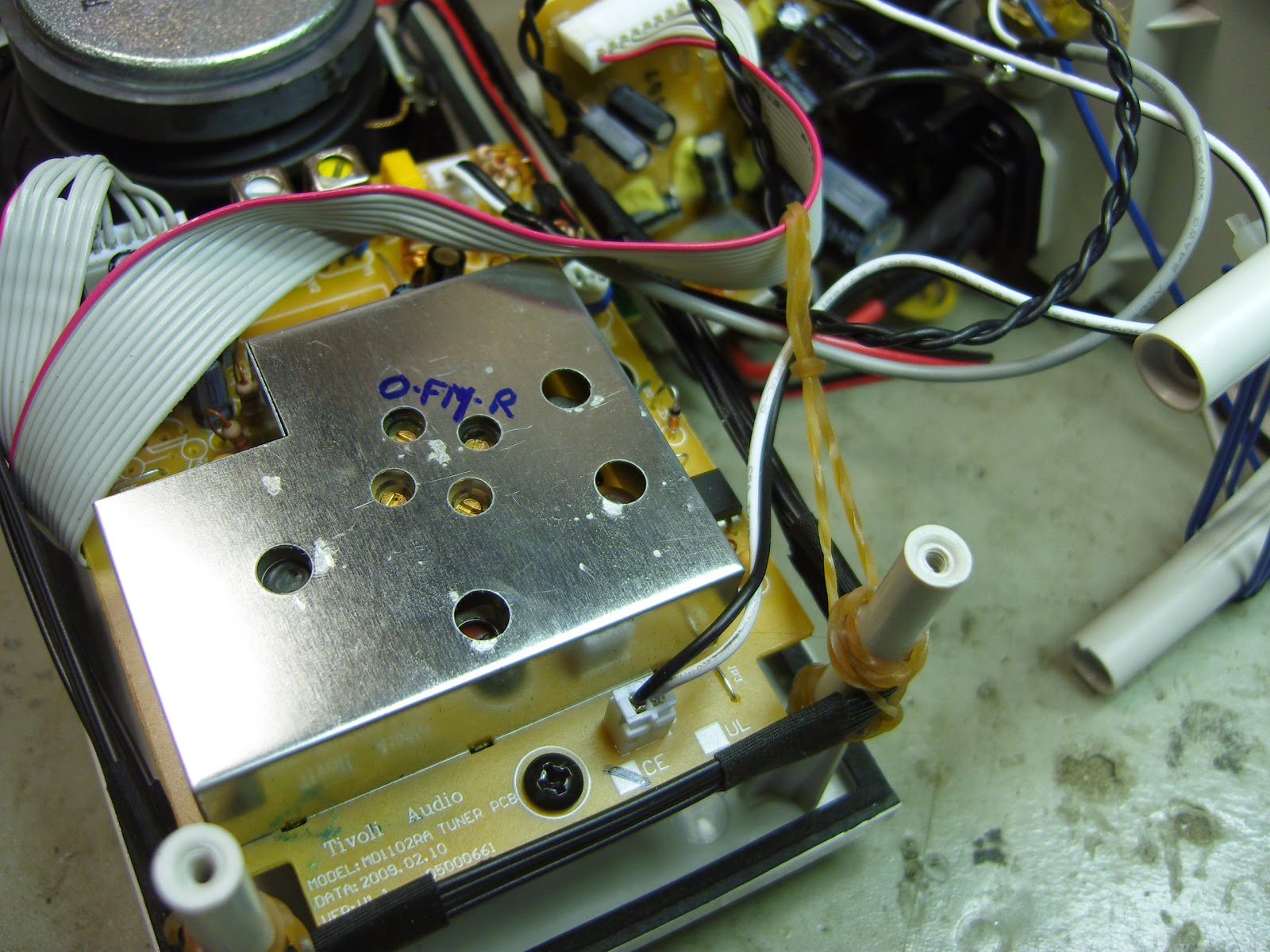
The radio is in many respects exceptionally well made. The tuning dial has a quality vernier drive. The audio section is well built with a powerful amplifier, a strong magnet for the loudspeaker, and a bass port design for the wooden cabinet. All are factors which contribute to its reputation for good audio. If one can trust measurements on the web, it has been equalized for enhanced bass and treble with the mid’s some 6 dB down. These are well-known tricks for getting a warm and crisp sound with universal appeal. Internally the tuner section, which is built around the TEA5711T chip, is well shielded for frequency stability as seen in image 2.
 One weakness which manifested itself after only 3-4 years in this particular radio is that it became hard to tune, scratchy, and unstable on FM due to intermittent contacts in the tuning capacitor. According to the TEA5711T datasheet it is a varicon which for AM has 140/82 pF, for FM 2 x 20 pF, and for trimmers 4 x 8 pF. This particular unit had a Mitsumi varicon. Some say, when this fault occurs, that the varicon must be replaced and others say it can be cleaned. Who do you think I sided with?
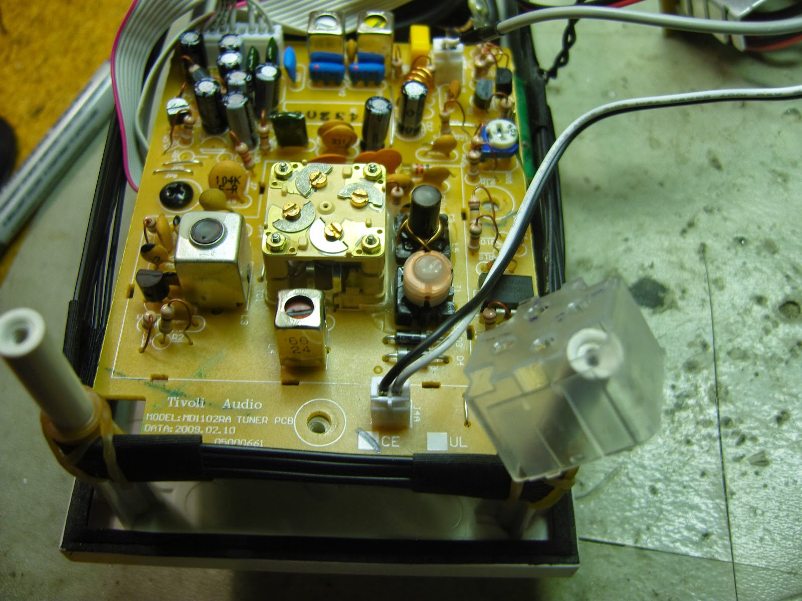
Disassembling the radio is quite straightforward if you are used to this kind of work. The tuner is enclosed in shielding on both sides of the PCB. The shields can carefully be desoldered as shown in image 3. That exposes the varicon, and its plastic casing can be lifted as shown in the last image.
 I sprayed it with contact spray and the radio came back to life. The only problem was that the tuning on FM had shifted so that a station on 100 MHz now appeared on 107 MHz. A little detective work around the circuit showed which trimmer that was for the FM oscillator and which one that was for the FM RF circuit (marked O and R in image 2). Since the oscillator trimmer was set for its maximum capacitance with the plates covering each other, it was easy to reduce the value and get the FM dial back to normal again, and then to peak the RF trimmer.
 It got me wondering though to see that it had been necessary in the first place to have the oscillator trimmer set at its maximum value. It was just as if the tuning capacitor never had had its full value, even in the factory, and that it finally got it after my cleaning.
The simplest possible AM transmitter
Here’s a design for a 1 MHz amplitude modulated (AM) transmitter. I’ve been looking a while for something like this, a simple short range AM transmitter for the medium wave band, as I needed something for demonstration of my collection of old radios.
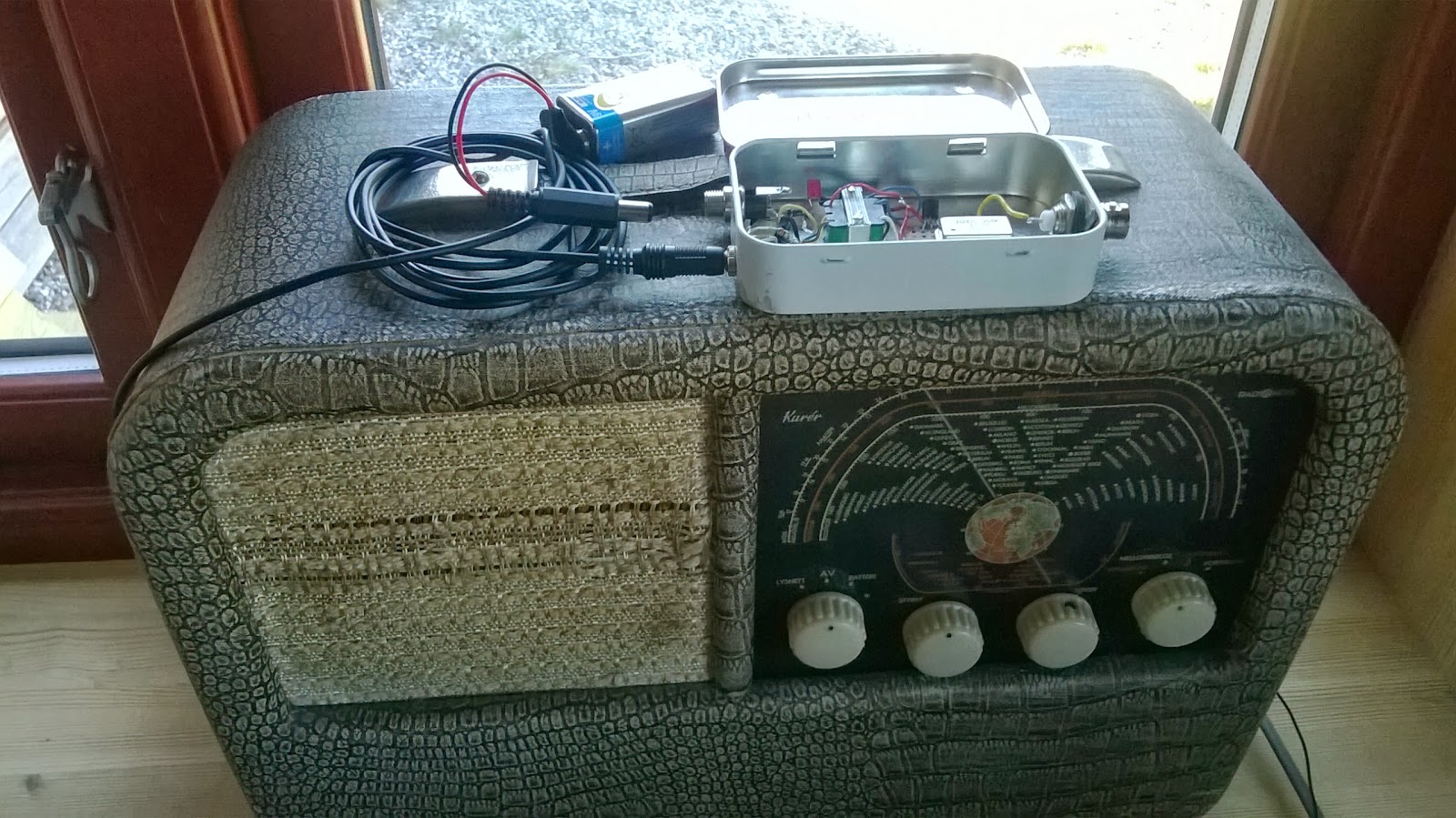
The result is the AM transmitter shown here in an Altoids tin on top of a Radionette Kurér radio. This is a portable tube radio from the 1950’s. Several hundred thousands were produced, and it was exported from Norway to 60 countries. It is still popular among collectors.
The transmitter is as simple as it gets. The heart of it is a 1 MHz crystal oscillator in a can. Its 5 Volt power is modulated via an audio transformer, one taken from the output of a transistor amplifier (primary 147 ohms – secondary 3 ohms). I drive the modulator from my cell phone into the low resistance side of the transformer and get good audio when the phone’s volume is set to maximum.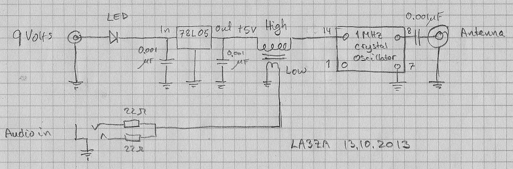
The design was inspired by one from Instructables, but mine also has a 78L05 5 Volt voltage regulator and a red LED in series with the power supply. It indicates that the battery is plugged in. In total the transmitter draws 4.4 mA at 9 Volts. The input power to the oscillator is less than 5 Volts * 4.4 mA or in the order of 20 mW. The power output is just a fraction of that. I have tested it with a 1.5 m wire hanging down behind the built-in frame antenna in the back of the radio with good results.
This is really just a modulated marker transmitter as I have briefly described on this blog before, and the square wave will have harmonics of 1 MHz over the entire short wave band. Some of these frequencies may propagate really well, so if used with a longer antenna, it should really have an output low pass filter to prevent that.
I’m not totally happy with this design, despite its simplicity, though. If I could, I would rather like to transmit in the long wave band at 216 kHz. This is the old frequency of the Oslo transmitter which ceased operation in 1995. As a member of the Norwegian Radio Historical Society, I am allowed to use that frequency with a transmitter input of 0.5 W for demonstration purposes.
For other frequencies, one simple alternative is a standard canned oscillator at 1.288 MHz. I also believe some of the Silicon Labs oscillators can be used in order to get an adjustable frequency, but I haven’t tried that myself.
But until I find a suitable frequency source at 216 kHz, I’ll stay with the 1 MHz alternative at a mere 20 mW. It is in line with the best principles of KISS (keep it simple stupid) or with Occam’s principle : “It is vain to do with more what can be done with less“, i.e. the QRP philosophy.
LHS Episode #105: Linux on the HamStack
 That’s right, we’ve got yet another interview in this show. Is anyone screaming “UNCLE!” yet? George from Sierra Radio Systems and Nick from Pignology are our guests tonight, talking about several of their ham radio related products. They have a product launch they’re doing at the Dayton Hamvention this year and wanted to let everyone know what they have in store so it’s out there before the chaos in Ohio. Don’t despair, howver. This is not a sales pitch. Instead, our fine feathered guests get down into the nitty gritty of their product, explaining what it does, how it does it, what hardware it uses and what software as well. You’ll be happy to know it’s all Free Software based and an incredible find for anyone looking for comprehensive remote station control. George and Nick also happen to be responsible for a significant chunk of the donation money LHS needed to be a part of Dayton this year so we are eternally grateful to them for that. The best part of all this: That’s only HALF of the show. This one’s so packed full of information it might just explode.
73 de The LHS Guys


