Posts Tagged ‘Antenna projects’
 Radiation pattern after adding radials.
The other day, I battled the heat and installed more radials for my Hustler 4BTV. I have an extra 14-gauge wire left over from when I first installed the radials, and for some time, I was planning to install the remainder, but never got around to it. Well, it is now done, and I am about 15 radials richer, bringing the total to close to 40. After the install, I was wondering if my radiation pattern has changed at all? I connected my WSPR transmitter over the period of 24 hours. For some reason, when I set it up, it was only sending signals out on 20 and 40m. I found out I neglected to save the settings, and the 20m and 40m setup was from the last time I used it. So I only have at this time data for those two bands.
Below are the patterns before the radial additions.


After the radials upgrade


Hustler 4BTV cleaning event.
My Hustler 4BTV has now been up for 5 years and is serving me very well, I might add. I felt it was time to take it down and clean it. I know, as Murphy would have it timed that something went wrong and it would be the middle of winter on a very cold and windy day. The items I used were a wire brush to get inside the tubing to clean, 99% alcohol for cleaning and a roll of 3M 33+ tape. This tape has a good temperature range. Finally, a Scotch Brite pad....which I never ended up using. I had read online that it was great for cleaning the aluminum tubing....found out not so much. It has been retired to the kitchen for pots and pans.

My plan was to take each section apart and clean it, and then back together again. I did not want to get too far ahead of myself by taking the whole antenna apart. Before taking a measure section of tubing apart, I measured it and also marked the tubing with a Sharpie marking pen. I wanted to take a measurement and mark it down just in case I removed the Sharpie mark while cleaning. Oh, speaking of cleaning, I thought the wire brushes would be great for cleaning the inside of the tubing, BUT....the 4BTV tubing is 1 1/4 diameter, and I used the 1 1/4 wire brush. The brush went into the tubing just fine, but the bristles refused to go in the opposite direction to bring the brush out! It did take me some time, but I did get the brush out and lesson learned. I used the 1-inch brush instead, which did a great job. All the traps looked great and were still nice and clean. The lower section of the tubing support needed some cleaning, as well as the section of tubing. Overall, for being up 5 years in the ocean air, the antenna looked great. The spider arm required the most cleaning, and I did find a broken spider arm. I do have replacements that I needed to drill a hole in, as I figured some time ago, the spider arms are the weak point of the antenna.
 |
| Top of spider arm |
 |
| Bottom of spider arm |
.JPEG) |
| Example of clean trap |
 |
| Damaged spider arm |
 |
| Inside tubing |
 |
| Base section before cleaning |
Read the rest of this entry »
It’s antenna farm time.
Before I purchased my Hustler 4BTV vertical antenna I was using a 45 foot End-fed antenna. I have kept the End-fed antenna coiled up and ready to go along with the coax still attached. The Hustler vertical only gives me 40, 20, 15 and 10m which is great for contesting BUT if I wanted to venture on to other bands it would mean using the End-fed antenna. Also during high wind storms or freezing rain, I have taken the Hustler vertical down and left with no antenna. I have been thinking of bringing the End-fed antenna back to life and using it when the Hustler is down due to weather and to venture on the bands the Hustler does not cover.
I rehung the End-fed antenna recently to run it through the paces with my antenna analyzer to make sure after sitting unused for so long there were no issues. It checked out just fine and the SWR was decent and where it was a bit high my trusty LDG AT-200pro II would look after it. The main obstetrical for me is the proximity of the two antennas when they are both up at the same time. My next test was to connect my End-fed antenna to my Daiwa CN-901 antenna port and a 50-ohm dummy load to the radio port. I then wanted to transmit 100 watts into my Hustler 4BTV antenna and see what type of reflected power the Daiwa CN-901 SWR meter was showing. Below are the results for 40, 20, 15 and 20m on the 20 watts scale.

40 Meters 
20 Meters 
15 Meters 
10 Meters
The reflected power was not significant and 10m was the highest. I plan to disconnect whichever antenna I am not using and connect it to a 50-ohm dummy load. In the future, I may prefab a 12-volt relay to switch between each antenna and use the relay contacts as the isolation point. For now, it is going to be the dummy load solution.
Part one: HOA antenna challenges.
 |
| Alpha Delta DX-EE |
Many Amateur radio ops now find themselves in a neighbourhood, downsizing to a condo or moving to an assisted living complex that is ham radio antenna unfriendly. I have lived in many antenna challenged, HOA and condo rules that outlaw antennas. But I have always managed to get on the air using HF and enjoy the hobby. Over the next few posts, I am going to share how I accepted the antenna challenge and kept the HOA hounds or condo cops from having their heads spin backwards. Today let's look at a situation that involves home HOA hounds or townhouse condo cops.
In the neighbourhoods I have moved to I always get a copy of the rules. (HOAs and condos have more pleasant words than rules) But let me start by saying I am not against having common understandings (rules) as it can control some funny things that can pop up in uncontrolled neighbourhoods or condos. In most of the rules I have read regarding antennas, it boils down to you can't have them due to safety, how they look and the size. The way I see it is if it's safe, no one see's it and it's small then we are good to go with an antenna!
The first big hurdle is out of sight, as with amateur radio an HF antenna can be a tough one. For 16 years I lived in a townhouse which was not antenna friendly. I found we had a very large attic and then the next challenge was what to put up there for HF operations. What I tried was 2 mobile whips configured into a dipole. This had a very narrow bandwidth and only a single band as I could not set up more than one due to space and interaction. A band change meant getting up in the attic and doing the whip change. That idea was deleted due to attic heat in the summer and just getting up and down from the attic.
 |
| Electric fence stand-offs |
My goal was a multiband antenna that was small and could be left in the attic and forgot about. I committed to a dipole antenna from Alpha Delta the DX-EE model. This was a 10-40m antenna that was 40 feet long. Now my attic is nowhere close to being 40 feet long but I ended up installing it in a "Z" configuration. To secure the antenna in the "Z" configuration I used electric fence standoffs. Also, I added a 1:1 choke balun at the antenna feed point. This antenna served me without issue for years and it was out of the elements from the weather, out of sight and got me on the air. As a sidebar, I only transmitted at QRP levels as I did not want to have any issues with those on either side of us in the townhouse.
 |
| DX-EE |
Some of the challenges were:
The antenna had a narrow bandwidth on 40m but the Elecraft K3 tuner looked after that. As well using the Elecraft K3 tuner I was able to also use the WARC bands as well.
I picked up very bad band noise from a Plasma TV but that was fixed with an MFJ noise-cancelling unit.
Getting the coax from the attic to the radio room. The room was on the second floor and I ended up putting the coax in the wall and out in the radio room.
Securing the antenna for a "Z" configuration. As mentioned I used electric fence stand-offs.
Getting the best bang for each watt of power meant CW and not SSB. That began my journey of re-learning CW. Also fast forward to now there is also the digital modes you can use.
The next post (part 2) will be dealing with my condo apartment antenna challenges.
Hustler 4BTV base cover.
 |
| Lower section before balun install. |
Autumn is here along with the leaves all over the lawn, once or twice a week I take the lawn mower out with the grass catcher on and vacuum the lawn of leaves. Doing this got me thinking of winter and my Hustler 4BTV antenna regarding the snow. I did some internet searches and some left the base alone while others covered it. The conscience was that snow does not bother the vertical with regards to performance but I was concerned about the connections and isolation balun.
I decided to make a box to cover the base section of the antenna but one that could easily come off in case of a storm and I had to lower the antenna. I wanted something simple, that would stand up to the weather and remove without issue. I came up with a cover made of wood and only 4 deck screws had to be removed to remove the box cover from the antenna for storage. The top also has 4 deck screws it can be removed for access to the antenna if it has to be taken down due to high winter winds.
I also made the box with room on the side as I knew I would be adding the choke balun to the mix. It's going to be painted white to mix in with the snow when it comes and I will keep on top of shovelling the snow on and around it just in case the antenna has to come down due to windy weather.
As said before to remove the box ultimately all that has to be done is 4 deck screws removed and the side cover and half of the top cover comes off and the box can be removed and stored for the summer. In case of poor winter weather, 2 deck screws are removed and half of the top cover is removed and the antenna base is exposed.
 |
| Room for the Balun |
 |
| Completed box to be painted |
The final picture shows 1/2 of the top cover removed and the lower screw clamp is exposed and can be loosened for the antenna to be removed. The cover goes back in place.

Read the rest of this entry »
New Antenna: The Following Footprints Are of My CW Signals (2021-March-14 @ 04:00 to 04:20 UTC).
The following footprints are of my CW signals on 2021-March-14 at about 04:00 to 04:20 UTC.
Click on this image to see a larger version of this image:
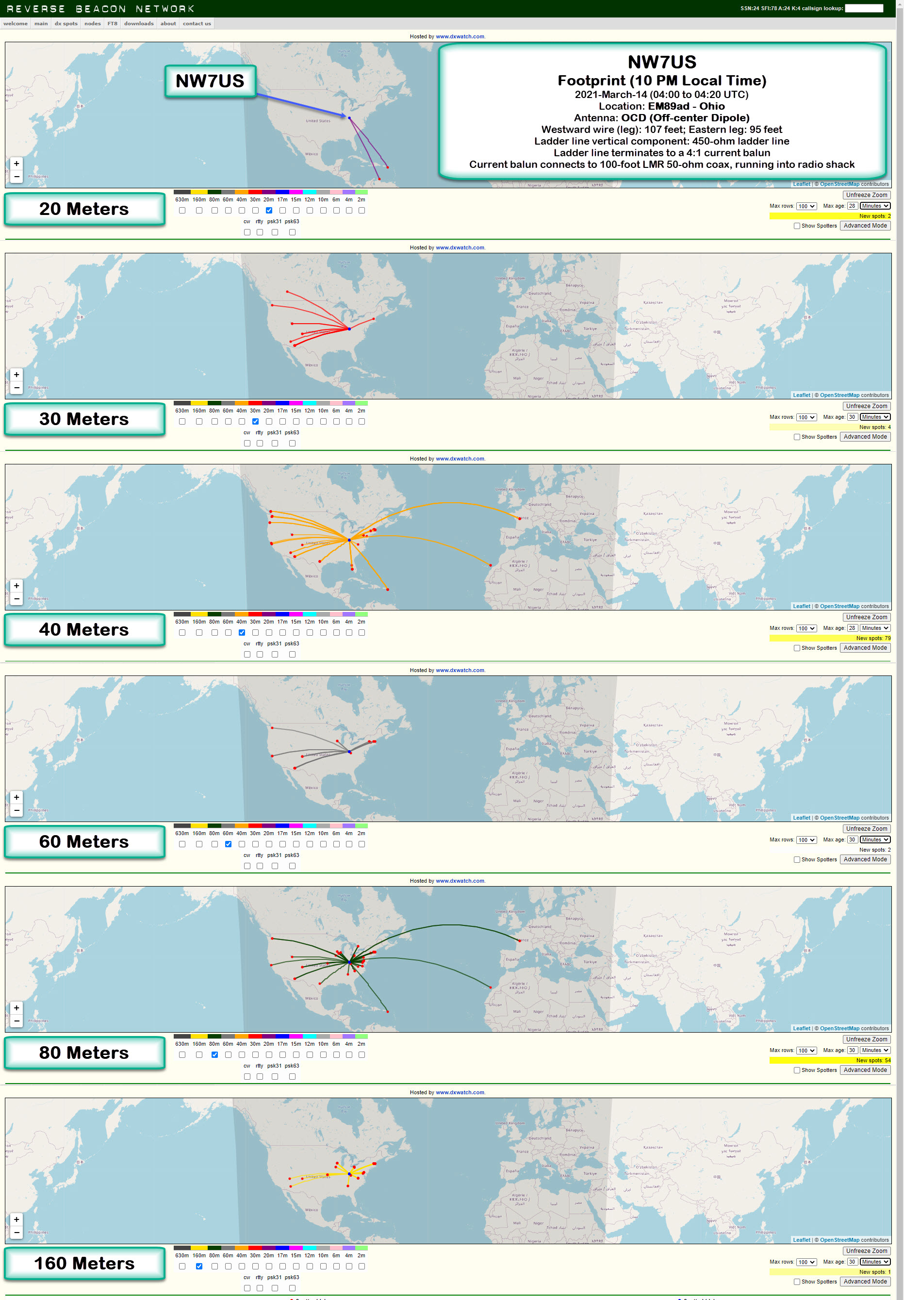
Location: EM89ad – Ohio
Antenna: OCD (Off-center Dipole)
Description of Antenna:
This is an off-center dipole, with the two legs running East-East-South (approximately 125 degrees of North), and West-West-North (about 306 degrees on the compass). The westward wire (leg) is approximately 107 feet in length, while the eastward leg is about 95 feet in length.
These legs (an off-center-fed dipole) is directly connected to about 90 feet of 450-ohm ladder line, which is hanging directly below, vertically, the feed point. The feed point is 50 feet above the ground.
The ladder line terminates (at the 12-feet-above-ground point) to a 4:1 current balun. This current balun then connects to a 100-foot LMR 50-ohm coax, which is running into the radio shack. It is connected via an antenna switch to my Icom IC-7610 transceiver. I am transmitting a 100-watt CW signal using an Icom IC-7610, in the following format:
TEST TEST TEST DE NW7US NW7US NW7US
The Reverse Beacon Network reports any spotting of this test transmission. The beta mapping interface, at http://beta.reversebeacon.net/main.php, then maps the resulting spots. To learn more about the RBN, visit http://beta.reversebeacon.net/index.php, or, http://reversebeacon.net/index.php.
I show the 20-, 30-, 40-, 60-, 80-, and 160-Meter band footprints.
I’ve been capturing these CW transmission spots, at different times of the day, today. I’ll get data from several days, at regular intervals, and create a overview of how the antenna appears to be working during this month and under these propagation conditions.
73 de NW7US dit dit
..
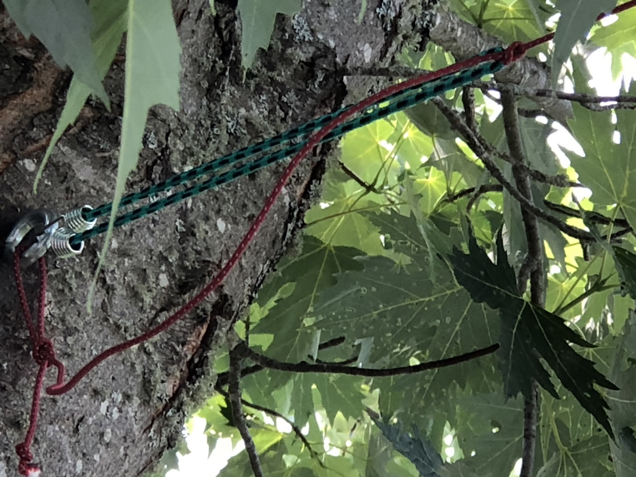
Tweaking the Endfed antenna.
 |
| Three feet of wire |
With the counterpoise attached, I went into the shack and ran through the bands using my MFJ 259B antenna analyzer and recorded the results and then once again with the counterpose removed. As a side note, one of the best purchases I made was the antenna analyzer, it makes short work of most antenna testing tasks. I do have a second antenna analyzer which is the Funk FA-VA4 its a nice unit but because its menu-driven I find it to be a bit cumbersome. With the MFJ unit, you select the band range with one knob and with the other knob spin to your desired frequency and then read the LED readout.
Well back to the Endfed experiment and below are the results with the added 3 feet of wire.
Results without a counterpoise:
Band Freq SWR
- 80. 4.000. 7.5
- 80. 3.500. 6.7
- 40. 7.001. 3.2
40. 7.070. 3.3
30. 10.100. 5.0
30. 10.150. 5.0
20. 14.001. 1.8
20. 14.070. 1.7
17. 18.068. 1.6
17. 18.168. 1.6
21. 21.001. 2.6
21. 21.070. 2.6
Results with a counterpoise:
Band Freq SWR
- 80. 4.000. 9.1
- 80. 3.500. 9.6
- 40. 7.001. 4.4
40. 7.070. 4.4
30. 10.100. 5.0
30. 10.150. 5.0
20. 14.001. 2.4
20. 14.070. 2.3
17. 18.068. 2.0
17. 18.168. 2.0
21. 21.001. 2.6
21. 21.070. 2.7
 |
| bungee allowing for flex when 41 feet long. |


