Posts Tagged ‘analyser’
 Indication versus measurement
The nature of a technical hobby gives way to the ‘buying of stuff’. Sometimes this is the tool required to carry out the crux of the hobby, in our case I’m referring to the transceiver. Sometimes this is the tool required to check that the main tool is working correctly, in our case this could any number of tools such as an antenna analyser.
There are also many hams that like to buy the box, or series of boxes and do the minimal amount of testing to ensure safe operation and there are those that will only operate what they have built themselves. Most of us fit on that spectrum. I certainly do, it just varies on what I’m doing.
For longer than I care to admit I have used an antenna analyser that belongs to my local club. It is free to be loaned but I’ve used it more than my fair share of times. I also like to build the odd antenna. This means I measure the length and then cut the wire and check it’s various characteristics and generally cut it again until I’m happy that I have a suitable compromise. Its a really useful tool. I assume its quite accurate because it cost a lot. But do I really need it?
Separating needs from wants is not that easy, partly because what starts out as a want can quite easily become a need. I made a decision recently, I was going to buy my own analyser. But which one? Que the usual looking through specs and performance criteria, guess what happened next. I started with a small requirement for a HF analyser and ended up looking long and hard at analyser >£300. Reflecting on this it becomes easy to bump up the needs because I never really noted down what I actually wanted.
So what did I actually need? In this case I wanted to ensure that I wasn’t going to damage a transceiver and transmit spurious rubbish (as opposed to my usual cw rubbish). So I didn’t really need a tool to measure, I needed a tool to indicate. But ah ha, I still needed to cut the antenna to the right length, so I did need something to measure but did it need to be really accurate?
It turns out it didn’t. It’ll be a good idea to get a rough idea but to 3 decimal places? nope, it just isn’t that important. So I duly purchased a cheapo SARK analyser off ebay for around £30 and it’s allowed me to measure and get the right length(s) (I built a multiband end fed antenna this time) and use a cheapo end fed tuner and the analyser to get the correct swr and impedance for safe and fairly optimised operation.
The lesson learned is that if I don’t set out the requirements first then I’m going to end up spending 10 times on a product that I probably don’t need.
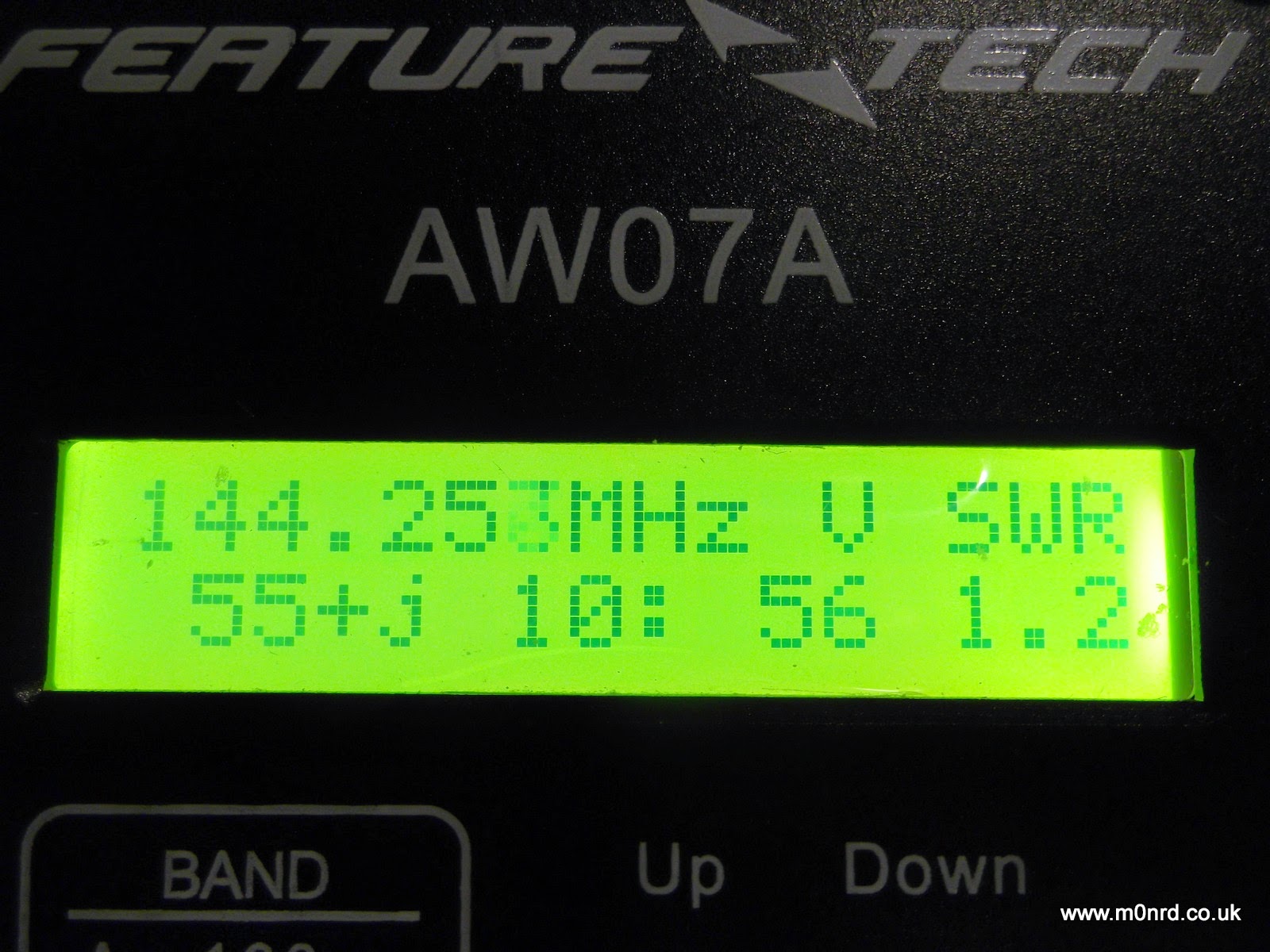
Feature Tech AW07A Antenna Analyser – First impressions
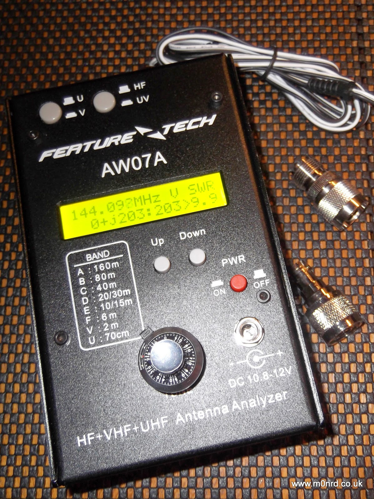
It is about the size of a thick paperback book and is a powder coated steel case similar in style to that used by MFJ equipment, indeed the MFJ-266 analyser appears to be a re-badged version albeit for a lot more money than this unit can be purchased.
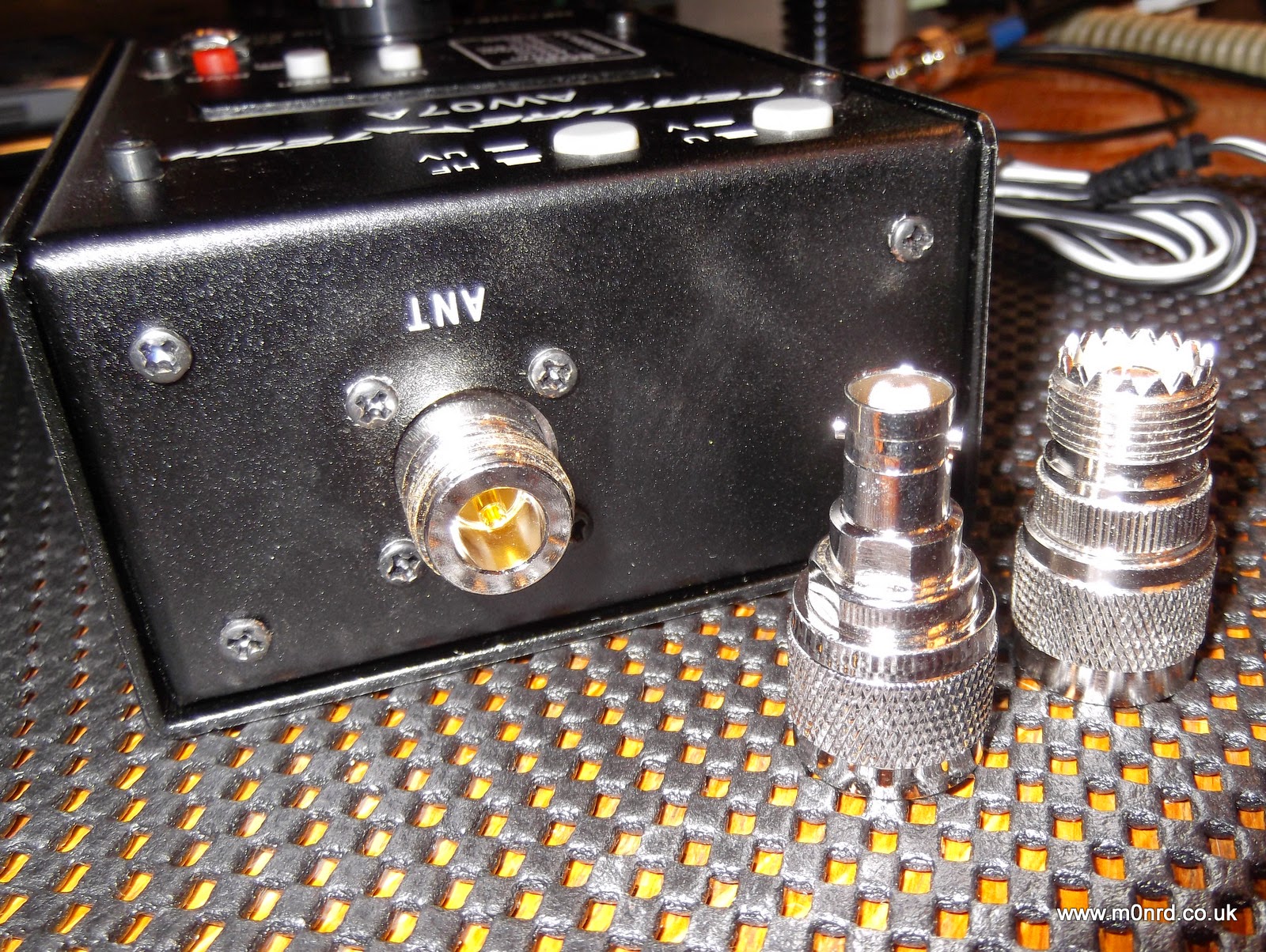
It can be powered by batteries fitted internally or by an external supply and is supplied with a power cable for connection to an external supply, mine was white/black rather than the normal red/black cable. It has a N-Type socket for the antenna and comes with two adapters for PL259 and BNC connectors.
It has a power button near the external power socket, two buttons on the top select HF and VHF/UHF operation and two other buttons marked UP and DOWN to select operating mode and/or the frequency band being used. Unfortunately one thing it doesn't come with is a manual but a copy can be downloaded from QSL.net or a slightly different version from the manufacturers website. But I actually downloaded the manual for the MFJ-226 has it is much more detailed.
The front panel decal and manual state it can be run from 10.8-12V, in fact the manual states it should ideally be less than 12.5V and no more than 13V. While doing some research I found the reason for this limitation hidden away on this aliexpress webpage "Avoid higher than 13V power supply circuit for the UV segment may be damaged due to excessive power dissipation." So this would seem to rule out using a standard 13.8V power supply.
It can be fitted internally with eight AA batteries and this is the way most people would use as it offers portability. Removing four screws allows access to the battery compartment and the internals electronics seem well built.
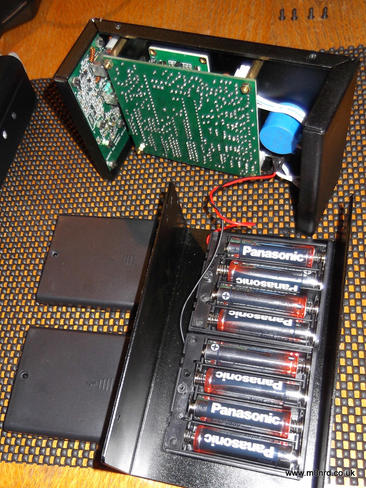
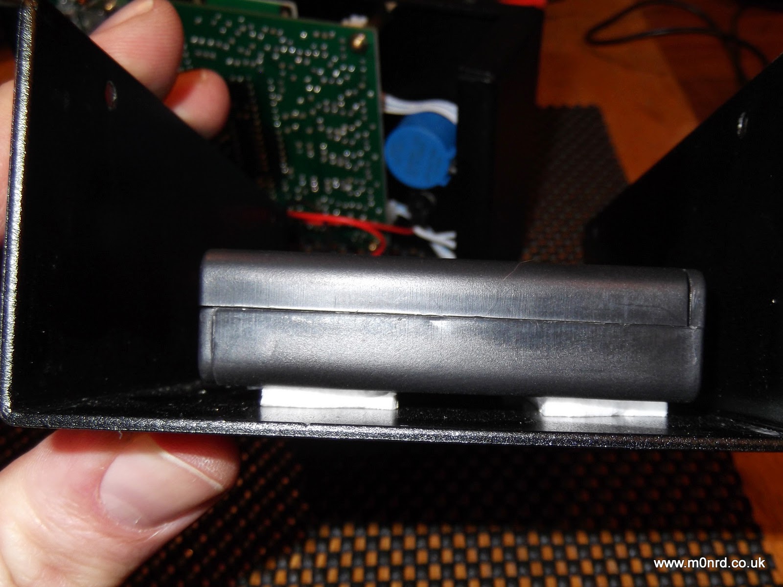
It takes eight AA batteries, in two boxes. The battery boxes have lids secured with a small screws and are fixed to the case using simple sticky pads, while secure at the moment I can imagine in time the adhesive could dry-out and become unstuck leaving the battery boxes loose inside the unit.
The display is a simple two line LCD with an optional bright back light which can be turned on during the power up sequence. The display shows the battery or supply voltage and pressing Down puts the unit into a frequency counter mode. Pressing Up puts into the antenna analyser mode.

In the analyser mode it is a simple case of selecting the HF, VHF or UHF mode. VHF works from 85-185MHz, UHF is 300-390MHz, the HF is split into six overlapping bands A: 1.5-2.7 MHz B: 2.5-4.8 MHz C: 4.6-9.6 MHz D: 8.5-18.7 MHz E: 17.3-39 MHz F: 33.7-71 MHz selected using the Up/Down buttons.
Turning the vernier tuning knob adjusts the generated frequency the antenna is being tested against. I connected the analyser to my 2m YAGI antenna and turned the knob to find the lowest SWR

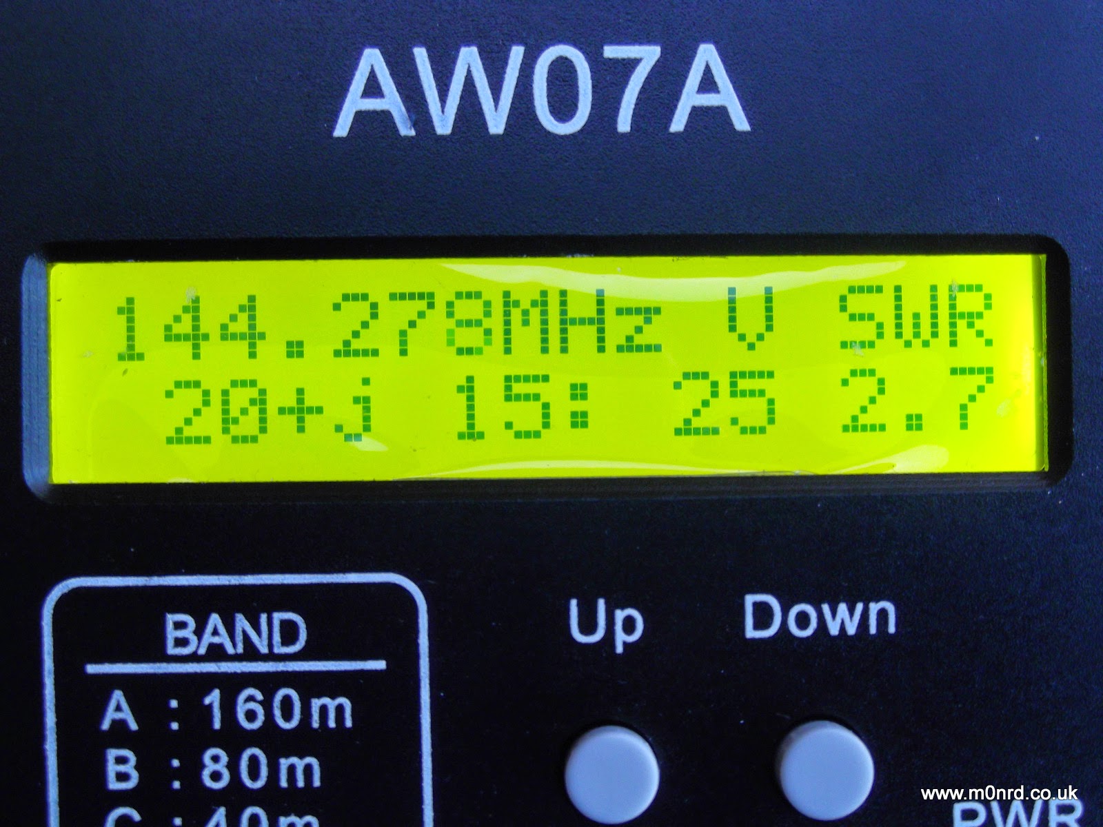
The manual describes what is being displayed (on UHF just the SWR is shown)
“139.763 MHz” is the frequency
“V “is the band (A,B,C,D,E,F in HF, V in VHF and U in UHF)
The bottom row shows the complex impedance Z = R + jX, so on this screen
“41” represents R = 41 ohms the resistive component
“18:” represents the reactance component value, jX = 18 ohms
“45” is the overall complex impedance magnitude Z = 45 ohms
“1.5” is the SWR value
As you can see for a 2m antenna something isn't quite right! The antennas were down due to last weeks strong winds so I was taking the opportunity to do some maintenance and tweaking of the 2m antenna since I'd seen an increase in the SWR during recent UKAC contests. I had suspected feeder issues, possible water ingress but I tried a dummy load at the antenna end but that read as expected (Z=50ohms) and metering the continuity of the feeder showed no issues, it just seemed to be resonant at too low a frequency.
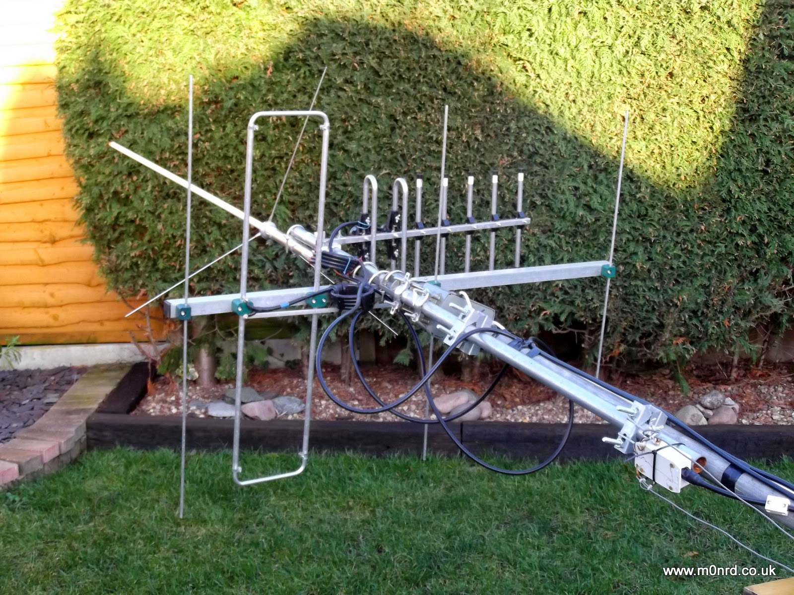
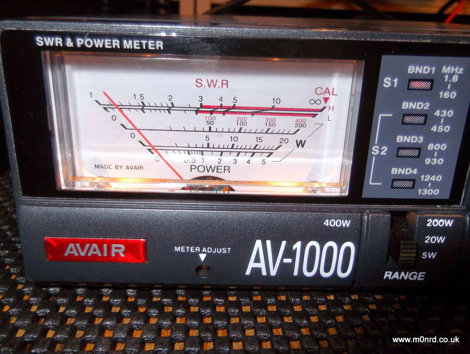
The analyser confirmed what I'd observed with a normal SWR/Power meter a higher than desired SWR in the middle of the SSB section of the 2m band.
Unfortunately I was unable to get it any lower than 2.5 and most adjustments seemed to increase the SWR. For peace of mind I double checked the analyser by swapping the feeder on to the 2m/70cm collinear and that was spot on
again I double checked the SWR readings back in the shack using the normal meter
While I try to sort out the antenna issue I can say the analyser seems to do its job well. The tuning knob is a little twitchy and has a bit of play which makes setting the frequency accurately a little harder than it should be but hopefully that might improve with use.
The unit also has other functions none of which I have used yet but it is bonus to have some useful test functions available in the shack.
The AW07A can be used as an inductance/capacitance meter by powering it up with the U or D button held down. The inductance or capacitance of a component fitted across the antenna socket is then displayed and this can be done for any test frequency by selecting the band and turning the tuning knob.
As I mentioned earlier the unit can also function as a frequency counter that can measure signals between 1 and 500 MHz and can be used to give an indication of relative RF field strength. A signal source or an external antenna that yields a usable signal level may be connected to the analyser’s antenna jack. The usable signal range is quoted as -20dBm (30mV) to +10dBm (1V). Note that the display reading is a RMS value.
Obviously in the antenna analyser mode the output which is approximately 2V in magnitude can be used as a signal source, with 20dB of second harmonic suppression.
The MFJ manual goes into some detail of how this all works and how to use the analyser for a number of common tasks such as checking baluns, making 1/4wave stubs or measuring velocity factor of coax.
While the AW07A has some obvious shortcomings and may not be a precision device I am impressed with it and what it can seemingly do. It is shame about the lack of a manual but I am not sure getting one is justification for the premium price of the near identical MFJ unit.


