Posts Tagged ‘amateurradio.com’
 Hellschreiber and microprocessors – Bridging more than 80 years
 January 17th, 2012 |
  Author:
 ZL1HIT (Bryan Rentoul) has bridged a gap of more than 80 years by combining the text transmission system developed by Rudolf Hell in the late 1920’s with current microprocessor technology.
 |
| A sample of received Hellschreiber test from Bryan’s beacon |
Hellschreiber sends a line of text as a series of vertical columns. Each column is broken down vertically into a series of pixels, normally using a 7 by 7 pixel grid to represent characters. The data for a line is then sent as a series of on-off signals to the receiver, using a variety of formats depending on the medium, but normally at a rate of 112.5 baud.
This process was historically accomplished with mechanical equipment but there are very few examples of this equipment still in operation and it is now sent and received by computer. Hellschreiber is very tolerant of noise and interference and requires only simple transmitters and receivers to work effectively.
 |
| German Hellschreiber unit in operation |
With a microprocessor generating the digital on-off signals a simple crystal oscillator transmitter can be used to form a beacon station, one that transmits a call sign and perhaps some other information over and over. Changing the transmitted message is as simple as reprogramming the microprocessor or having it respond to a connected input, for Eg. A thermometer, light sensor, switch, etc.
Receiving the signal and decoding requires a radio receiver capable of CW reception and a computer running any of several free software packages like FLdigi or Digital Master 780.
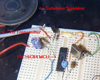 |
| The ZL1HIT beacon using a PIC microprocessor and a simple crystal oscillator transmitter. |
For more information and the PIC microprocessor source code please visit the web page of Bryan Rentoul here : ZL1HIT Hellschreiber / PIC Beacon
Anniversary of Vail’s First Demonstration of the Telegraph
Over at “This Day in History,” the lead story today is “Morse demonstrates telegraph.” It leads off, “On this day in 1838, Samuel Morse’s telegraph system is demonstrated for the first time at the Speedwell Iron Works in Morristown, New Jersey.” Well, I thought, surely this is worthy of a blog post, so I poked around on the web to learn more.
 It turns out that this first demonstration was put on by Morse’s partner, Alfred Vail. Vail had first become involved three months earlier when visiting his alma mater, the University of the City of New York. He stumbled upon Samuel Morse demonstrating his “electro-magnetic telegraph” with over one-third of a mile of wire coiled around a room. Vail was hooked. He convinced his brother George and father Stephen to support further development of the telegraph at the Speedwell Iron Works, and he signed an agreement with Morse to turn Morse’s crude prototype into a market-ready model — at his own expense — by January 1, 1838, in return for a minor share.
The challenge was to get the thing to work with a length of wire much longer than Morse had managed to use. Alfred Vail recruited an apprentice at Speedwell, William Baxter, and got to work. After many frustrations, they finally succeeded in getting their model to work:
At last on January 6, 1838, the machine was ready to be demonstrated. The cotton-covered hat wire was coiled around the room on nails to equal a distance of two miles. Alfred sent Baxter to “invite Father to come down and see the ‘Telegraph’ machine work,” which sent the eager lad plunging into the cold afternoon without stopping to throw a coat over his shop clothes.
The machine that sent Stephen’s message, “A patient waiter is no loser,” was still far from perfect. A few days later [January 11] several hundred men and women crowded into Speedwell to witness the first public demonstration. The message this time had a practical cast: “Railroad cars just arrived, 345 passengers.”
I’m not sure how these messages were formatted, but most likely they were not sent letter-by-letter. In those early days messages were laboriously sent using numbers that were assigned to commonly-used words. Eventually the “Morse Code” alphabet would replace this system, though great debate rages over who invented it.
Vail himself gives credit to Morse for the alphabetical system on p. 30 of his book, The American electro magnetic telegraph: with the reports of Congress, and a description of all telegraphs known, employing electricity or galvanism (available online for free), though some doubt the truth of this statement. Many years after his death, someone even sneaked in and engraved on Vail’s tombstone, “INVENTOR OF THE TELEGRAPHIC DOT AND DASH ALPHABET.”
Whoever invented the alphabet, what does seem clear is that Vail was the one who invented the straight key, an elegant improvement upon the cumbersome machines first used to encode messages. Today, you can even purchase a replica of Vail’s “spring key” from Kent Morse Keys!
Alfred Vail became increasingly frustrated by Samuel Morse’s lack of involvement in the development of the telegraph while publicly taking all the credit. Vail stuck with it for ten years before finally leaving the telegraph behind.


Minimum-Loss Matching Pad
In my last post I promised to write about the minimum-loss matching pad that I’m using to couple my signal generator to the device I’m testing. The source impedance of the generator is 600 ohms and the output is intended to be terminated in a 600 ohm load, but the device I’m testing is only 228 ohms. The way to match this with the lowest loss is with a transformer, but it is inconvenient and unnecessary to come up with a transformer for every mismatch this piece of test-equipment will face.
Thanks to advice from the ham who is guiding me in this project, I’m using a minimum-loss matching pad, also known as an “L-pad,” to match these two impedances. (I’d tell you who this fine fellow is, but to keep you in suspense about my project I’ll wait until my final write-up. If I name him now, the cat will be out of the bag!) This quick, cheap, and easy match requires only two resistors:

Courtesy of http://www.microwaves101.com/encyclopedia/attenuatorL-pad.cfm#minloss
To calculate the value of the resistors and to calculate the loss of the matching pad, use these formulas (A spreadsheet that uses these formulas is available through this webpage.):

In my case R1=472, R2=290, and the loss is -9.25 dB. That loss is pretty significant, but it is acceptable for this application. Remember this is a minimum-loss matching pad, not a no-loss matching pad. Using what resistors I had on hand to come as close as I could to the required values, I soldered this pad on a generic PC board from Radio Shack that I cut in half using my Dremel tool with a cutting wheel:


For more on this topic, I commend to you this webpage on “Impedance and Impedance Matching.”


1Hz-2MHz Function Generator Kit
 After building the “Accurate LC Meter Kit” from Electronics-DIY.com, I turned to their “1Hz – 2MHz XR2206 Function Generator Kit”. All parts necessary to complete the kit were included, though not exactly as pictured on their webpage — two of the WIMA capacitors had been replaced with substitutes and there was no IC socket. All components were through-hole; soldering the kit together went quickly and easily.
If you build one of these kits you’ll need to provide your own power source as well as your own pin-connectors (if you choose to use the pins provided). As with the LC Meter, I used a size M coaxial DC power jack to accept a plug from one of the wall-wart power supplies I have around here. I didn’t bother to install a power switch in either unit since I won’t be using them very often; I won’t leave them plugged in between uses.
The fellow at the local Radio Shack gave me some pin-connectors for free, clipping them off of some battery packs that were in a box for recycling, though he only had two-pin connectors. Since one of the pin-sets has three pins, I just soldered a piece of hookup-wire to the third pin. If I had to do it all over again, I wouldn’t bother with these pins — I’d just solder hookup wire right to the PCB. By the way, if you ever try soldering to a pin make sure you clip a heat-sink to the pin before heating it up. The plastic base of those pins melts pretty quickly!
I chose a plastic project box from Radio Shack to house this function generator. Using a Dremel tool with an engraving cutter (at the lowest speed — 5,000 RPM), I put three notches in one side of the box for the potentiometers, a notch on one end for the two switches, and ground down all four stanchions on the floor of the box since otherwise the potentiometers would have extended too high to allow the lid to fit. That Dremel tool sure is handy! A few knobs from Radio Shack finished off the project.
The two outboard switches allow you to select between three waveforms — sine, triangle, and square. I don’t have an oscilloscope so I can’t tell you how the waveforms look, but I can at least tell you that the sine wave sounded pure when I hooked my headphones up to the output with a matching pad. I am pleased to report that the signal generated by this function generator is very stable. Four DIP switches on the PCB allow you to select between four frequency-ranges, and two potentiometers allow you to tune within the selected range. One of these two potentiometers provides coarse tuning, and the other provides fine tuning. The third potentiometer controls the amplitude of the signal generated (note: amplitude decreases as you turn this potentiometer clockwise).
If you build this kit you’ll want to hook it up to a frequency counter. Two pads on the PCB are provided for this purpose. I have a piece of coax hanging out of the back of the box for connection to my own frequency counter — not that you have to use coax, but it was handy for terminating with a BNC connector. (If I were really classy I would have put this coax through its own hole in the project box, but hey, this is a piece of test equipment — I just ran it through the big hole I made for the RCA connector.) When I hooked up my frequency counter I noticed that the published ranges for each DIP switch were just rough approximations, but I was pleased to see that this frequency generator covered the entire published range and more — up to about 2.4 MHz, if I recall correctly.
Here is a slideshow of photographs I took of the completed function generator:
The source impedance of the generator is 600 ohms and the output is intended to be terminated in a 600-ohm load. In my next post, I hope to discuss the construction of a minimum-loss matching pad to hook it up to a piece of equipment that has a different input impedance.


Accurate LC Meter Kit
Update (3/7/12): Yesterday I prompted [email protected] for a reply, mentioning the number of pageviews this post has received. I received a prompt and polite response. I learned that I was mistaken in expecting the meter to read capacitors 1 uF or higher, since the published range of the meter is only 0.1pF-900nF. There was no explanation of why I am having problems with inductors that are within the published range of the meter. However, I was quite favorably impressed by an offer to test and fix the kit at no extra charge! I shall take them up on this offer and keep you updated.
Update (2/8/12): I am having trouble with this LC Meter. It gives me the same reading for all capacitors 1 uF or higher, and the same reading for all inductors higher than about 70 mH (this last value is just a guess): 838.8 nF and 83.88 mH, respectively. As you can see the digits are the same. It seems to work for really small capacitors and inductors, but anything bigger and these are the only readings I get. I emailed [email protected] on 1/8/12 about this, but as of 2/8/12 I have received no reply. Unless and until I learn the problem is due to some error of my own in constructing this kit, I recommend against purchasing it.
 Yesterday evening I finished building the “Special Edition Accurate LC Meter Kit with Blue Backlight LCD”, available from Electronics-DIY.com for $69.95. I have no experience with such devices; a more experienced fellow told me he was impressed by its specifications, so I ordered the kit. Soldering it up was a snap. The main printed circuit-board is all through-hole construction, and the LCD-board that mounts over the top of it requires nothing but a connector.
If you want to build one of these you may want to order this version of the kit instead of the one I purchased: Accurate LC Meter Kit with Green Backlight LCD, for $59.95. My kit’s “Blue Backlight LCD” turned out to be green anyway, and I think the two kits have the same circuit, save an adjustable potentiometer on mine that controls the contrast of the LCD (which I just set to maximum anyway). Certainly the cheap case that comes with the kit I ordered is not worth the extra $10 — to use it you have to carve out a bunch of stuff (to make room for the circuit-boards), including two of the four stanchions that attach to the lid. After going to all that trouble (I used a Dremel tool) you are left with a case that requires adhesive tape to hold down one side of the lid!
The instructions that came with the kit were pretty sketchy, mostly limited to how you need to carve up the case (by the way, the measurements were wrong, so ignore them). The only thing that got me into trouble was the voltage regulator, which gets in the way of the LCD-board (and protrudes too high to seat the lid of the supplied case) if you solder it in the way you normally would (which I did!). By bending the voltage regulator out at angle I managed to get the LCD-board mounted, but the lid still won’t seat properly. Learn from my mistake, and bend the leads of the voltage regulator into a Z so that they lay flat on the board and allow the voltage regulator to sit just off the edge of the board. (Of course, this only matters if you try to use the case provided.)
You’ll need to supply your own power to this unit. There isn’t enough room in the case for a 9V battery, so I purchased a DC socket. You’ll also need to supply your own connectors for testing inductors and capacitors; the photograph on the Electronics-DIY.com website shows them in the case, but they aren’t supplied. I used banana-plug sockets. You’ll also need to supply your own pin-connectors if you use the supplied pins on the circuit-board, and you’ll need your own stand-offs if you want to support the LCD-board (only two of the four screw-holes match up with the lower PCB, but that’s probably good enough).
There is no way to select the units displayed on the screen, e.g. pF vs. nF. But the dearth of selector switches is actually one of the nice things about this unit. There is no need to select a range of capacitances or inductances. The only thing you have to do is plug it in, hit the reset button whenever you want to calibrate it, and stick in a capacitor to get a reading. If you want to test an inductor, you simply press one button to select inductance-mode, then attach your inductor. It just works — and it works with precision.
Here is a slideshow of some snapshots that I took with my cell-phone. They didn’t turn out very well, but they’re good enough to give you an idea of what it looks like. Notice that I used black electrical tape to mask the edges around the LCD. That’s because the opening I made was downright ugly. Next time I’ll try using a cutting wheel on my Dremel tool instead of a grinding tip!


ARES in a Small Town
I’m afraid I haven’t spend much time on the air lately, because what time I have for ham radio has been devoted to a project that began as an idea for a blog post and has grown . . . and grown . . . and grown! I hope to write it all up when everything comes together, but I don’t want to give it away just yet. For now I’ll just give you a few clues: I’ve been assembling some test equipment, including an inductance-capacitance meter kit and a signal generator kit, and I received a tantalizing shipment in the mail today from a fellow who wrote a stellar article in QST 31 years ago. Stay tuned!
 On another front, I finally got to meet a local ham who is the IT manager at the hospital in our small town (population ~3K) — Mr. Andrew Rosenau, KCØYFY. I’ve been meaning to introduce myself to him ever since moving out here, but when I found out a few days ago that he is our county’s ARES (Amateur Radio Emergency Services) Emergency Coordinator, I sent him an email right away. He replied immediately, and today, after wrapping up a meeting in another part of the hospital, I ambled over and chatted with him for a few minutes in his office.
Behind him on his desk sat an HF rig, a 2M rig, and a TNC. Andy explained that he was a ham before moving here, and he got involved with ARES when the hospital became interested in EmComm. But with so few hams in our area (only 14 in the whole county), there hasn’t been much in the way of ARES activity. I volunteered to do what I could, and he said that for starters I could act as a back-up operator there at his station if he were unavailable in time of need.
It turns out that Minnesota has a huge packet network, and a radio club in a nearby town has even installed an antenna right in our city to extend this network. That was news to me! I’m going to have to dig up my old TNC and see if I can get it running. As much as I prefer CW, I have to admit that it does seem like an excellent way to handle traffic in an emergency.
ARES has always interested me. I’ve never been involved in it before, back when I lived in the Twin Cities, but now I think I owe it to my community. It appears that while there is less opportunity to do much ARES work out here in the sticks, there is also more opportunity for one ham to make a difference. So far Andy has been all alone in his effort — if even one ham chips in, that would double the number of ARES operators in our county.
Andy’s wife is a ham, too! I hope to have them over for dinner one of these days and get to know them better.


Summits On the Air Taking Off in Colorado
 The Summits On The Air (SOTA) program was launched in Europe in 2002 but is just now making its way to the United States. Recently, there has been a surge of activity in Colorado as the program gains traction here.
The basic concept of SOTA is an award program that rewards the radio operators that activate summits and the radio operators that chase summits. For those of us that enjoy the mountains and enjoy ham radio, this is a great fit. I won’t go into all of the rules here (Warning: There Are Lots of Them), so check out the SOTA web site for the complete details.
Steve WG0AT (World Famous Alpha Goat) just published another one of his Rooster and Peanut videos that capture his recent activation of Mount Herman. I managed to work Steve on 2 Meters and I make a cameo appearance in his video below as I make my first official SOTA contact.
Steve has been activating SOTA summits for a while now and others are joining in. Here’s a video from Pikes Peak with Mike, KD9KC and Ron,WT5RZ on North American Summits On the Air weekend.
Recently, Jerry KD0BIK succumbed to the SOTA addiction, activating Mount Herman and Green Mountain (click on the mountain names to see his blog postings). Chris NW5W has also been active…check out his web site here.
There are numerous SOTA videos on youtube from all over the world.
The SOTAWatch web site is dedicated to posting future SOTA operating plans (Alerts) and SOTA activations in progress (Spots). The North American SOTA Yahoo! Group is another great source of information.
See you on a summit soon.
73, Bob K0NR