Posts Tagged ‘amateur-radio cw’
 This is not the wattage you’re looking for… move along
Getting hot under the collector/base junction
Where did my power go?
My Elecraft W1 power meter has been absent from the antenna chain for a while due to a jumper cable shortage when I last reconfigured my shack. But now the W1 meter is back in the chain and it revealed something a bit worrisome about the 1Watter transceiver...
My Elecraft W1 power meter has been absent from the antenna chain for a while due to a jumper cable shortage when I last reconfigured my shack. But now the W1 meter is back in the chain and it revealed something a bit worrisome about the 1Watter transceiver...
I've had a bunch of QSOs using the 1Watter both in the shack and in the great outdoors. The 1Watter is my first home built transceiver (albeit from a kit) and has been a great learning experience. It is called a 1Watter (or 1H2O as Diz calls it) because it nominally produces an output of 1 watt.
The Elecraft W1 power meter is a nice, inexpensive QRPp to QRO meter because it measures from 150 watts all the way down to 150mw.
The little 1Watter transceiver does indeed produce just a hair over 1 watt when it's first powered up. Tonight I tossed my call out on 7030 kHz and was promptly answered by N4DR up in Maryland. He was running a YOUKITS TJ5A at 5w. When we started the QSO my W1 meter showed that my 1Watter was outputting between 900mw and 1w to my mighty attic antenna.
Then by the second exchange in the QSO I noticed my output power dropping down to 700mw. By the end of our ragchew my 1Watter output had dropped to 500mw.
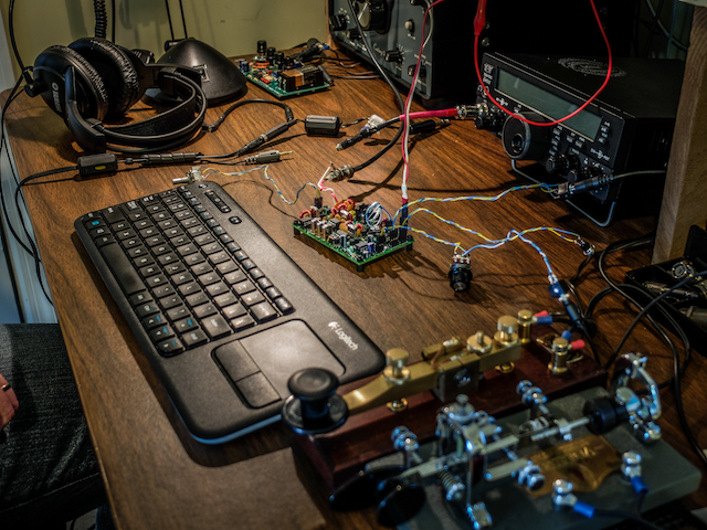
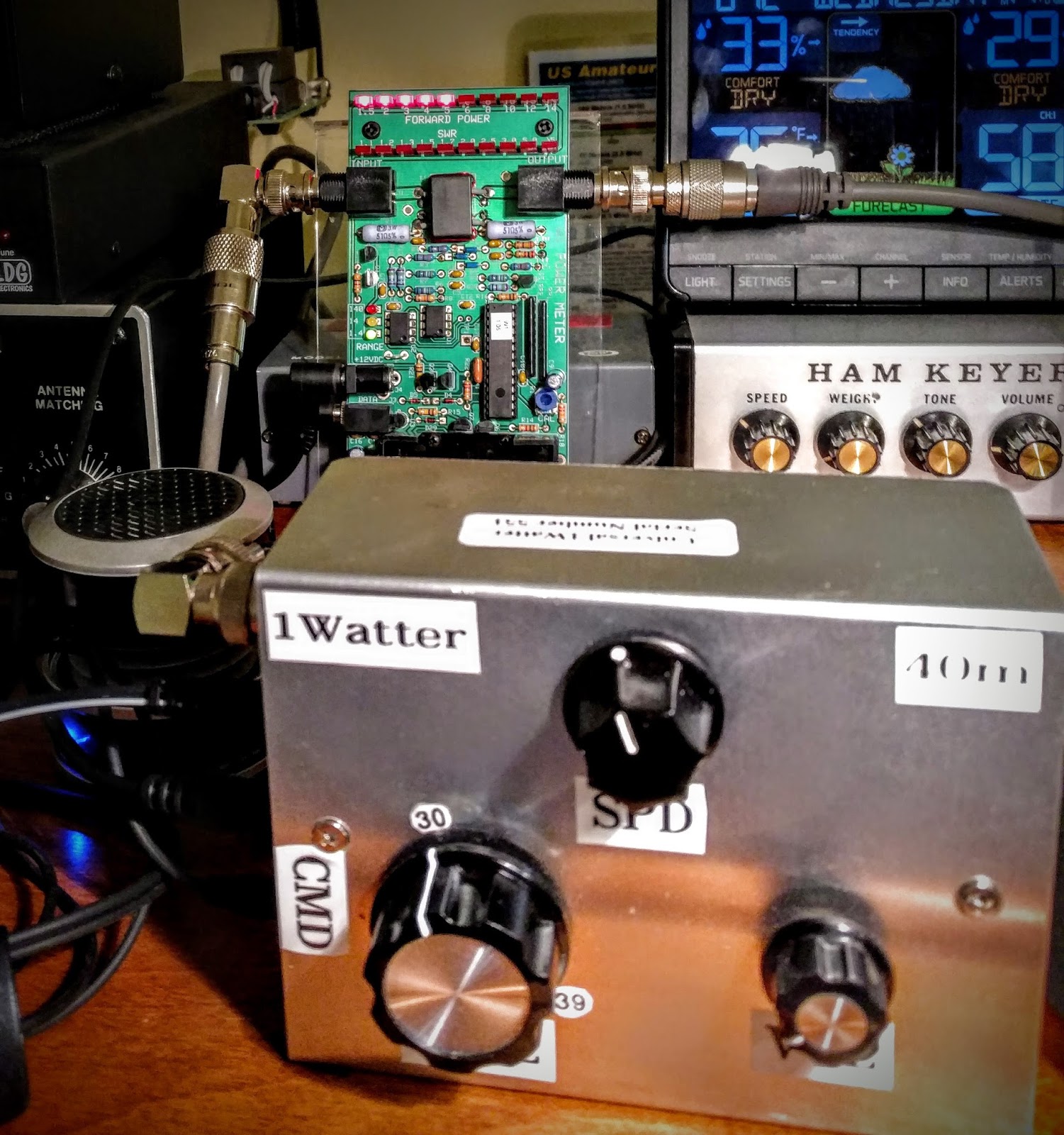 |
| Power meter in background showing 500mw by the end of the first QSO |
As I ended that first QSO I was called by another station (AF4YF) who was running a 2 watt homebrew xcvr. And by the end of that QSO the 1Watter was producing less than 300mw. I felt that some investigation was in order.
Heat is the enemy
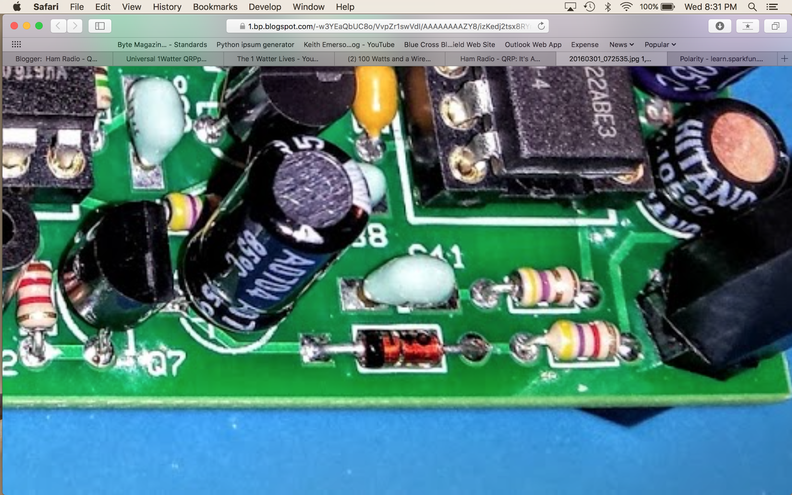
The 1Watter uses a 2N5109 NPN RF transistor for a final. Transistors really are not fans of heat.
The maximum power output available from a power transistor is closely linked to temperature, and above 25°C falls in a linear manner to zero power output as the maximum permissible temperature is reached.
My 1Watter kit included a friction fit heat sink, seen at the top of the photo below. But apparently this heat sink either saturates quickly or doesn't have sufficient surface to conduct away the heat. My enclosure is not vented but it is alumunium and I don't feel any appreciable temperature rise above ambient so I don't think venting is in order yet.

I allowed the 1Watter to rest for 30 minutes following the QSOs, still powered but not transmitting. That only resulted in the output power getting back into the 700mw range. I'm considering increasing the bias to start with a higher transmit power so that it will maintain 100mw but I'm afraid of destroying the transistor. I might also try some conductive paste but it's messy and I'm not sure it will help if it can't be pressed between two surfaces.
I'd appreciate any constructive suggestions. I'm still a noob at this electronics stuff.
But the real moral of the story is...
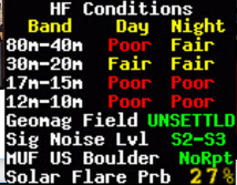 |
| Band conditions on the evening of this QSO |
So as I sat here wondering why my 1 watt radio was only producing a 1/2 watt now, I reminded myself that I was having extended QSOs using a (now) 500mw radio with other QRP operators (5w and 2w). I was also using my attic antenna, not some multi-element beam on a tower. Band conditions on 40m were also a limiting factor tonight (see snapshot at right).
These were not simply swap 599 TU QSOs, we were exchanging information on multiple go-rounds with solid copy.
So if you're reading this blog you likely have some interest in QRP. Hopefully this is just yet another reminder that we often don't need as much power as we think we do for communications. I was getting discouraged this summer due to the decreasing sunspot cycle and thinking "I'm gonna need to operate QRO more and likely get a real antenna put up in my yard".
But it's times like this with my 1Watter that keeps reminding me to lower my power and raise my expectations.
But it's times like this with my 1Watter that keeps reminding me to lower my power and raise my expectations.
So lower your power and raise your expectations...
72 / 73
Richard, AA4OO
Bugging Out
Vibroplex Bug QSO
Sometimes I'm in a mood to use my bug. I'm still a relatively new CW operator and using my Vibroplex Original Bug is both novel to me and a challenge compared to my Kent Straight Key or using paddles.
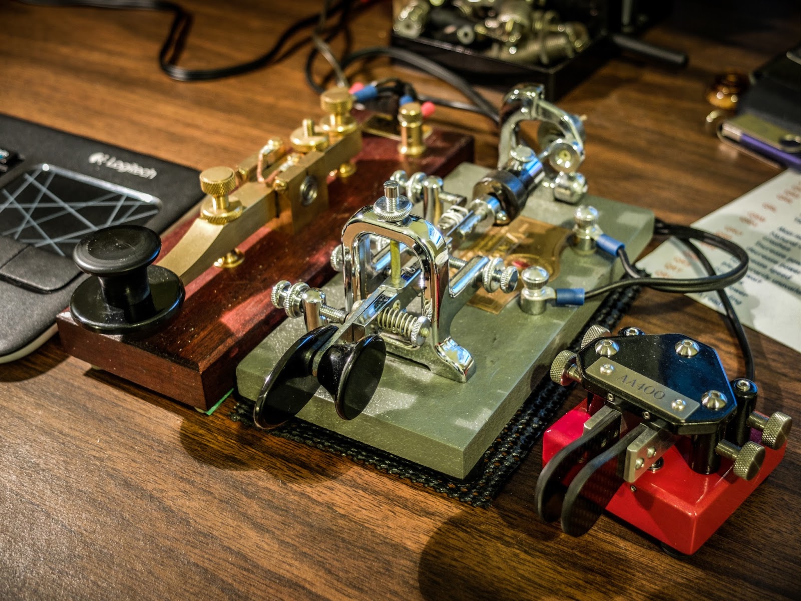 |
| The key lineup with the Bug in the center |
I purchased my bug used on a well known auction site for about $65. It dates to sometime in the mid 1970s but it doesn't differ much from bugs made in the past 75 years. I have added some weight to slow it down to around 19 wpm DITs by taping a heavy spacer onto the factory pendulum weight as well as adding a heavy metal spacer to the end of the pendulum. The weight on the end of the pendulum is held on by a simple plastic drywall screw anchor. I can pull the weight off the back quickly if I want to let it go up to about 25wpm DITs. Without the extra weights this bug sends at around 27wpm at it's slowest speed and up to... well I don't know how fast because I can't control it at the fastest speed yet and I certainly can't copy others at that speed so I usually keep it below 20wpm for now.
If you haven't used a bug I encourage you to give it a try. It's a challenging key to get the hang of but the effort to learn it is fun and rewarding. I especially enjoy the tactile feedback from that swinging pendulum and the the click-clacking of the pendulum against the hanging damper.
I was using my Ten-Tec Eagle (model 599) purchased used from a local ham. The Eagle is a super little QRO radio although in this QSO my output is 5w. If you have sharp eyes you may see that the power level is set to 7w but that is actually 5w output according to my external meter. The 100 number under the CW symbol is the bandwidth that I was using. I generally keep the bandwidth at 500 Hz but there was a station operating above us that I wanted to mask.
 |
| Ten-Tec Eagle 599 |
The Eagle is a great CW rig. This model has 3 front end crystal filters 2400Hz, 600Hz and 300Hz giving it nice selectivity for any mode.
I was working Ed, KG4W in VA who is an SKCC member. If you want to work other manual key stations 3550 kHz is a calling frequency for the SKCC. Ed told me during the QSO he was using a VIZ vertical bug which is a unique and interesting bug design.
He reported my signal as 599 and he was 599 as well. I was running 5w output power to my 80m OCF Dipole. He was using an Yaesu at 100w to a fan dipole. 5w was sufficient for this QSO but if he had reported me as 559 or weaker I would have raised my power to 20w to make copy for him easier. I enjoy using QRP but when I rag chew I don't want to make it difficult for QRO stations to copy me if I can help it so having the Eagle allows me to raise my power if necessary for the communication.
The QSO
So here's the qso between two bug operators. I hope you enjoy it...
That's all for now
So lower your power and raise your expectations
72/73
Richard, AA4OO
Get your news the old fashioned way
Morse News
I'm always looking for ways to improve my CW copy skills. When I'm away from the radio and have some spare time I use a program called Morse News.
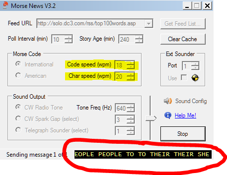 |
| Morse News interface displaying a "Top 100 words" feed scrolling at the bottom |
It's an application that pulls RSS feeds and translates them to Morse. It has useful configuration options and even allows different "sounders" to be used.
For instance: you can listen to Morse the way railroad and Civil War telegraphers heard it via the clacking Telegraph sounder, or the early 20th century spark gap transmitters.
For instance: you can listen to Morse the way railroad and Civil War telegraphers heard it via the clacking Telegraph sounder, or the early 20th century spark gap transmitters.
The application is free but only runs on Windows computers. I'd love to see something like this for my phone.
Here's the link: http://sourceforge.net/projects/morse-rss-news/files/Morse%20Code%20Tools%203.2/MorseTools32Setup.exe/download
As with all software downloads from an untrusted source use your own best judgement whether to install this software and protect yourself from malware. I haven't detected any malware from my install but that doesn't mean it's not there.
Here's the link: http://sourceforge.net/projects/morse-rss-news/files/Morse%20Code%20Tools%203.2/MorseTools32Setup.exe/download
That's all for now
So lower your power and raise your expectations
72/73
Richard, AA4OO
It’s ALIVE !
The 1Watter 40m #551 -- Lives
 |
| The 1Watter 40m on it's inaugural QSO |
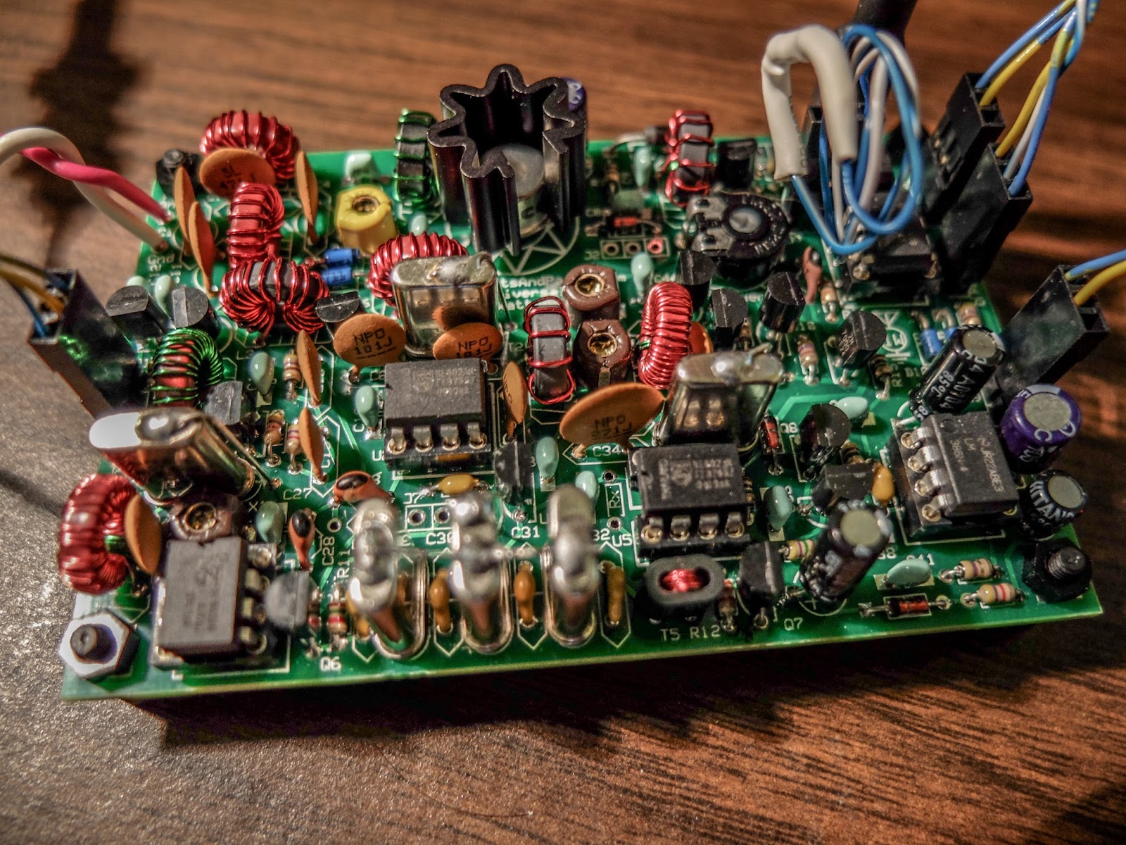
 |
| Inside the enclosure |
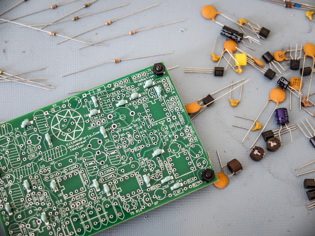
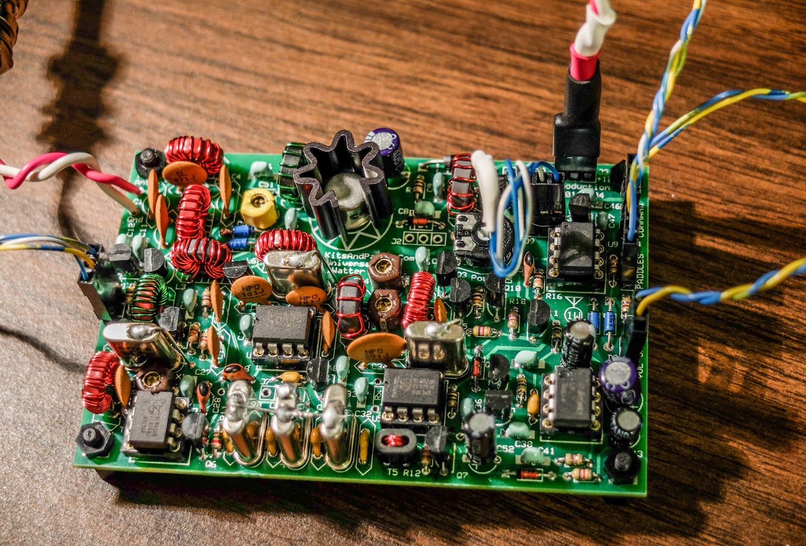
The 1Watter is a kit from kits and parts dot com
The Universal 1Watter (also called the 1H2O) is a full featured little superhet radio transceiver that you can build for about $50. It doesn't come with an enclosure, a tuning pot, speed pot or an on/off switch so that will cost extra unless you already have some in the junk bin.
Some of the features include;
- 1 mighty watt of output
- Good selectivity from the 3 crystal filters
- A VCXO tuned frequency range for the 40m band from approximately 7,020 kHz through 7,039 kHz
- A built-in full functioned keyer with provision for adding a speed pot and messages
- Included command button accesses the functions of the electronic keyer
- Natural sounding sidetone (nicer than my Ten-Tec Century/21)
The Build
The kit is delivered in a box and inside are a couple of brown paper bags stapled together. Inside one of the bags are a couple of plastic bags with the components. The other bag contained the header kit. The ferrite toroid mix types are separated in different unmarked plastic bags so don't mix them up (the instructions tell you which bag has each mix). If anything is missing the kit supplier (Diz, W8DIZ) is very responsive.
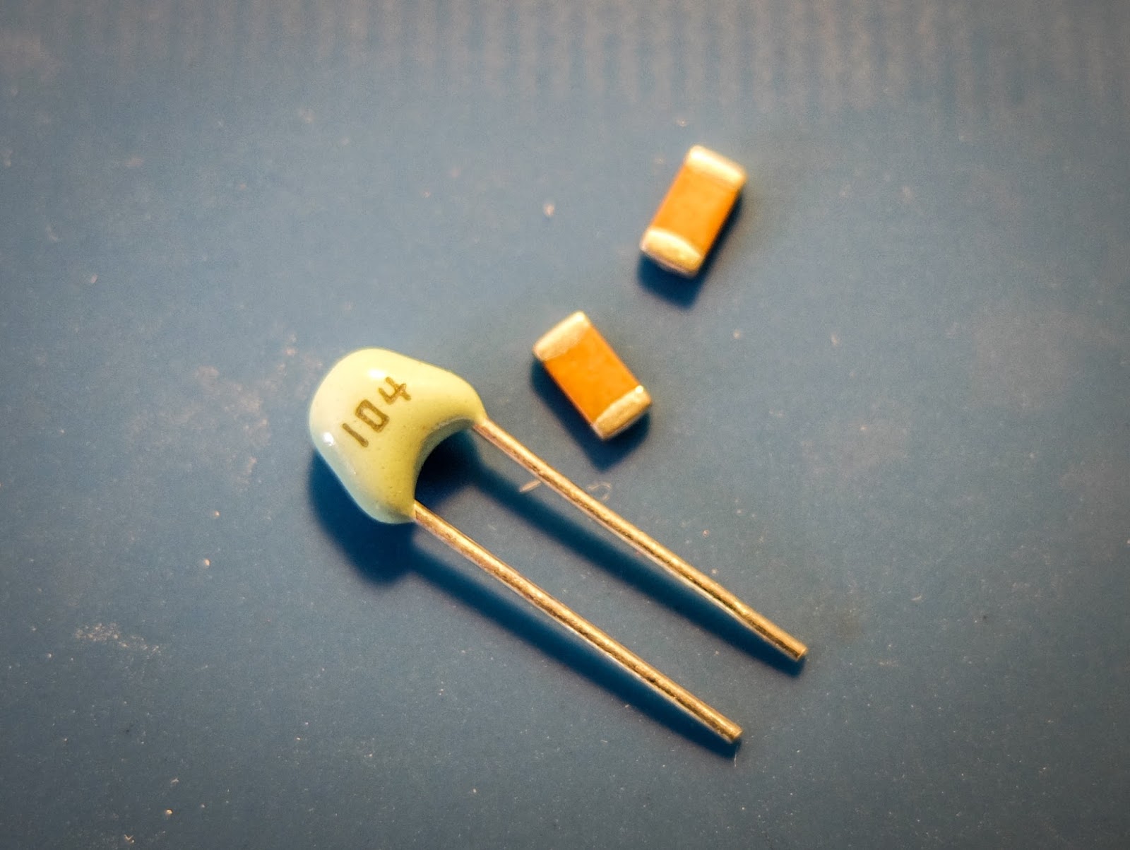
The kit includes both SMT caps and through hole caps. I tried to solder one of the SMTs but I didn't have the right kind of tweezers to hold it in position for soldering so I used the through hole caps.
 |
| SMT and through hole caps are supplied |
This is the 3rd revision of the Universal 1Watter board and I was the first to build the 40m version.
While the schematic was correct, some of the instructions weren't sorted out properly for the 40m kit. I related issues as I found them to the designer and he promptly updated the online documentation.
I soldered the components and wound toroids as I had time over a few evenings and the initial voltage tests went well.
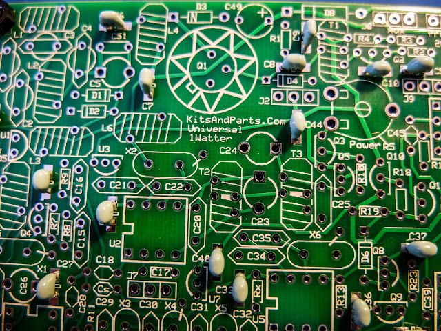 |
| using through hole capacitors rather than the SMTs |
 |
| some of the bits and bobs |
 |
| build is progressing |
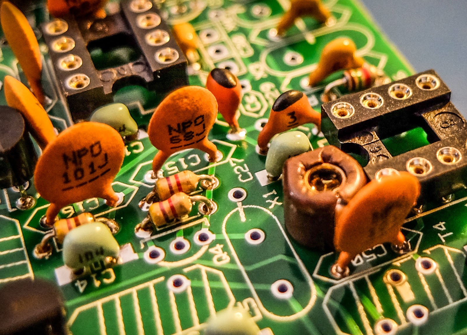 |
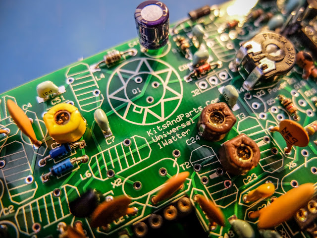
| close up |
 |
| XTAL filters give it good selectivity |
 |
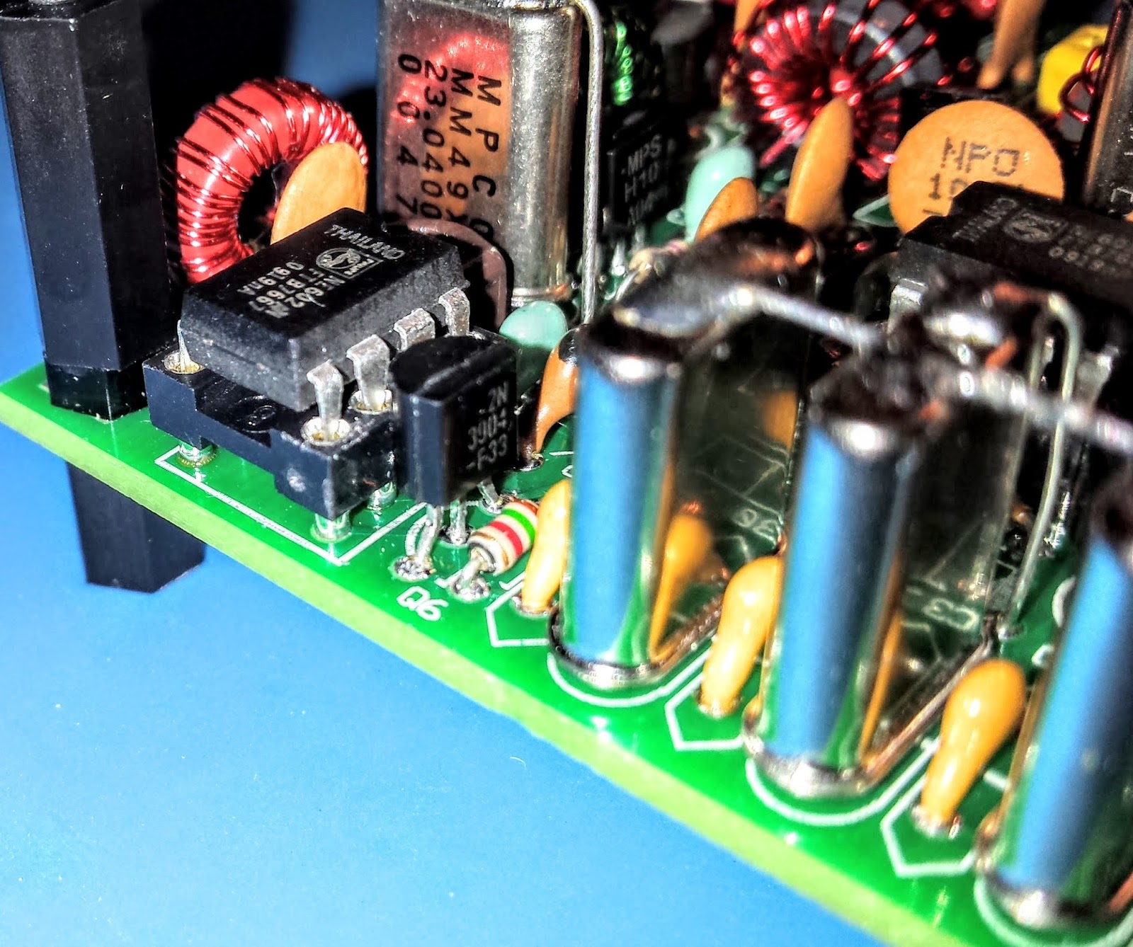
| Everything except the final transistor |
 |
| AGC circuit |
Debugging
When the build was completed I connected the rig to an antenna and heard nothing.
The keying circuit and transmitter worked fine and I verified those functions but the receiver was deaf as a stump.
Thus began a number of days of investigation. Diz (the creator of the board) guided me through a number of debugging steps.
The first recommendation was to examine and rewind the binocular toroid balun that transformed the impedance from the xtal filters to the input of the U5 oscillator. He believed that I may had wound it incorrectly. I desoldered it and rewound it but that did not resolve the issue.
He then guided me through determining if one of the filter crystals or filter capacitors was bad. I desoldered a few components as a tests but that did not resolve the issue.
There are 3 identical mixer chips on the board. I swapped them around as there was a suggestion that there were some faulty chips in one of Diz's shipments.
I then took the board to my Elmer Paul Stroud AA4XX. He had a signal generator, Oscilloscope and RF detector. He traced the RF and all looked well but we still were unable to obtain any signal through the U5 mixer. Lastly we tried disconnecting the AGC transistor to see if it was clamping it and that didn't resolve it either.
Diz asked me to return the radio to him so he could take a look. After a couple weeks he emailed me saying he thought the BFO xtal might have a problem. But he later discovered that the oscillator in U5 was not starting up. Apparently the circuit design had a low Q and needed more current to get the oscillator working. He modified the design, adding a 16k resistor to the bottom of the board on U5 to get the oscillator going. After that all was well and he shipped the board back to me.
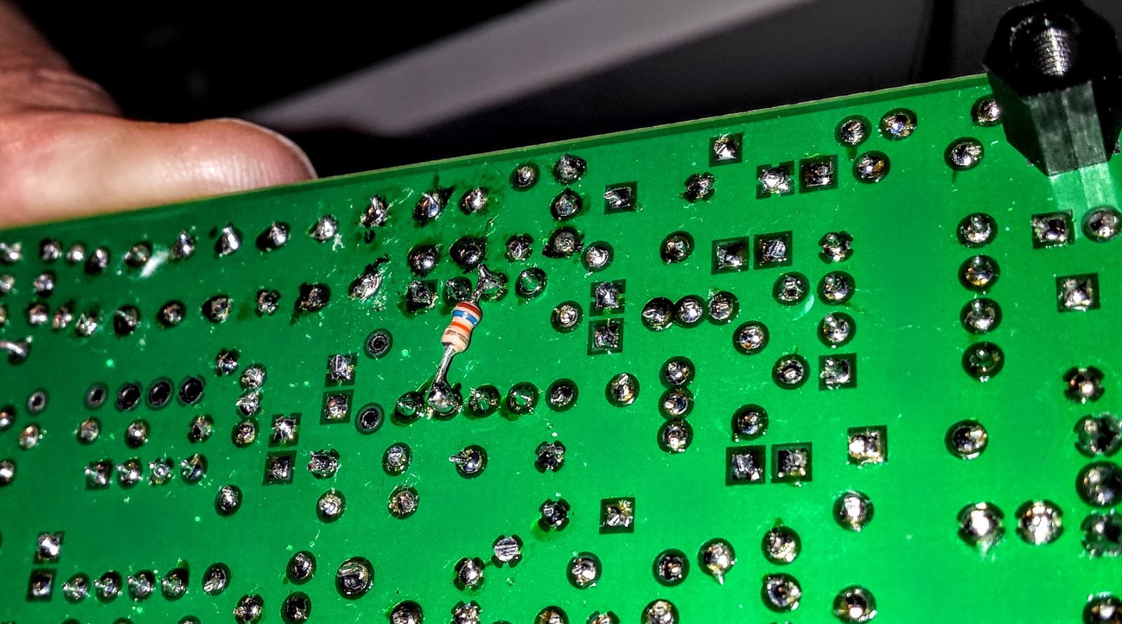 |
| The FIX for all those problems required an extra resistor connected across U5 |
Learning from problems
Being the first person to build a particular version of a kit brings its own set of challenges, especially when you're as new to kit building debugging RF problems as I am. However I'm actually glad the kit didn't work right at the initial build.The process of debugging the board, was a great learning process. I studied the schematics and learned, as best I could, the function of each circuit so that I could better understand how to test it. During the debugging process Diz instructed me that although RF signal generators and scopes are useful you can tell a lot by touching a RF component with an inductive metal object and listening for a buzz or hum from the BFO.
So all-in-all, even though the bug in the board was not due to a error on my part, I'm glad it occurred. I understand more about superhet radio design than I did before and more than if the kit had worked right off the bat.
On the air
After receiving the board back, I hooked up the frequency XCO potentiometer, paddle, command button, audio and output potentiometer and an external speaker. I then connected a 12v battery and heard the 1H2O keyer chip announce itself at power up in Morse "1 W".
 |
| Frequency control pot on the left |
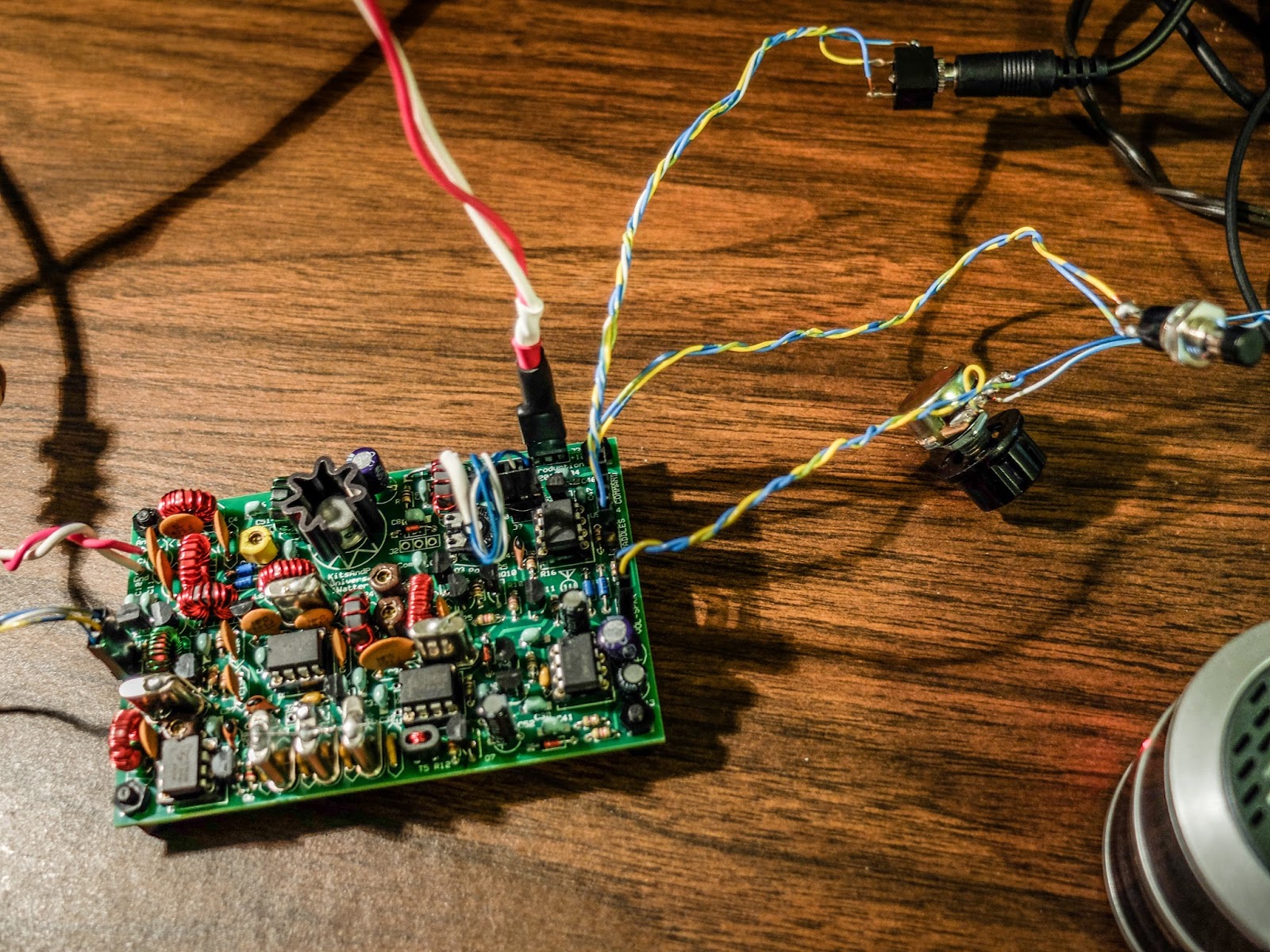 |
| Volume control, output jack, cmd pot and paddle input |
For this first on-air excursion I was using it at the default startup 15wpm keyer speed. You can default the speed higher with a different resistor value.
I have a resistor shrink wrapped and connected in-line to the blue-white wire coiling above the radio connecting to the speed pot terminal. In essence fixing the speed at 15wpm until I add the speed pot.
 |
| Ready to transmit |
 |
| On the air... I was using my paddle out of the photo to the right of the Bug |
First On Air QSO
I tuned around and found a strong station at the end of a QSO near 7030 kHz.
When he sent the final dit-dit I called and WD4AXJ answered my first call. He was in TN near Knoxville, and I received a 559. We chatted for about 10 minutes. Sorry about the blurry video. I thought I'd focused.
After I recorded this video I found an open frequency and sent out my call. Very shortly thereafter KD2FSH answered my call and reported me as 599!
Whoo - hoo. 599 for my little 1Watter 40m.
I was transmitting using my 40m attic antenna. So deed restricted HAMs take note. You can build a one-watt radio and make contacts using your attic antenna. Haha.
You'll hear in the video there is some weirdness going on with the audio derived AGC. It is clamping down sometimes and is worse when I don't have the volume turned up very loud. When I began calling it clamped after every semi-break-in but didn't do it much after that. I'll have to look into that.
The AGC clamping may be a side effect of the increased gain Diz added to the BFO oscillator. I'll ask the forum.
Other than the AGC issue I'm super pleased with the little board. I touched the heat sync a couple of times after transmitting my side of the qso and it was warm but not really hot. It seems as though as long as you have a reasonable match to the antenna the power transistor should be happy.
My next steps are to get it in an enclosure and get it out to the Excalibur antenna site to hook onto that nice 40m doublet we put up a couple weekends ago. I plan to use my efficient little BLT tuner for that purpose. I will do a further review of the feature set on the keyer and record some more qsos for a later review.
Summary
The band was fairly busy and the little 1Watter did a fine job with stations on nearby frequencies. You can hear some getting around the passband but it is not bad at all. I'll do some tests to further define it's selectivity but at first glance it is far better than my old Ten-Tec Century/21.
My calls were answered quickly and I received good signal reports. It didn't sound as though the transmitter was drifting at all during the QSO. That's one advantage of using VCXO in the design. The disadvantage of using a crystal controlled oscillator for the frequency control is limited tuning range. The transmitter only has about a 18 kHz tuning range around 7030 kHz and I don't find many of the SKCC folks around that frequency but it is the QRP watering hole for 40m.
It is possible to shift the frequency with some capacitance changes but I think I'll leave it as is for a time and see how many states I can work.
Just imagine. This little $50 single band kit has good selectivity, a nice built-in keyer with a natural sounding sidetone, and lest we forget... You get a MIGHTY 1 WATT of OUTPUT. What more could a QRP ham need.
That one-watt of output was sufficient for all the QSOs I attempted tonight.
So lower your power and raise your expectations
72/73
Richard, AA4OO
UPDATE: 04/01/2016
I am still having the AGC pumping issue and others on the list have reported similar issues but only on receive. It happens to me when I key unless I turn up the volume very high. I did get it installed in a case but I still need to wire up a real power connector rather than using alligator clips.
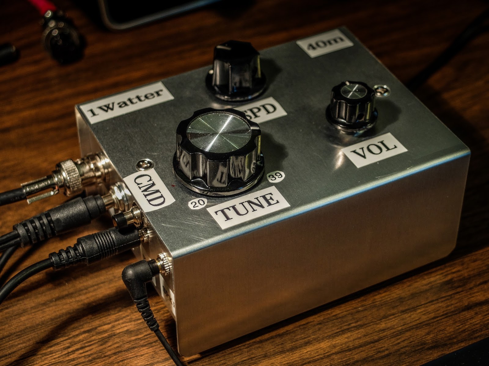
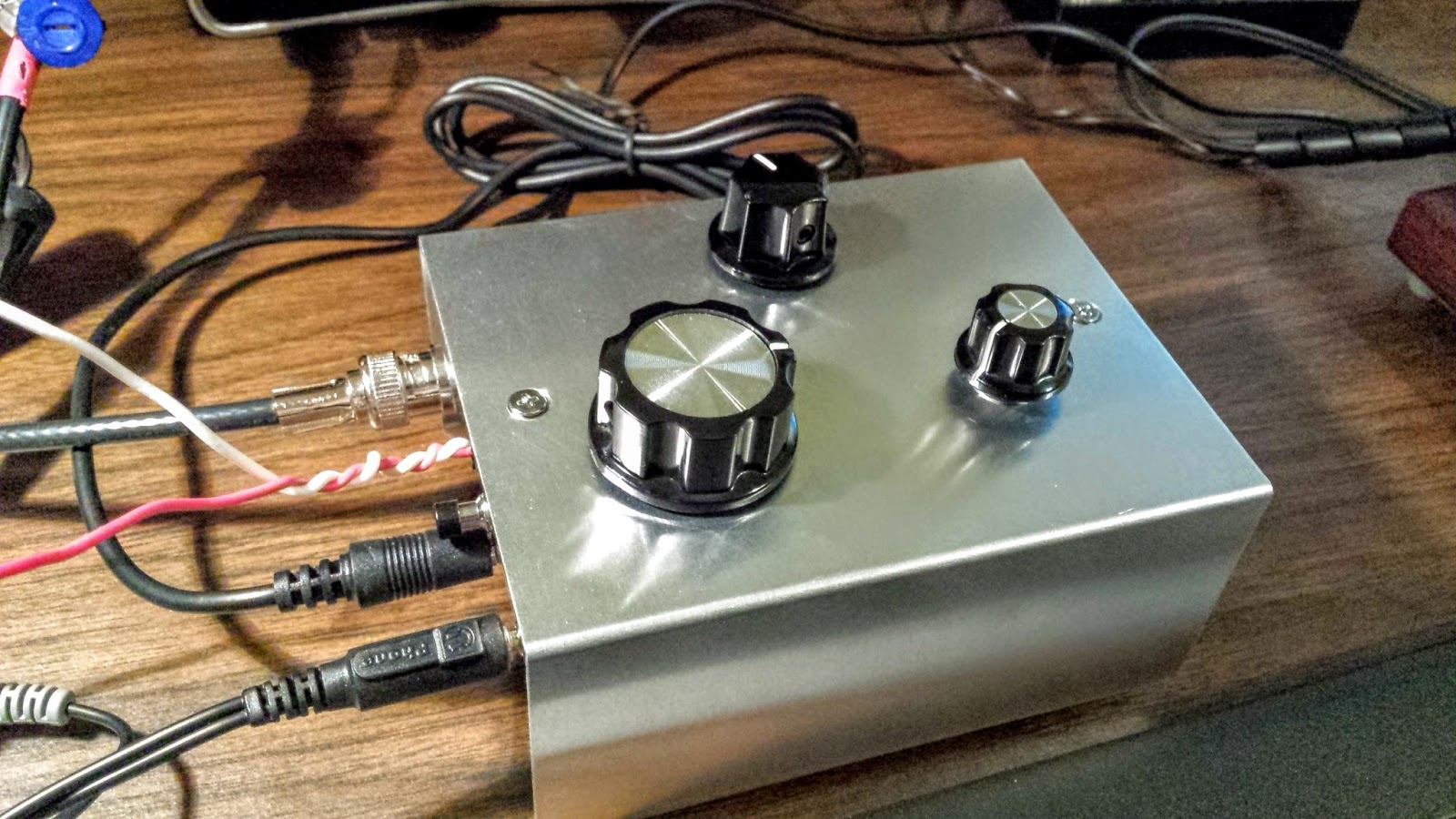 |
| !Watter installed in a case |
UPDATE: 04/05/2016
After doing quite a bit of reading I learned that the LM386 op-amp used in the 1watter is rather notorious for audio oscillations. There are a number of suggested fixes. I went with a 4.7uf cap connecting Pin 7 on U6 (the LM386) to ground. That hasn't totally resolved the issue but it's much less pronounced now.
I have it in the case with all the proper plugs now (see below) so I'm happy. I've been making QSOs every day with it and it continues to amaze me and the stations that work me. It is stable as a rock with regard to frequency and the large knob with the single turn 10k pot seems to work well for tuning. I have enough control to vary the frequency slightly without having to turn it too much. The tuning range is only about 20kHz so just 3 frequency markers are plenty to let me know what frequency I'm near. The selectivity is just fantastic for such a simple little radio. Diz has created an inexpensive winner.
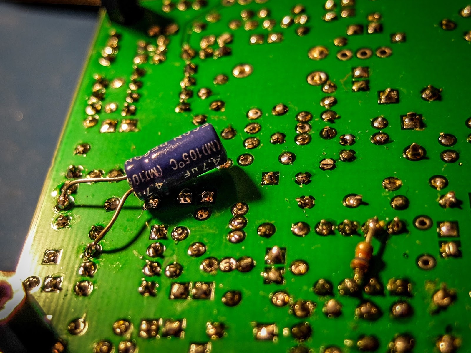 |
| cap fix for LM386 oscillations |
 |
| 1Watter in enclosure with all the proper connectors for the case |
BLT+ Balanced line tuner at Excalibur
Another portable test of the BLT+ tuner
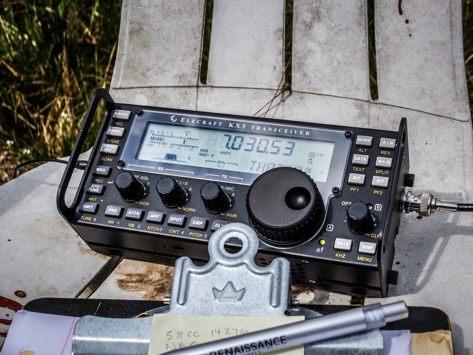 |
| KX3 operating on internal battery. What a fantastic portable rig. |
I took the BLT+ balanced line tuner out to the Excalibur antenna site to try it out on the doublet antenna that we put up last Saturday. This was the first test of that antenna (40m and 80m using a common feedpoint).
I didn't have much time today and after the first QSO it started to rain so I packed up and left before getting as much documented as I would have liked. I apologize for not recording the actual tuning process and the subsequent QSO.
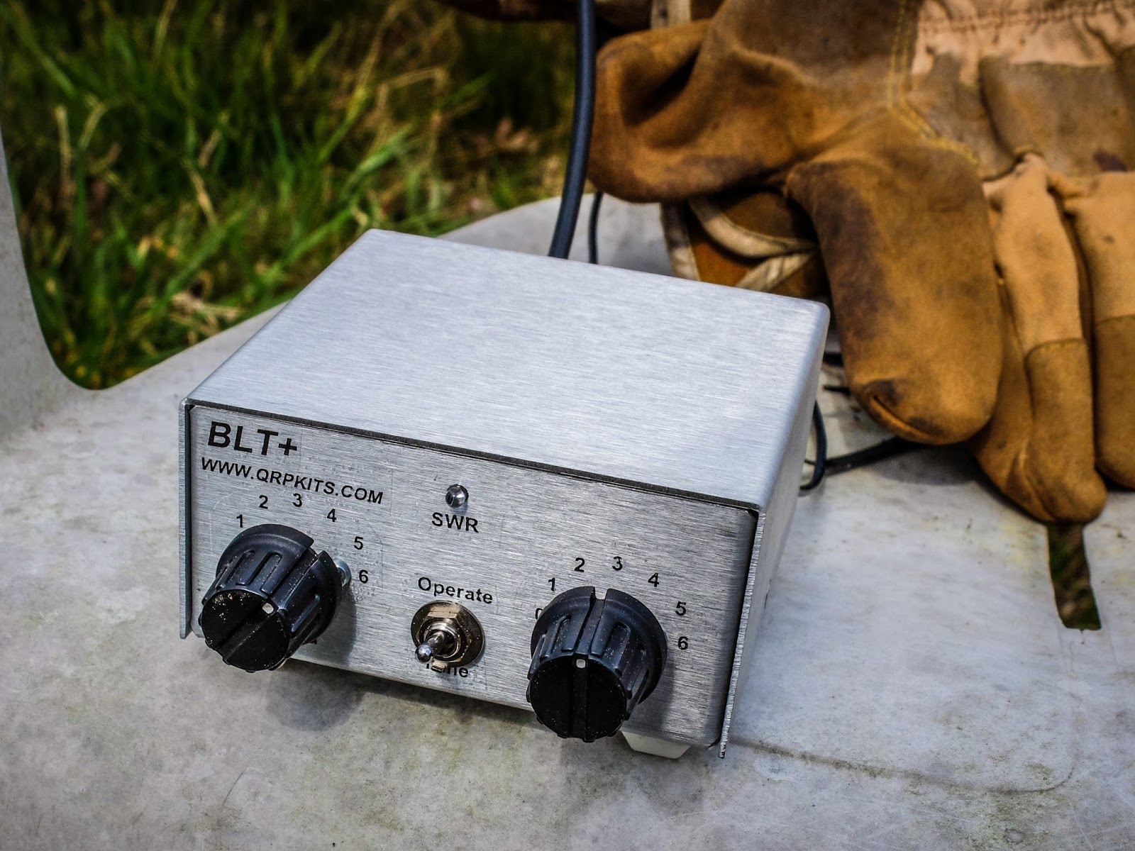 |
| BLT+ connected to open wire line (under the gloves) going to ta 40m Doublet at 65ft |
I had the KX3 operating using its internal batteries and outputting 2w. I was running 2 watts because that is the most efficient PA mode for the KX3.
I used the BLT+ to tune the 40m/80m doublet. Balanced line antennas perform better with a tuner designed for balanced line and this was a good test for both the tuner and the new antenna.
I used the BLT+ to tune the 40m/80m doublet. Balanced line antennas perform better with a tuner designed for balanced line and this was a good test for both the tuner and the new antenna.
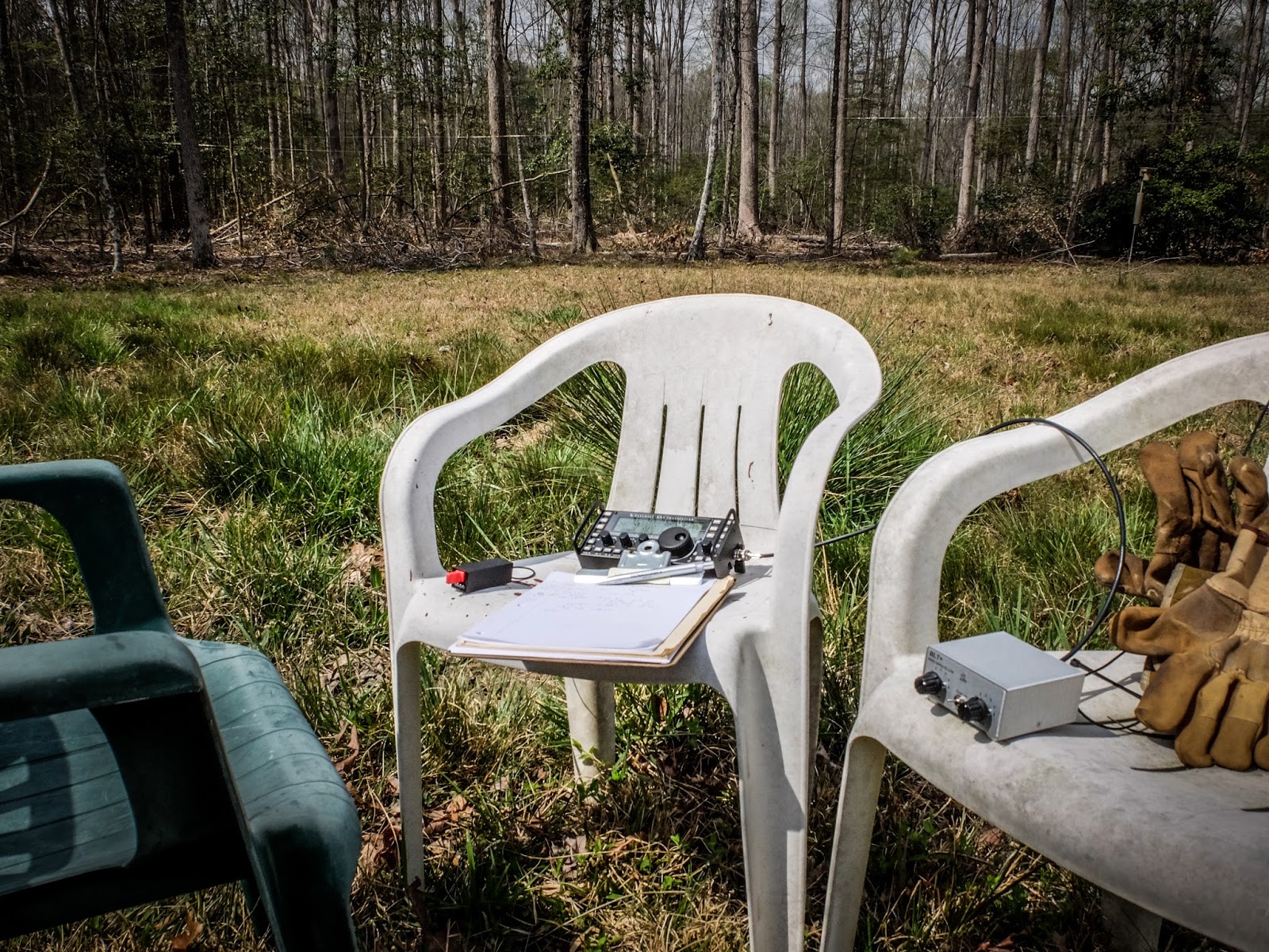 |
| Portable shack, courtesy of three plastic chairs |
I quickly matched the doublet using the BLT+ using the lowest impedance setting which is also the most efficient. I was glad to see that the BLT SWR LED indicator is bright enough to be seen in direct sunlight. I was wondering about that but you can definitely tell when it dims even in direct sunlight.
Performance
After quickly tuning up I sent my call two times and was promptly answered. The other station was running a Flex 6500 into a KPA500 and a OCF Windom at 50 feet.
He reported me as 559, while he was a 599. He was running a new KPA500 amp at 500w so we were a bit mismatched on power.
Interestingly the difference in 2w and 500w exactly matches the 4 S-Unit difference in our reports if you do the math (each increase in an S-unit requires quadruple the power).
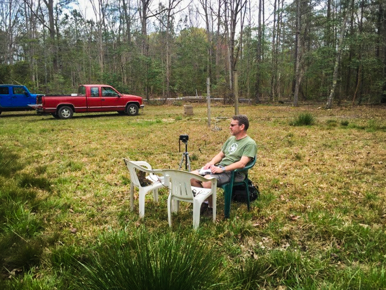
AA4OO sitting back and listening to the QSO
Paul AA4XX kindly snapped some pictures while I was listening to the other operator. This is the Excalibur antenna site but the shack is outside the photo.
The Doublet's feed line has not been brought to the shack yet so I was just sitting under the antenna. The open feed line is running along the ground for a bit which certainly didn't help the signal but we haven't installed the posts to carry the feed line over to the shack and I was too lazy to move the chairs far enough away to keep the feed line in the air.
In the foreground is some saw-grass common on the NC coast. I'm not sure why it's growing this far inland.
 |
| Portable shack at the Excalibur antenna site... The Doublet is 65 feet above my head |
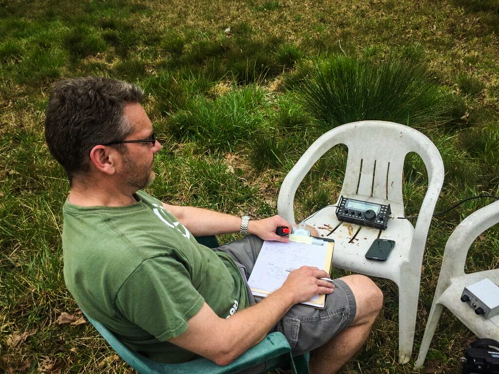 |
| Waiting my turn in the QSO... holding the Palm Single Paddle. BLT+ tuner in the chair to the right |
Video
Here is a brief video showing how the BLT+ is connected to the Doublet...
Summary
The little BLT+ performed great with both balanced line antennas I've tried. It is easy to use and allows me to use my KX3 with balanced feed line antennas now. I encourage you to build the kit from Pacific Antenna / QRPKits.com .
That's all for now
So lower your power and raise your expectations
72/73
Richard, AA4OO
The N3ZN Iambic CW Paddle
Behold… mechanical beauty
 |
| N3ZN ZN-QRP Iambic Paddle (sporting my new call sign) |
I re-entered the amateur radio hobby in the summer of 2015 after a bit of a hiatus. To get my General license in 1996 a Morse code proficiency test was required. At that time I had purchased a cheap MFJ practice key and a used version of the ubiquitous Bencher BY-1 paddle. My Bencher was in reasonable shape but I just never became comfortable with it. It always felt a bit imprecise to me and I wasn’t happy with the width and size of its paddles.
I’ve Got the Power
Elecraft W1 Power Meter
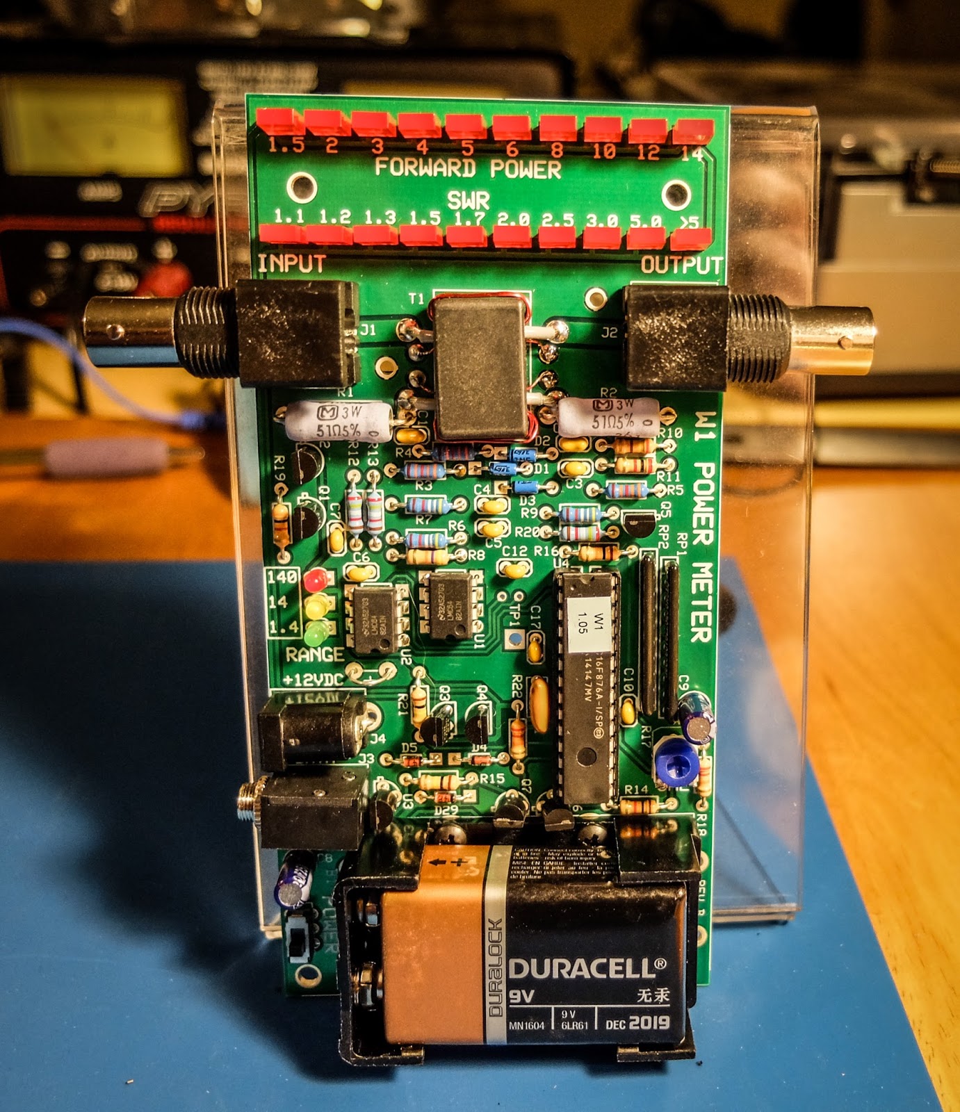
The Elecraft W1 is another fine mini-module kit from Elecraft. It is an auto-ranging power meter measuring as little as 150mw up to 140w. The 150 milliwatt to 1.4 watt range is an especially nice feature for QRP'ers.
 |
| Elecraft W1 Power Meter |
Building
I am new to building kits. My first kit was from 4-State QRP (Regen Receiver). This is my 4th Elecraft kit. The instructions are very detailed and easy to follow and I especially like that they give you the resistor color and capacitor identification right there in the instructions without having to refer to a data sheet somewhere else in the documentation.
All the parts come in a single bag so there is a bit of sorting that you need to do when you receive it. I use a big egg carton to sort and inventory the parts so that I can find them more easily.
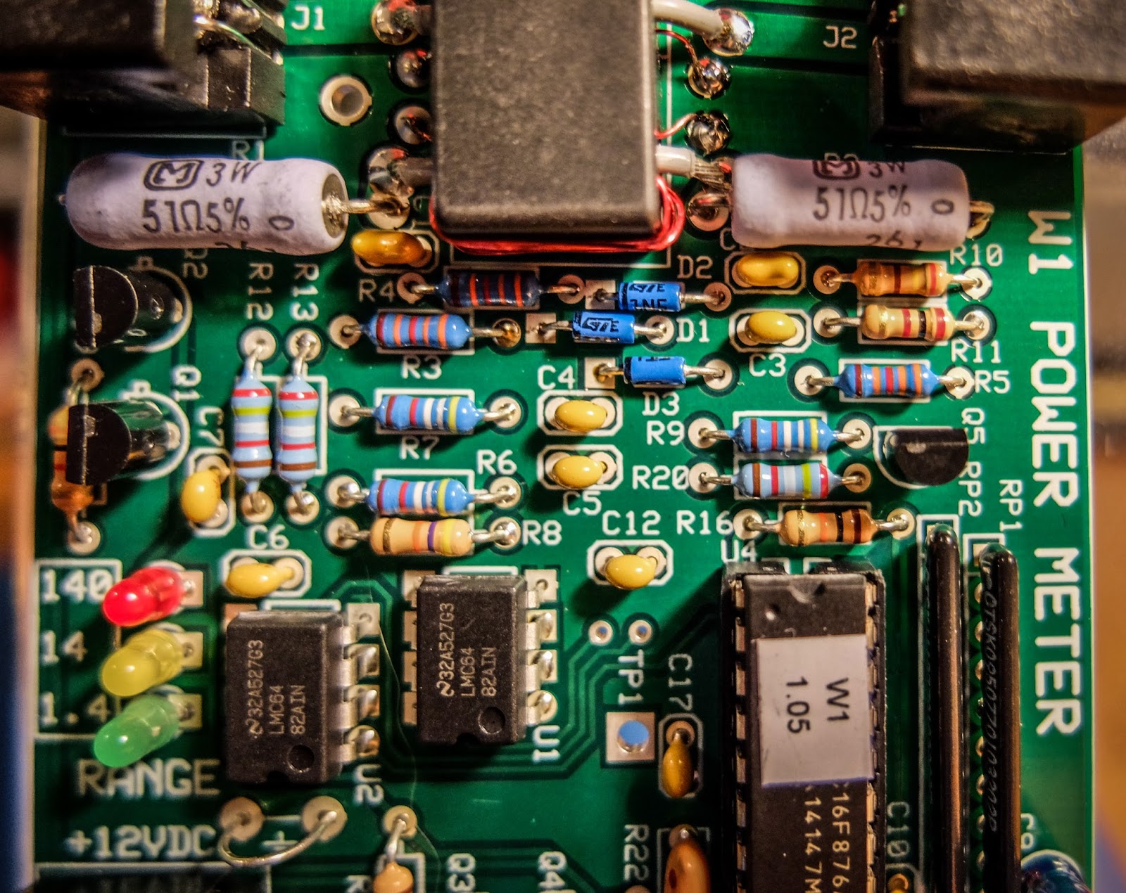
This kit was a bit more involved than the other kits I've built from Elecraft. It has a binocular toroid which is fiddly to wind, 3 ICs and a couple of resistor packs. Lots of soldering. The most tedious parts to solder are the tiny transistors. Those solder pads are really close together for someone new to soldering like me, but I took my time and everything turned out ok. I worked on this kit a little at a time over 3 nights. If you can follow instructions and have a steady hand you should be fine.
The kit has some ESD sensitive parts so you'll want to be able to properly ground yourself and your equipment. Make sure your soldering iron is ESD safe and that you are grounded.
Lastly, final calibration is performed using just a multi-meter.
Build options
The meter can be built in a number of different configurations depending on how you plan to use it. The battery holder and BNC connectors can be installed on the top or bottom of the board and the BNC connectors can even be oriented vertically on the back side of the board. If you plan to use it in an enclosure give some thought to the location of the battery holder and BNC connectors before you get to that part of the build.
I plan to use some stand-offs to mount it to the front of an acrylic photo frame that I already had.
 |
| An acrylic-angled photo frame can make a homebrew stand |
Operation
The meter can operate from a 9V battery or from an external power supply via the barrel connector on the side. There is a small power switch at the bottom left of the board.
The top row of LEDs indicate power for a given range. The 3 LEDs mid way down the board to the left indicate the current power range. The range can be automatic or set via a command through the serial interface.
The ranges are:
- 150 milliwatts to 1.4 watts -- Green LED
- 1.5 watts to 14 watts -- Yellow LED
- 15 watts to 140 watts -- Red LED
Computer interface
There is a 1/8" stereo jack below the power connector that provides a serial interface to a computer. There is a command set for interacting with the meter as well as a sample application available on Elecraft's site that allows a number of settings to be modified such as peak hold and saved to the meter.Elecraft sells a $15 serial interface cable kit. What they don't tell you is that it has a DB-9 connector rather than a USB connector. I don't even have a computer with a DB-9 serial port so buyer beware. You may want to skip their kit and build your own. I happened to already have a DB-9 to USB converter but I'd preferred their kit to provide a USB connector.
Demonstration
Photos
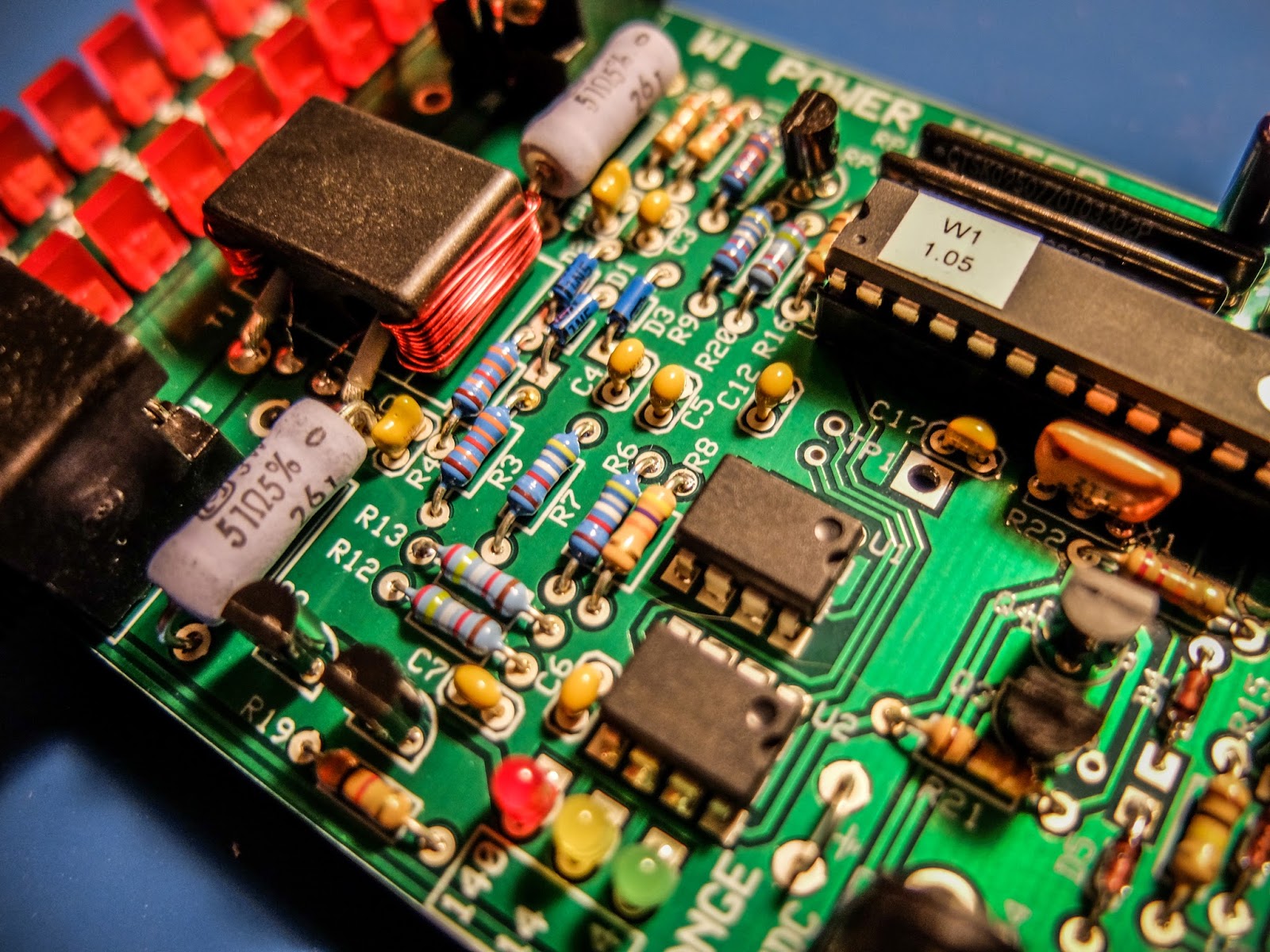 |
| 3 ICs to solder and toroid winding... lots of fun |
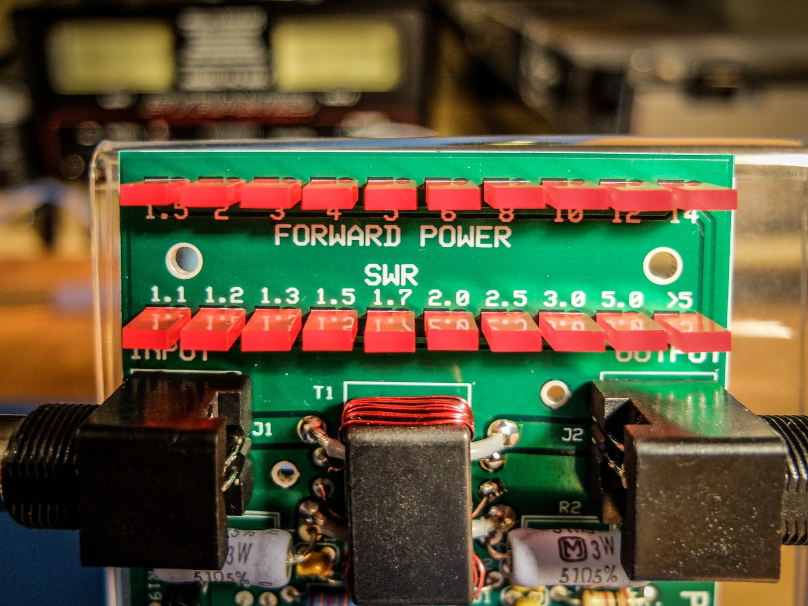 |
| LEDs indicate power in each range and SWR |
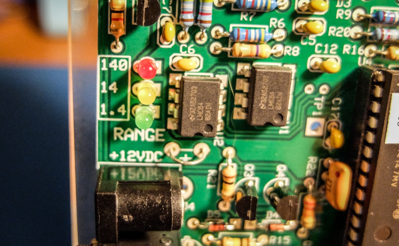 |
| LEDs indicate the power range being displayed |
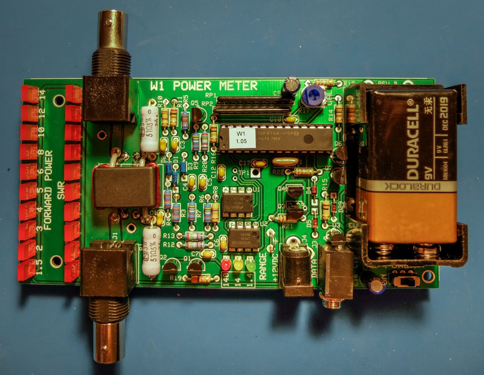 |
| Elecraft W1 Power Meter |
That's all for now
So lower your power and raise your expectations
73/72
Richard, N4PBQ


