 |
 This is not the wattage you’re looking for… move along
Getting hot under the collector/base junction
Where did my power go?
My Elecraft W1 power meter has been absent from the antenna chain for a while due to a jumper cable shortage when I last reconfigured my shack. But now the W1 meter is back in the chain and it revealed something a bit worrisome about the 1Watter transceiver...
My Elecraft W1 power meter has been absent from the antenna chain for a while due to a jumper cable shortage when I last reconfigured my shack. But now the W1 meter is back in the chain and it revealed something a bit worrisome about the 1Watter transceiver...
I've had a bunch of QSOs using the 1Watter both in the shack and in the great outdoors. The 1Watter is my first home built transceiver (albeit from a kit) and has been a great learning experience. It is called a 1Watter (or 1H2O as Diz calls it) because it nominally produces an output of 1 watt.
The Elecraft W1 power meter is a nice, inexpensive QRPp to QRO meter because it measures from 150 watts all the way down to 150mw.
The little 1Watter transceiver does indeed produce just a hair over 1 watt when it's first powered up. Tonight I tossed my call out on 7030 kHz and was promptly answered by N4DR up in Maryland. He was running a YOUKITS TJ5A at 5w. When we started the QSO my W1 meter showed that my 1Watter was outputting between 900mw and 1w to my mighty attic antenna.
Then by the second exchange in the QSO I noticed my output power dropping down to 700mw. By the end of our ragchew my 1Watter output had dropped to 500mw.
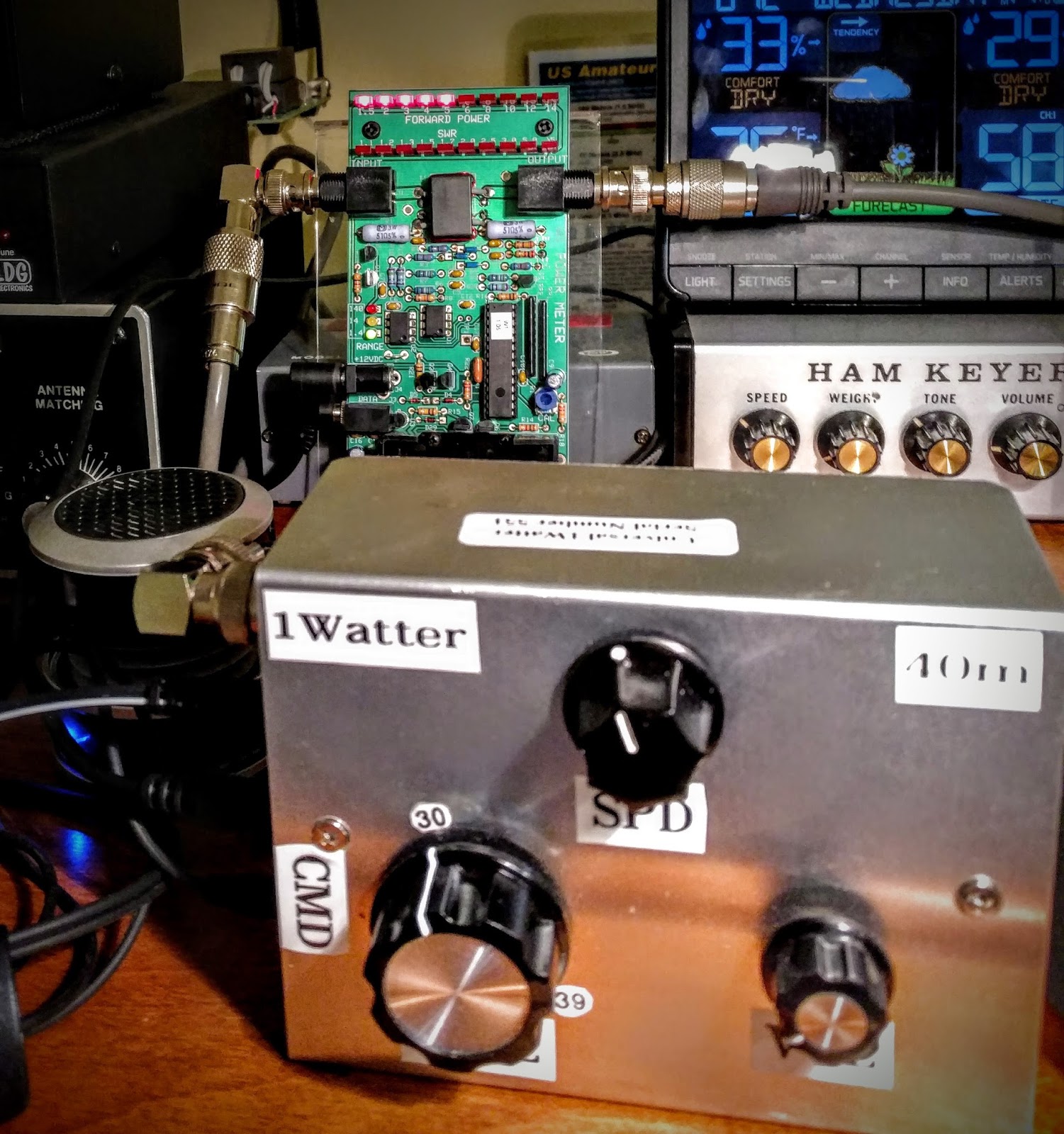 |
| Power meter in background showing 500mw by the end of the first QSO |
As I ended that first QSO I was called by another station (AF4YF) who was running a 2 watt homebrew xcvr. And by the end of that QSO the 1Watter was producing less than 300mw. I felt that some investigation was in order.
Heat is the enemy
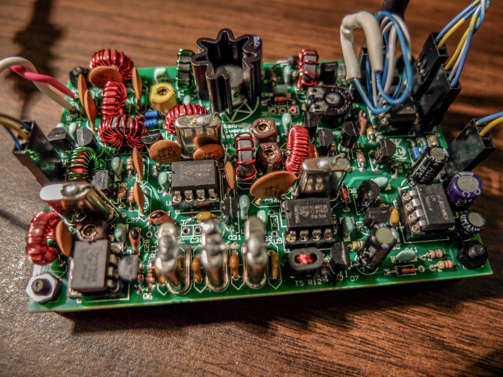
The 1Watter uses a 2N5109 NPN RF transistor for a final. Transistors really are not fans of heat.
The maximum power output available from a power transistor is closely linked to temperature, and above 25°C falls in a linear manner to zero power output as the maximum permissible temperature is reached.
My 1Watter kit included a friction fit heat sink, seen at the top of the photo below. But apparently this heat sink either saturates quickly or doesn't have sufficient surface to conduct away the heat. My enclosure is not vented but it is alumunium and I don't feel any appreciable temperature rise above ambient so I don't think venting is in order yet.
I allowed the 1Watter to rest for 30 minutes following the QSOs, still powered but not transmitting. That only resulted in the output power getting back into the 700mw range. I'm considering increasing the bias to start with a higher transmit power so that it will maintain 100mw but I'm afraid of destroying the transistor. I might also try some conductive paste but it's messy and I'm not sure it will help if it can't be pressed between two surfaces.
I'd appreciate any constructive suggestions. I'm still a noob at this electronics stuff.
But the real moral of the story is...
 |
| Band conditions on the evening of this QSO |
So as I sat here wondering why my 1 watt radio was only producing a 1/2 watt now, I reminded myself that I was having extended QSOs using a (now) 500mw radio with other QRP operators (5w and 2w). I was also using my attic antenna, not some multi-element beam on a tower. Band conditions on 40m were also a limiting factor tonight (see snapshot at right).
These were not simply swap 599 TU QSOs, we were exchanging information on multiple go-rounds with solid copy.
So if you're reading this blog you likely have some interest in QRP. Hopefully this is just yet another reminder that we often don't need as much power as we think we do for communications. I was getting discouraged this summer due to the decreasing sunspot cycle and thinking "I'm gonna need to operate QRO more and likely get a real antenna put up in my yard".
But it's times like this with my 1Watter that keeps reminding me to lower my power and raise my expectations.
But it's times like this with my 1Watter that keeps reminding me to lower my power and raise my expectations.
So lower your power and raise your expectations...
72 / 73
Richard, AA4OO
One Response to “This is not the wattage you’re looking for… move along”
Please support our generous sponsors who make AmateurRadio.com possible:
 Ham Radio Deluxe |
 W5SWL Electronics |
 Ham Radio Prep |
 KB3IFH QSL Cards  Hip Ham Shirts  HamRadioAuctions HamRadioAuctions Reliance Antennas Reliance Antennas Enigma Shop Enigma Shop |  morseDX  Ni4L Antennas  R&L Electronics R&L Electronics antennas.us antennas.us QRV QRV |
- Matt W1MST, Managing Editor

Hello Richard, Here’s my $0.02. First get a spare 2n5109 (for just in case). If you don’t have, get some liquid flux and a pinpoint dispenser (MCM, Digi-Key, Mouser etc have it). Finally get some copper foil — I get it from a craft store.
Make 4 or 5 “v” shaped pieces of copper foil around 3/4″ high. Solder the points of the V’s on to the sides of the 2n5109, spaced more or less evenly around the perimeter, and with the extra part of the v’s sticking up. If you tin the foil and the case of the transistor using the flux to help the solder flow, it will make soldering the V’s to the transistor much easier.
It will look ugly but it will give you increased heat flow out of the transistor. The 2n5109’s are not indestructible but are very rugged. I used one as an I.F. amplifier in a 222 MHz to 10M transverter and it was oscillating. It got so hot that the case turned dark gray from oxidation — and it didn’t fail.
If you do overheat and destroy a 2n5109 its no trajedy – they’re only $2 or so.
GL & 73, Lenny W2BVH