Posts Tagged ‘Altoids’
 Better with SMA
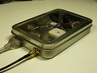
I had some trouble closing the lid on the “Just good enough 10 MHz reference” due to the size of the BNC jack. Therefore I changed it to an SMA (SubMiniature version A) female jack. A thin cable connects it to the K3’s SMA input and there is no need for any SMA-BNC adapter on that end.
At the same time I moved the GPS antenna to a more central location in the tin, in the hope that the walls of the tin would interfere less with GPS reception. That’s the theory anyway, if it matters much in practice is a different story.
 Actually, I think I’m going to use SMA more often with these clear top tins and also Altoids tins. They take up much less space and are easier to install and to work with.
There aren’t any high power applications for circuitry in such tins, so I cannot so any reason why the SMA won’t work just as well or even better than the BNC.
 First 475 kHz WSPR decoding
Tonight I made the first successful decoding of WSPR on the 630 m band. What inspired me was all the talk on the Elecraft reflector on the new synthesizer which in addition to having less phase noise, also allows the K3 to go below 500 kHz. I don’t have that synthesizer, but the discussion reminded me of the low frequency converter I built many years ago. It converts 0-1 MHz to 14-15 MHz. Using the KXV3 transverter interface of the K3 it was easy to interface and get up and running.
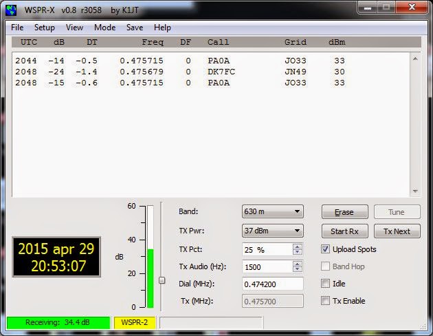
The first signals I decoded are shown in the water fall above, and their origin in Germany and the Netherlands is shown in the next figure.
According to WSPRnet, PA0A’s 2 Watt transmitter is 784 km away from me, and DK7FC’s 1 Watt is 1164 km away.
The converter is based on a 74HC4053 switch used as a mixer with a 74HC04 for a 14 MHz oscillator. It is based on SM6LKM’s design, but with a different oscillator frequency and a simplified output filter. It is one of many small projects that I have built in Altoids tins. The antenna used was my trusty old 80 meter horizontal loop with a 4:1 Elecraft balun.
Perhaps the next step is to finish the 475 kHz filter of my Ultimate 3 WSPR transmitter and see if others can receive me? That is going to be more of a challenge antenna-wise.
 First 475 kHz WSPR decoding
Tonight I made the first successful decoding of WSPR on the 630 m band. What inspired me was all the talk on the Elecraft reflector on the new synthesizer which in addition to having less phase noise, also allows the K3 to go below 500 kHz. I don’t have that synthesizer, but the discussion reminded me of the low frequency converter I built many years ago. It converts 0-1 MHz to 14-15 MHz. Using the KXV3 transverter interface of the K3 it was easy to interface and get up and running.
The first signals I decoded are shown in the water fall above, and their origin in Germany and the Netherlands is shown in the next figure.
According to WSPRnet, PA0A’s 2 Watt transmitter is 784 km away from me, and DK7FC’s 1 Watt is 1164 km away.
The converter is quite simple and is based on a 74HC4053 switch used as a mixer with a 74HC04 for a 14 MHz oscillator. It is the design of SM6LKM, but with a different oscillator frequency and a simplified output filter compared to his. It is one of many small projects that I have built in Altoids tins.
The antenna used was my trusty old 80 meter horizontal loop which has been the main work horse for making my 8-band DXCC (more than 100 countries on all bands 3.5 – 28 MHz) possible. It is fed with ladderline into a 4:1 Elecraft balun in the shack.
Perhaps the next step is to finish the 475 kHz filter of my Ultimate 3 WSPR transmitter and see if others can receive me? That is going to be more of a challenge antenna-wise.
 Show off your project in a clear top tin
I first learnt about these tins from the 4 State QRP Group. They advertised them as “Clear Top Enclosure – An Altoids On Steroids. Do you need an enclosure slightly larger than an Altoids tin? Would you like to see your project after building it, instead of hiding it? If so, this enclosure is for you!”
The rectangular hinged tins are no longer sold by the 4 State QRP Group, but I was able to buy them from Specialty Bottle via a friend of mine in the US (their minimum order for export was too high for me).
My projects from left to right and top to bottom are:
- Component tester (transistors, capacitors, resistors, inductors, equivalent series resistance) from Ebay based on this open source design.
- Direct digital synthesis (DDS) generator that generates RF from 0 to 20 MHz
- Ultimate2 QRSS kit transmitter from G0UPL
- 3.5 MHz Pixie transceiver
- AVR Butterfly Morse keyer from KD1JV
- Softrock Lite 6.2 SDR (Software Defined Receiver) in an enclosure which originally housed a 4.5″ USB flash disk.
 The simplest possible AM transmitter
Here’s a design for a 1 MHz amplitude modulated (AM) transmitter. I’ve been looking a while for something like this, a simple short range AM transmitter for the medium wave band, as I needed something for demonstration of my collection of old radios.
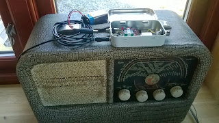
The result is the AM transmitter shown here in an Altoids tin on top of a Radionette Kurér radio. This is a portable tube radio from the 1950’s. Several hundred thousands were produced, and it was exported from Norway to 60 countries. It is still popular among collectors.
The transmitter is as simple as it gets. The heart of it is a 1 MHz crystal oscillator in a can. Its 5 Volt power is modulated via an audio transformer, one taken from the output of a transistor amplifier (primary 147 ohms – secondary 3 ohms). I drive the modulator from my cell phone into the low resistance side of the transformer and get good audio when the phone’s volume is set to maximum.
The design was inspired by one from Instructables, but mine also has a 78L05 5 Volt voltage regulator and a red LED in series with the power supply. It indicates that the battery is plugged in. In total the transmitter draws 4.4 mA at 9 Volts. The input power to the oscillator is less than 5 Volts * 4.4 mA or in the order of 20 mW. The power output is just a fraction of that. I have tested it with a 1.5 m wire hanging down behind the built-in frame antenna in the back of the radio with good results.
This is really just a modulated marker transmitter as I have briefly described on this blog before, and the square wave will have harmonics of 1 MHz over the entire short wave band. Some of these frequencies may propagate really well, so if used with a longer antenna, it should really have an output low pass filter to prevent that.
I’m not totally happy with this design, despite its simplicity, though. If I could, I would rather like to transmit in the long wave band at 216 kHz. This is the old frequency of the Oslo transmitter which ceased operation in 1995. As a member of the Norwegian Radio Historical Society, I am allowed to use that frequency with a transmitter input of 0.5 W for demonstration purposes.
For other frequencies, one simple alternative is a standard canned oscillator at 1.288 MHz. I also believe some of the Silicon Labs oscillators can be used in order to get an adjustable frequency, but I haven’t tried that myself.
But until I find a suitable frequency source at 216 kHz, I’ll stay with the 1 MHz alternative at a mere 20 mW. It is in line with the best principles of KISS (keep it simple stupid) or with Occam’s principle : “It is vain to do with more what can be done with less“, i.e. the QRP philosophy.


