Posts Tagged ‘630m’
 FCC Opens 630/2200 Meters Amateur Band; Pre-Registration Required!

Yes, the headlines read, “FCC OPENS 630/2200 METERS TO AMATEUR USE AS OF OCTOBER 16, 2017; PRE-REGISTRATION REQUIRED.”
The FCC has authorized amateur radio use of the 630 and 2200-meter bands, effective October 16, 2017, providing registration procedures have been followed and no objections are received within 30 days.
The PLC (Power Line Communications) database is live and hams may begin registering immediately. They may begin operating on 472 kHz (630 meters) and 137 kHz (2200 meters) as early as October 16 if they register today and receive no objection in the next 30 days. Hams may not operate on the bands without going through this process.
Please fill out the UPC Form, today, to register your station, even if you don’t have any plans on transmitting on these new bands.
It is imperative that all amateurs register, even if they don’t plan to use these bands in the near future, as the FCC rules prohibit UTC (the Utilities Technology Council) from deploying PLC in these bands closer than one (1) kilometer from registered stations. Registration now will protect your ability to use our new MF/LF bands in the future.
VE7CNF / 630m Mobile … almost.
 |
| If you think 160m mobile is a challenge... |
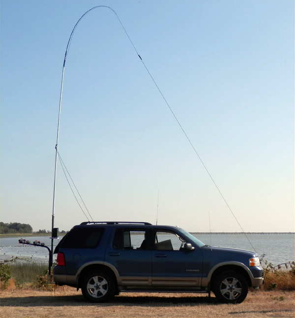
Hot on the heels of his recent 630m maritime adventure, Toby (VE7CNF), continued to demonstrate the flexibility of his small 20W 630m portable system with an afternoon of fixed 'mobile' activity from his vehicle.
Local 630m op's in-boxes received a surprise alert on Tuesday:
"Are any of you available on Tuedsay for a 630m land mobile test with VE7CNF/7?"
Toby set things up at Sea Island's Iona Regional Park, situated on the ocean's edge just north of Vancouver International Airport. This gave him a good shot to several of the local 630m ops around the local region.
When Canadian amateurs first approached RAC and Industry Canada for a slice of spectrum near 500KHz, the main goal was to secure a frequency range that would support excellent groundwave propagation for a possible future emergency data network. Whether this will ever happen or not remains to be seen, but Toby's afternoon outing, along with the recent 630 marine mobile activity certainly helps to demonstrate the potential for the band to provide reliable signals with relatively small antennas and low erp.
Toby's basic transverter is rather unique in that the transmitter's FET power mixer also passes signals backwards to function in the receive mode:
"I’ve developed a 630m band linear transverter that produces 30W of transmitter power. It has no power amplifier and draws only 175 mA from a 12V power supply. It works for both transmit and receive with no T/R antenna relays or switching circuits.
I’ve used a bidirectional high-power mixer circuit to directly take 100W of power from a 160m band transceiver and produce useful output power on 630m. For receive, 630m signals can pass backwards through the circuit and are up-converted to 160m.
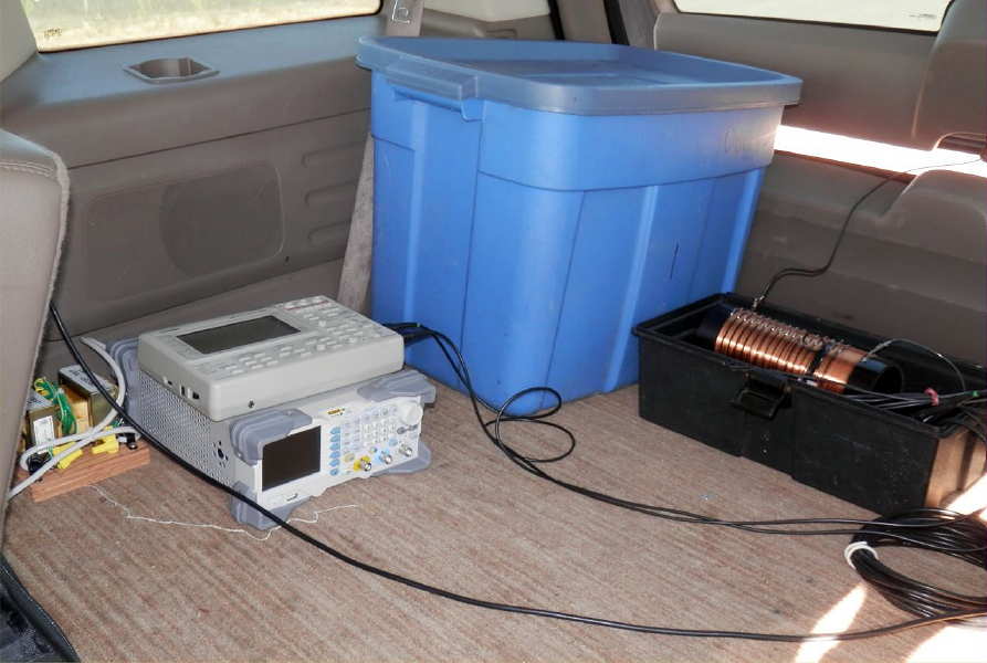
My transverter is actually the small box on the dash above the steering wheel. The gear in the back near the variometer is used only during setup to resonate the antenna. It's a signal generator and oscilloscope. The AC transformers are just an isolation transformer that I need to make the test equipment work with my 12V-to-AC inverter."
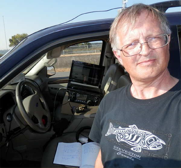 |
| Toby VE7CNF/7 at Iona |
On 475.0 kHz CW I managed to work Roger VE7VV (CN88il, him 529, me 579) and Jack VA7JX (CN79kv, him 569, me 579). I heard Steve VE7SL (CN88iu) at 599 briefly, then he had a problem and we didn't complete a QSO. He gave me 599 later by email.
The antenna is about 24 ft high and the fishing-rod-and-wire top load is pulled forward about 8 ft. The matching circuit is a loading coil, variometer, and autotransformer. My Tx power was 20W TPO and estimated EIRP 75 mW. The rig was my home brew transverter with an IC-7410."

"After CW I ran WSPR for a while, 23:42 to 00:08 UTC (4:42 to 5:08 pm local). WSPRnet lists my spots as my home QTH CN89ng, but I did have CN89jf entered in WSJT-X. I got spots from WI2XJQ -17, VE7BDQ +14, VE7AB +6, VE7VV +1, W7IUV -26, WH2XGP -30 dB. I also decoded WSPR from VE7VV +7 and VA7JX +9 dB."
Our 'new' band continues to demonstrate its ability to offer exciting opportunities to experimenters, home-brewers and DXers alike and for those with the creative imagination to push new boundaries, who knows where one of the first frequency ranges to be used by amateurs back in the 20's might eventually take us.
I can visualize, at some point in the future, the usefulness of a province-wide 630m emergency comms network utilizing a basic 'grab and go' system based on much of Toby's demonstrated work.
If you are a Canadian amateur why not join the fun on 630m now? U.S. amateurs will be arriving shortly and when they do, things should be getting even more exciting on the new band!
A 630m Maritime Adventure
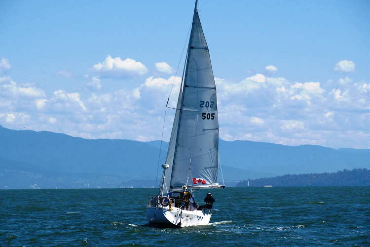 |
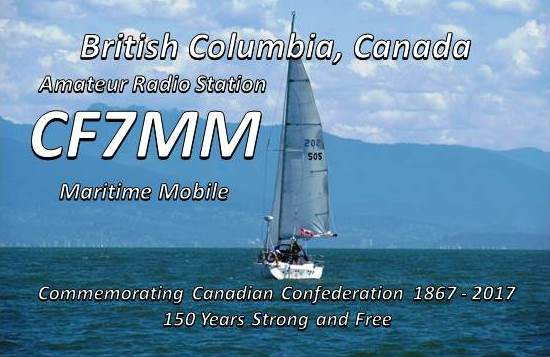
| HAKUNA MATATA |
Crewed by Mark (VA7MM) and YL May (VA7MAY), Toby (VE7CNF) and XYL Nancy, the 31' Benateu recently completed a 14-day circumnavigation of Georgia Strait's Gulf Islands. This is a yearly adventure that has been successfully completed for the past few summers and looks as though it may now be an annual tradition.
Normally, the crew kept up regular radio contact on HF as well as on VHF when possible but this year saw a major departure.
In previous summers, near the end of the voyage, the crew has always visited us here on Mayne Island for an afternoon of vittles and libation before heading for home. There is always a good amount of time spent recalling the past-year's radio activities, winter projects and reminiscence of the 'good old days'. Last year, just as the party was ending, I jokingly suggested that 'next year', it would be cool to work them from the boat on 630m.
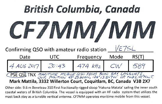
Although there was no immediate commitment, I knew that the seed had been planted, and with three of the four crew being engineers, I suspected it might be hard for them to resist, and ... just before departure, the local bunch of 630m ops were put on alert to be watching for CF7MM/mm on 475 kHz CW as they would be attempting to work us from three different overnight anchorages during their summer voyage!
Evidently Toby had been working quietly during the winter to make this become a reality. Here are some pictures of the system along with Toby's (the system's builder) comments.
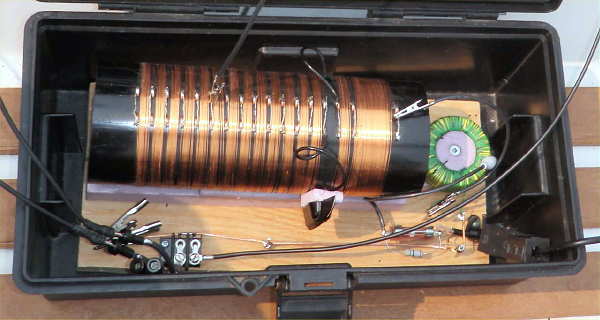 |
| Variometer and matching transformer |
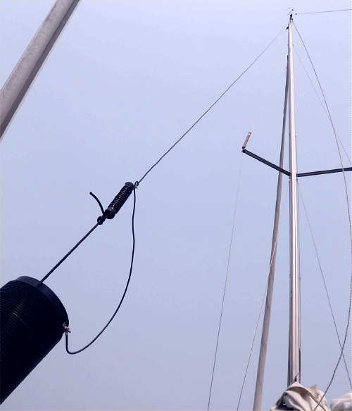 |
| Wire vertical and loading coil |
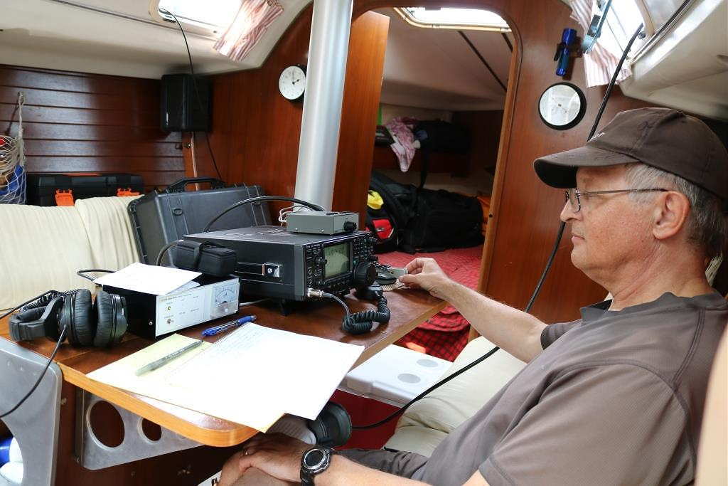 |
| Toby (VE7CNF) working the pileups! |
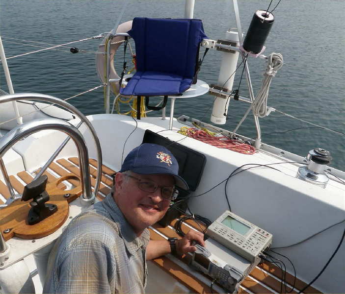 |
| Tuneup |
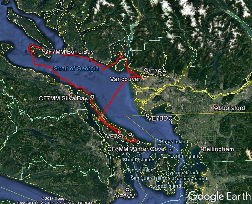 |
| The route, heading north from Vancouver |
Some of the contacts are shown below. Note the transceiver is not really on 160m ... it's just the i.f. for my 630m transverter!
I was impressed with the strength of ground wave signals given the low transmitter powers and EIRP's well below 5W. Received signals ranged from S1 to S9+10dB and copy was easy for all QSOs. QSO distances ranged from 10 to 142 km. We had low receive noise levels in all locations, with Silva Bay being a little noisier than the others due to many nearby boats and some shore power lines.
We tried disconnecting the gunnel ground wires and leaving only the keel, and found that the antenna capacitance and resistance did not change. When we disconnected the keel and left only the gunnel wires, the antenna capacitance dropped to about 87pF and antenna resistance dropped by a few ohms. It appears that the keel provided most of our ground coupling to sea water and it would have been a sufficient ground on its own.
More details of Toby's 630m transverter as well as a practical 630m antenna tune-up procedure can be found on his website here.
All-in-all, I think the 630m operation was a great success and very likely the first-ever 630m marine mobile operation on that band, as I don't recall this happening anywhere else over the years. It was also a great way to pay homage to the band's original maritime heritage where its quality groundwave and skywave capabilities were used to advantage for so many decades safeguarding mariners worldwide.
Maritime mobile operation on the amateur bands has some great history behind it, including the yacht YASME. In the mid-50's, Danny Weil was the first ever amateur to undertake DX'pedition style operations via sailboat, as he visited numerous rare islands in the Caribbean and South Pacific.
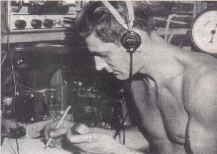 |
| Danny on the YASME - courtesy: www.gm3itn.co.uk |
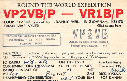 |
| Original YASME QSL - courtesy: http://hamgallery.com/ |
His exploits were regularly published in CQ magazine at the time and always made for exciting reading as Danny would eventually wreck three YASMES over the years! His adventures laid the groundwork for future island-hopping DX operations such as those undertaken by Gus Browning (W4BPD), Don Miller (W9WNV) and all that followed ... I'm sure they would all have enjoyed working the HAKUNA MATATA as well!
A 630m Maritime Adventure
|
| HAKUNA MATATA |
Crewed by Mark (VA7MM) and YL May (VE7MAY), Toby (VE7CNF) and XYL Nancy, the 31' Benateu recently completed a 14-day circumnavigation of Georgia Strait's Gulf Islands. This is a yearly adventure that has been successfully completed for the past few summers and looks as though it may now be an annual tradition.
Normally, the crew kept up regular radio contact on HF as well as on VHF when possible but this year saw a major departure.
In previous summers, near the end of the voyage, the crew has always visited us here on Mayne Island for an afternoon of vittles and libation before heading for home. There is always a good amount of time spent recalling the past-year's radio activities, winter projects and reminiscence of the 'good old days'. Last year, just as the party was ending, I jokingly suggested that 'next year', it would be cool to work them from the boat on 630m.
Although there was no immediate commitment, I knew that the seed had been planted, and with three of the four crew being engineers, I suspected it might be hard for them to resist, and ... just before departure, the local bunch of 630m ops were put on alert to be watching for CF7MM/mm on 475 kHz CW as they would be attempting to work us from three different overnight anchorages during their summer voyage!
Evidently Toby had been working quietly during the winter to make this become a reality. Here are some pictures of the system along with Toby's (the system's builder) comments.
|
| Variometer and matching transformer |
|
| Wire vertical and loading coil |
|
| Toby (VE7CNF) working the pileups! |
|
| Tuneup |
|
| The route, heading north from Vancouver |
Some of the contacts are shown below. Note the transceiver is not really on 160m ... it's just the i.f. for my 630m transverter!
I was impressed with the strength of ground wave signals given the low transmitter powers and EIRP's well below 5W. Received signals ranged from S1 to S9+10dB and copy was easy for all QSOs. QSO distances ranged from 10 to 142 km. We had low receive noise levels in all locations, with Silva Bay being a little noisier than the others due to many nearby boats and some shore power lines.
We tried disconnecting the gunnel ground wires and leaving only the keel, and found that the antenna capacitance and resistance did not change. When we disconnected the keel and left only the gunnel wires, the antenna capacitance dropped to about 87pF and antenna resistance dropped by a few ohms. It appears that the keel provided most of our ground coupling to sea water and it would have been a sufficient ground on its own.
More details of Toby's 630m transverter as well as a practical 630m antenna tune-up procedure can be found on his website here.
All-in-all, I think the 630m operation was a great success and very likely the first-ever 630m marine mobile operation on that band, as I don't recall this happening anywhere else over the years. It was also a great way to pay homage to the band's original maritime heritage where its quality groundwave and skywave capabilities were used to advantage for so many decades safeguarding mariners worldwide.
Maritime mobile operation on the amateur bands has some great history behind it, including the yacht YASME. In the mid-50's, Danny Weil was the first ever amateur to undertake DX'pedition style operations via sailboat, as he visited numerous rare islands in the Caribbean and South Pacific.
|
| Danny on the YASME - courtesy: www.gm3itn.co.uk |
|
| Original YASME QSL - courtesy: http://hamgallery.com/ |
His exploits were regularly published in CQ magazine at the time and always made for exciting reading as Danny would eventually wreck three YASMES over the years! His adventures laid the groundwork for future island-hopping DX operations such as those undertaken by Gus Browning (W4BPD), Don Miller (W9WNV) and all that followed ... I'm sure they would all have enjoyed working the HAKUNA MATATA as well!
LF / MF News From Monitor Sensors

A note from Roger, VK4YB of Monitor Sensors, reports some interesting news.
You might recall that his company manufactures a very versatile and well-engineered 630m transverter which was used at both ends of our two 630m JT9 contacts last year during the fall equinox propagation peak between North America and down-under.
Roger now reports that Monitor Sensors will be producing a new 2200m transverter, with all of the bells and whistles found on the 630m unit which has proven to be a real workhorse.
Monitor Sensors 2200m Transverter
The Monitor Sensors TVTR2 2200m Transverter enables any Amateur Radio Station, equipped with a conventional HF transceiver, immediate, all mode, access to the new 135.7-137.8 kHz, 2200m band.
The receiver design incorporates a 7pole Chebyshev filter, 3kHz wide roofing filter and a 5 pole Chebyshev filter in cascade before the double balanced, commutating mixer, fed by an ultra stable, temperature compensated, extremely low phase noise, MEMS local oscillator. The mixer is followed by a Chebychev band pass filter into an ultra linear, low noise, current feedback, IF amplifier. The receiver noise floor, in a 500Hz bandwidth, is -125 dBm and yet the onset of compression is not reached until +11dBm. A front end 20dB attenuator can be switched in for even higher signal handling. Overall receiver gain is set to +6dB, or -14dBm with attenuator in.
The transmitter input circuit incorporates a 0-14 dB switched step attenuator to prevent over driving. The same mixer and local oscillator are used on the transmit side. The PA uses 6 rugged lateral FETs in class AB push-pull to easily achieve the 50 watts rated output. Lateral FETs are inherently linear and thermally stable. The transmitter can be run at full power, indefinitely, into a dead short or open circuit without any danger of damaging the FETs. Transmit-receive switching is automatic with user selectable VOX delay. Alternatively the PTT line may be used.
The transverter employs extensive and accurate metering. Power input and output, SWR, Frequency, Attenuation in use, Temperature, Supply Voltage, Current and Resistance are displayed.
Transmission is inhibited if carrier frequencies outside the 135.7-137.8 kHz band are detected. A tuning screen may be selected which displays SWR in digital and graphical form for easy antenna adjustment. The menu system is self explanatory and users report no manual is needed, although one is supplied. A USB socket is provided for future code upgrades (free of charge) from the Monitor Sensors web site.
The transverter has been designed for the best possible protection against accidental mishaps. It will survive reverse polarity supply and the injection of 100 watts of HF into any of its ports whether in transmit or receive mode. If supply current exceeds 25 Amps, the supply is cut in 3 microseconds. This electronic breaker can be reset by simply switching off and on again. The transmitter will shut down in the unlikely event that the internal heat sink reaches 90°C. The cooling fan is under the proportional control of the microcomputer and begins operation above 35°C. Any unusual operation will cause the screen to turn red and an appropriate warning will be displayed.
TVTR2 Specifications
RF frequency range 135.7 to 137.8 kHz
IF frequency range 1805.7 to 1807.8 kHz (others available in the 160m band)
Transmission modes CW, SSB, WSPR, and all other data modes
Output Power 50 Watts Continuous, 100% duty cycle @13.8V supply
Input and Output Impedance 50 Ohms
Supply voltage 13.8 VDC @ 15 Amps nominal, 10-16 VDC operational
Rx noise floor -125 dBm (500 Hz bandwidth)
Rx 3dB compression point +15 dBm (Rx attenuator out)
Rx IF rejection better than 75dB
Rx conversion gain +6dB nominal
Roofing filter in-band ripple +/- 0.5dB
Tx 3rd order IMD -33 dB below PEP, typical at 50W output
Tx 5th order IMD -45dB below PEP, typical at 50W output
Tx harmonics and spurii All better than -50dB
Tx conversion gain +10dB nominal
Power input connector 2 * Anderson Power Poles (one Power cable supplied)
RF connectors 3 * SO239 (one PL259 to PL259 cable supplied)
PTT connectors 2 * RCA (one RCA to RCA cable supplied)
USB connector Micro B USB, (matching cable supplied)
Dimensions 12½ * 4¼ * 3 inches, 320 * 120 * 76 mm
Weight 3.4 lbs, 1.6 kg
In addition to the transverters, Monitor Sensors will also be manufacturing solid state amplifiers for both the 2200m and 630m bands with power levels at around the 450W output level. Like the transverters, these will be 'linear' devices as well. It is possible that a duo-band amplifier will also eventually be produced.
It will be interesting to see if any other new gear becomes commercially available from other manufacturers once the LF / MF ham bands are introduced in the U.S.A. , something that is expected to happen fairly soon.
LF / MF News From Monitor Sensors
A note from Roger, VK4YB of Monitor Sensors, reports some interesting news.
You might recall that his company manufactures a very versatile and well-engineered 630m transverter which was used at both ends of our two 630m JT9 contacts last year during the fall equinox propagation peak between North America and down-under.
Roger now reports that Monitor Sensors will be producing a new 2200m transverter, with all of the bells and whistles found on the 630m unit which has proven to be a real workhorse.
Monitor Sensors 2200m Transverter
The Monitor Sensors TVTR2 2200m Transverter enables any Amateur Radio Station, equipped with a conventional HF transceiver, immediate, all mode, access to the new 135.7-137.8 kHz, 2200m band.
The receiver design incorporates a 7pole Chebyshev filter, 3kHz wide roofing filter and a 5 pole Chebyshev filter in cascade before the double balanced, commutating mixer, fed by an ultra stable, temperature compensated, extremely low phase noise, MEMS local oscillator. The mixer is followed by a Chebychev band pass filter into an ultra linear, low noise, current feedback, IF amplifier. The receiver noise floor, in a 500Hz bandwidth, is -125 dBm and yet the onset of compression is not reached until +11dBm. A front end 20dB attenuator can be switched in for even higher signal handling. Overall receiver gain is set to +6dB, or -14dBm with attenuator in.
The transmitter input circuit incorporates a 0-14 dB switched step attenuator to prevent over driving. The same mixer and local oscillator are used on the transmit side. The PA uses 6 rugged lateral FETs in class AB push-pull to easily achieve the 50 watts rated output. Lateral FETs are inherently linear and thermally stable. The transmitter can be run at full power, indefinitely, into a dead short or open circuit without any danger of damaging the FETs. Transmit-receive switching is automatic with user selectable VOX delay. Alternatively the PTT line may be used.
The transverter employs extensive and accurate metering. Power input and output, SWR, Frequency, Attenuation in use, Temperature, Supply Voltage, Current and Resistance are displayed.
Transmission is inhibited if carrier frequencies outside the 135.7-137.8 kHz band are detected. A tuning screen may be selected which displays SWR in digital and graphical form for easy antenna adjustment. The menu system is self explanatory and users report no manual is needed, although one is supplied. A USB socket is provided for future code upgrades (free of charge) from the Monitor Sensors web site.
The transverter has been designed for the best possible protection against accidental mishaps. It will survive reverse polarity supply and the injection of 100 watts of HF into any of its ports whether in transmit or receive mode. If supply current exceeds 25 Amps, the supply is cut in 3 microseconds. This electronic breaker can be reset by simply switching off and on again. The transmitter will shut down in the unlikely event that the internal heat sink reaches 90°C. The cooling fan is under the proportional control of the microcomputer and begins operation above 35°C. Any unusual operation will cause the screen to turn red and an appropriate warning will be displayed.
TVTR2 Specifications
RF frequency range 135.7 to 137.8 kHz
IF frequency range 1805.7 to 1807.8 kHz (others available in the 160m band)
Transmission modes CW, SSB, WSPR, and all other data modes
Output Power 50 Watts Continuous, 100% duty cycle @13.8V supply
Input and Output Impedance 50 Ohms
Supply voltage 13.8 VDC @ 15 Amps nominal, 10-16 VDC operational
Rx noise floor -125 dBm (500 Hz bandwidth)
Rx 3dB compression point +15 dBm (Rx attenuator out)
Rx IF rejection better than 75dB
Rx conversion gain +6dB nominal
Roofing filter in-band ripple +/- 0.5dB
Tx 3rd order IMD -33 dB below PEP, typical at 50W output
Tx 5th order IMD -45dB below PEP, typical at 50W output
Tx harmonics and spurii All better than -50dB
Tx conversion gain +10dB nominal
Power input connector 2 * Anderson Power Poles (one Power cable supplied)
RF connectors 3 * SO239 (one PL259 to PL259 cable supplied)
PTT connectors 2 * RCA (one RCA to RCA cable supplied)
USB connector Micro B USB, (matching cable supplied)
Dimensions 12½ * 4¼ * 3 inches, 320 * 120 * 76 mm
Weight 3.4 lbs, 1.6 kg
In addition to the transverters, Monitor Sensors will also be manufacturing solid state amplifiers for both the 2200m and 630m bands with power levels at around the 450W output level. Like the transverters, these will be 'linear' devices as well. It is possible that a duo-band amplifier will also eventually be produced.
It will be interesting to see if any other new gear becomes commercially available from other manufacturers once the LF / MF ham bands are introduced in the U.S.A. , something that is expected to happen fairly soon.
LF / MF Antenna Planning
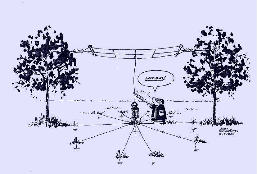 |
| courtesy: Chuck Roblin |
For U.S. amateurs, the 2200 and 630m bands will soon be a reality and I have no doubt that there will be an accompanying surge in interest among large numbers of homebrewers and low band diehards.
It should be an exciting time as new stations gradually start to populate the band from coast to coast.
High on the 'to do' list will be the planning and building (or modifying) of a suitable antenna system for the band(s) of choice. For most, this will be new territory, but the reality is that there has been a long tradition of operation in the LF and MF bands in the U.S. for many years ... all under the Part 15 'Lowfer' and 'Medfer' service.
Although activity in this category has fallen off over the years due to the availability of the much less-restrictive Part 5 experimental licences, there is still a great legacy of literature and information left behind that is every bit as useful today as it was back in the golden years of Lowfer operations.
Here is one such document from Stephen McGreevy's Natural ELF-VLF Radio website that many newcomers to these bands may find very helpful as it covers a wide variety of LF antenna-related basics in a down-to-earth manner.
An even more detailed treatise on virtually all aspects of LF and MF antenna topics is that found on Rik, ON7YD's website. His antenna pages can be found here. Although originally developed for the 2200m band, the principles are equally applicable to 630m as well.
Hopefully both of these sources will help you decide how to get a working antenna system up and running on the new bands. And as always, much help is available via the Internet on the Lowfer Reflector, the RSGB LF reflector or on the 600MRG Reflector.


