Posts Tagged ‘630m’
 Recent 630m Fun!
 |
The first was Frank, K6FOD, in South Pasadena, to the north-east of Los Angeles. Now if Frank can have success on 630m in this densely populated location, then most amateurs should be able to have fun on the 630m band!


Frank is running about 200W output into a short inverted-L. Up until recently, his antenna was a large wire loop pointing east-west with which he had a lot of success working stations towards the east. He and I had several skeds while he was using the loop but since I was directly in the null of the loop, I was never able to detect a trace of his signal, nor was he able to hear me! The break through came when the vertical was erected ... but I'll let Frank tell more of the story ...
As a long-time shortwave listener I had always been very curious about the realm below the AM broadcast band, so not too long after I got my ham license in 2018 I started working on a 630m rig.
Most ops on that band use inverted-L antennas, but they are highly dependent on a robust system of ground radials. At my location, there just isn’t enough open ground to lay out an extensive radial network. This seemed like a show-stopper.
However, John Langridge KB5NJD, who was writing the MF/LF column for CQ magazine, suggested that I try a vertical loop tuned by a vacuum variable capacitor, which does not use a ground connection at the feed point. He mentioned that this was being used at the time by Ben Gelb N1VF. Between Ben and John, they helped out greatly on getting it going. Mine ended up with a circumference of about 100 feet.
By adding a 630m class D amp to my K3S, which has an internal 630m transverter, I was able to get on the air with digital modes, which at the time were JT9 for two-way QSOs and WSPR for beacon modes. The winter of 2019-2020, I worked a dozen ops in six states, the most distant being South Dakota. My WSPR signal was heard from Hawaii to the Cayman Islands.
Due to their size compared with the wavelength of the 630m band, loop antennas like the one I built are notoriously inefficient. Based on measuring RF amperage to the antenna, I calculated that it was sending only 47 milliwatts into the atmosphere. On the other hand, the winter of 2019-2020 was near a solar minimum, the point in the 11-year solar cycle when conditions are best for the low bands. And there was also a lot of activity on 630m that year because it was a fairly newly approved band and was attracting a lot of experimenters.
One downside of the vertical loops is that they are fairly directional, with a deep null off their sides. Because mine pointed east-west, it was exceptionally difficult to hear or be heard by stations due north.
After that experience, other parts of life got in the way, and I didn’t get back onto the 630m band until the winter of 2024-25. That winter, I used the same rig and vertical loop antenna as before, and worked eight ops in six states and Mexico.
But due north was still unreachable. Steve VE7SL and I gave it a good try, but neither of us could hear the other. So in the fall of 2025, despite my limited ability to lay out ground radials, I thought I’d give an inverted-L antenna a try. John KB5NJD again provided great guidance, and Steve VE7SL also lent very useful ideas.
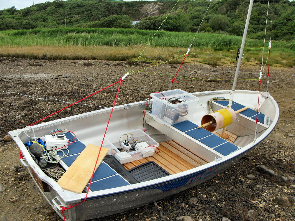
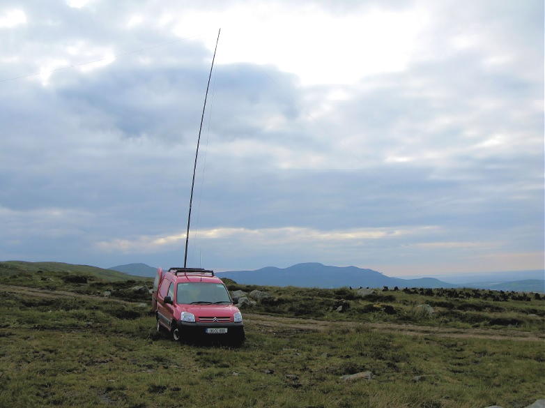
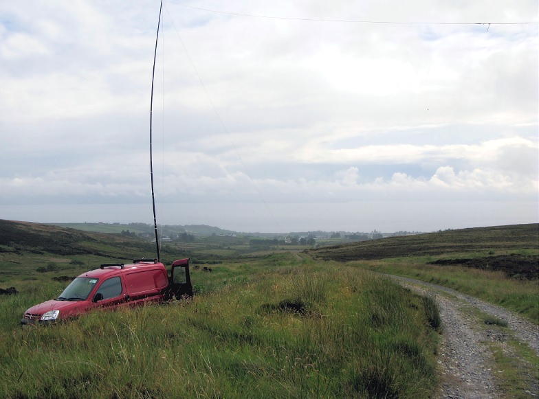
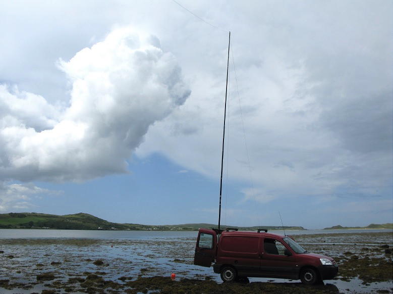
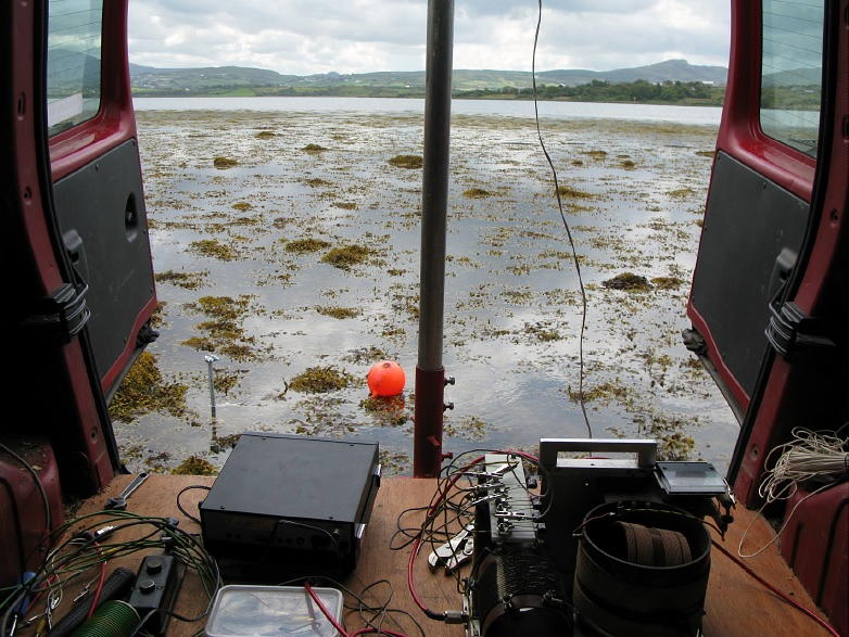
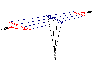
At my location, going super tall wasn’t going to be feasible, so I ended up with a lightweight aluminum mast of 36 feet height. Because of my lot’s dimensions, instead of having one top wire to form the inverted L, I used two top wires in opposite directions, each 50 feet long — making what some call a “Tee Antenna.”
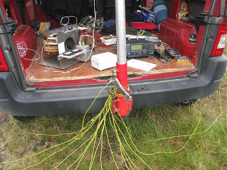
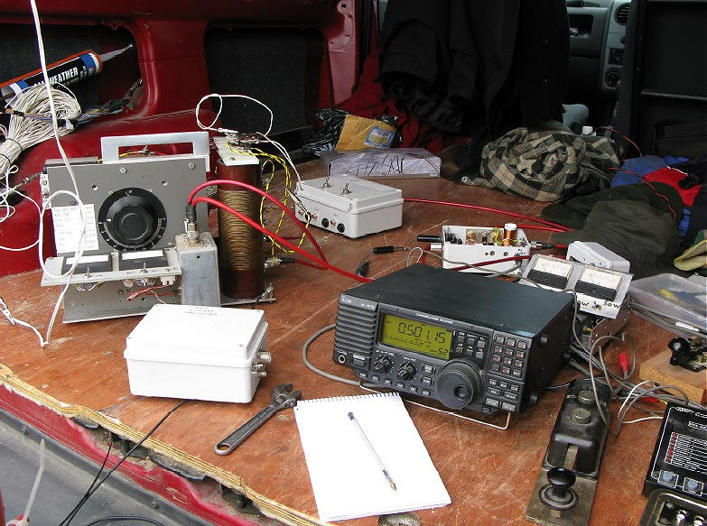
Like inverted-L’s, its small size compared to the 630m wavelength meant it would require a substantial loading coil. I made this using a popular approach of a large coil wrapped around a 5-gallon plastic bucket, with a small coil inside it on a turnable rod, which allowed the total inductance to be adjusted. The big coil also had tap points. An impedance matching transformer was wrapped on a stack of four FT240-77 toroids. For a rig I decided to try an SDR transceiver which opened up possibilities of CW and SSB voice in addition to digital modes.
For the ground system, I tried laying out a set of 18 radial wires ranging in length from about 10 to 80 feet due to the site’s available space. My antenna analyzer indicated that R_feed was around 62 ohms. Measurement with an RF ammeter showed that about 1.25 watt was now getting into the atmosphere (this being the effective isotropic radiated power, or EIRP). The FCC limits 630m ham transmission to 5 watts EIRP, which means I have ample room for improvement, hopefully by adding however many more ground radial wires I can squeeze into my limited space.
After six weeks of operating in January-February 2026, this season I’ve worked six ops so far in three states and British Columbia. Hoping to add more if I can improve the antenna’s ground network.
When not in use for 630m, I’ve also attached the Tee Antenna to a multicoupler serving a small “skimmer farm” of SDRs that monitor FT8, CW and WSPR signals on ham bands from 630 to 10 meters. In addition, I’ve used it with an SDR for receive-only DX listening for non-directional beacons (NDBs), airport beacons that transmit below the AM broadcast band in North America. So far the Tee Antenna seems more sensitive than a number of other antenna designs I’ve tried for NDB listening. I also plan to use a remote tuner placed at the antenna to allow it to be used for CW, FT8 and voice QSOs on the HF bands.
 |
| K6FOD - 36' 'T' for 630m |
 |
| Loading coil / variometer |
 |
| Antenna impedance matching transformer |


The Joys Of ERP
The following blog was originally published four years ago and with the ever-growing number of new 630m stations, some may find the information helpful.
****************************************
Amateurs and and U.S. experimental licence holders operating on the LF and MF bands, are limited in the amount of power they are legally able to run. Unlike the HF bands, where maximum power limits are expressed in either DC power input or PEP output, LF and MF operators are required to observe ERP or EIRP limitations. Canadians operating on 2200m are limited to 1W EIRP and to 5W EIRP on 630m.
Although this doesn't sound like much, mustering this amount of effective power can be quite a task on either band, especially on 2200m. This is due to the very poor efficiencies encountered when using antennas that are so small in size compared with what would be considered 'normal'. For example, a typical 1/4 wave vertical used on 40m is about 33' high and with a good radial system can achieve efficiencies in the 80% range, while the equivalent antenna for 2200m would be 550m or about 1800' high ... a little large for most suburban backyards!
The equivalent of a normal 2m 'rubber-ducky' antenna when built for 2200m would be over 600' tall, while one designed for 630m would be around 170' high! A 2" stub used on your 2m hand-held would be the same as a 56' vertical on 630m. Consequently, most LF / MF backyard antennas will realize efficiencies of less than 1% and likely, quite a bit less.
In order to reach the maximum radiated power levels allowed usually requires several hundreds of watts, especially on 2200m, where near kilowatt levels are needed. These small radiated power levels might seem discouraging but they don't account for radio's great equalizer ... propagation. More than anything else, RF loves to radiate, and at times, what can be achieved on these bands with such low effective radiated powers is stunning
It would seem that Industry Canada did us no favors when they stipulated LF / MF power levels to be measured in EIRP and not the, much easier to calculate, DC power input level ... or perhaps they did. I think that, unlike on HF, imposing EIRP rather than DC input power limits puts everyone on an even playing field. Amateurs with lots of real estate and room for a larger, more efficient LF antenna, will be required to run much less power to reach the allowable EIRP and 'stay legal', compared to someone with a small backyard in the suburbs ... the latter can legally generate the higher level of DC input power required to reach the EIRP limits since their smaller antenna is operating at less efficiency. However, determining EIRP is not as cut and dried as measuring input power.
With some fairly sophisticated (ie. expensive) field strength measuring equipment, not typically found in amateur radio operations, ERP / EIRP can be readily determined. This means that for most amateurs, alternate methods must be used.
Neil, WØYSE in Vancouver, Washington, who runs an experimental 630m station under the call of WG2XSV, has produced an excellent treatise on calculating your station's EIRP level, providing a step-by-step procedure to follow.
In order to determine your ERP / EIRP, you must first determine your antenna's radiation resistance. Two methods of calculating the antenna's radiation resistance for both verticals and top-loaded verticals (inverted L's or T's) are demonstrated, using the physical size of the antenna in relation to the frequency of operation. Once this value is known, the antenna current is measured while transmitting. These two values allow the Total Radiated Power (TRP) to be calculated. The TRP is then multiplied by 3 to yield the EIRP or by 1.82 for ERP. Roughly speaking, 5W EIRP is the equivalent of 3W ERP. Thanks to Neil for this helpful resource.
An alternate method of roughly determining ERP / EIRP values is an interesting new online 'antenna simulator' at the 472kHz.org site. Using known physical sizes along with your ground quality description, the calculator will indicate what total power output is required to produce various levels of ERP and EIRP as well as expected antenna currents, at 472kHz. It's a good starting point if you are either planning a new antenna system or perhaps, repurposing an HF antenna such as an 80m inverted-L or an HF center-fed dipole for use on 630m.
Neil has also sent the following comments that will be of interest to those planning a sloping-wire tophat:
Hi Steve,
I'm sure there will be a lot more information and discussion about this topic once the LF and MF bands are released in the U.S.A. but in the meantime, calculating your ERP / EIRP levels is not as hard as it might initially seem ... and is likely accurate enough for most agencies overseeing amateur radio activities.
630m … The New ‘Magic Band’?
The 'magic band' has always been associated with 50 MHz and its amazing propagation ... usually unpredictable and often without logical explanation. This past summer saw an explosion of digital FT8 activity on 6m which has, for me (and for others I suspect), eliminated almost all of the enjoyment I have found every year on this band.
With so much of the previous CW and phone activity now gone to FT8, the 'feel' of the band is just not what it once was. What I find puzzling is that so many have embraced this weak signal mode yet most of the two-way QSOs seem to be made between stations that can easily hear each other ... often at the very strong levels produced by 6m sporadic-E!
With FT8's inability to chat about antennas, rigs, propagation, locations or simply to exchange names, for me the magic has gone. Being able to hear signals build, fade up and down, or to experience the sudden arrival of bone-crushing signals from the east coast where none had existed moments earlier, is all part of what attracted me to 6m decades ago. I spent only a few hours on the band last summer, working a number of JA stations on FT8. No particular sense of satisfaction was garnered ... working a JA opening on CW is just way more exciting!
For many, the arrival of FT8 to the magic band has opened a whole new world and from seeing so many unfamiliar call signs on 6m this summer, it seems that FT8 has brought a lot of newcomers to the band. Unlike the JAs' worked every summer on CW, almost all of the FT8 JAs' sent their QSL immediately, with almost all excitingly indicating "1st VE" ... so this has to be a good thing! I suspect, that unless the level of conventional-mode activity returns to previous levels on 6m (highly unlikely), my interest in 50MHz will slowly wane or vanish altogether ... but thankfully, there's still magic to be found elsewhere on the ham bands!
As solar Cycle 24 draws down into its final months, the deep lows that were experienced at the end of Cycle 23 are starting to develop once again. For the past few weeks, propagation below the broadcast band has been the best it has been since the previous solar quieting.
Being just below the bottom edge of the broadcast band, 630m (472-479 kHz) has seen some of the benefits of the recent round of stagnant geomagnetic activity.
While some transcontinental QSOs are regularly being made on CW, most contacts are being completed using the weak signal JT9 QSO mode. Contacts can often be completed just as the sun begins to set and staying up into the wee hours to catch east coast DX is not a requirement. Over the past few weeks my 'states worked' total has climbed to 30 and with a couple of holdouts, the QSLs have been steadily arriving.
 |
| My 630m states worked, shown in red. Map courtesy: https://mapchart.net/ |
Last month's arrivals, in spite of the Canada Post delivery disruptions, are shown below.

The recent great propagation on 630m is well-demonstrated by last Saturday night's activity. For the previous two evenings, my JT9 CQ's (as well as QSOs) were being decoded for hours at a time by Rolf, LA2XPA in Norway. He was also hearing Larry, W7IUV, located a few hundred miles to my southwest, on the other side of the Cascade mountains in Washington state. Both of our signals would fade and trade places in Norway but often reaching audible CW levels! The problem was that neither myself or Larry could see any of Rolf's replies to us ... disappointing to us and frustrating for Rolf.
After an hour of trying, I asked Rolf (via the ON4KST LF chat page) what he was using for a receive antenna. It turned out that his secret weapon was a 1000' beverage pointed this way ... no wonder he was hearing so well. Larry, who was using a shorter, easterly pointing BOG (Beverage On Ground) for 630m receive, commented that he also had a 1000' beverage pointed toward Europe but it was optimized for 160m and doubted that it would work on 630. Just to make sure, he plugged it into a second receiver and soon indicated that he 'might' have seen a weak JT9 trace on the waterfall, close to Rolf's frequency.
One minute later Larry's comment was just "wow!" and the following minute he explained what had occurred. It seems that the 'possible weak trace' had suddenly skyrocketed to a -16db signal ... right at the edge of audibility! Larry and Rolf quickly exchanged signal reports and "RRs" as the first Europe-West Coast 630m QSO went into the history books ... 'wow' indeed!
Rolf reported that at his end, Larry's already good signal suddenly shot up to -5db, an easily copied CW level, before fading away for the night. Larry was pretty shocked at how quickly this strong short enhancement had occurred and we all hoped that the oft observed 'spotlight' propagation seen on 630 would move further west to VE7 ... but for now, it was not to be.
Earlier in the evening I had commented to Larry about some previous quirky 630m propagation and had suggested to him that it was probably just due to "the magic of radio" ... to which he politely dismissed with "sorry no magic, just hard work and dumb luck". Looks like he was right on both accounts, but after Saturday's excitement I think he may now believe in a little magic as well!
The 630m Portable Adventures of EIØCF
In the years before amateurs in the UK had access to the 630m band as we know it today (472-479kHz), hams there could apply for a 'special research permit' allowing them to operate between 501 and 504kHz.
One of the first and most active stations was operated by Finbar O'Connor, EIØCF, located in the most northern part of Ireland, near Malin Head. In the early days, Finbar might as well have been AC4YN in Lhasa, Tibet, as a 630m or a 2200m QSO with EIØCF was a much prized DX trophy and a genuine 'right of passage' for many little backyard LF and MF stations throughout Europe.
Nowadays, 630m activity in Europe is not as robust as it once was but Finbar is still active on MF from his modest station. He reports being copied in North America on several occasions. Although mainly active in the WSPR mode, Finbar is now considering the two-way JT9 weak signal QSO mode and may hopefully once again, tease east coast North American MF operators with a new rare entity from his seaside location.
 |
| Finbar's WSPRlite setup for 630m |
 |
| EI0CF/marine on 630m! |
What follows is a delightful adventure, in Finbar's own words, describing some of his field trips back in the 500kHz experimental days ... perhaps it will inspire some North American portable work or provide ideas for an emergency prep 630m grab-and-go kit, or just get you excited about our newest amateur allocation.
******************
Operating Portable on 501 - 504 khz Medium Wave
Operations on the north flank of Slieve Snacht Inishowen Peninsula.
In June 2009 Ireland joined a growing number of countries permitted to operate on a small portion of the medium wave band, just below the commercial broadcast segment, in the range 501 - 504 khz. Several stations were granted permission and operations commenced. As has been documented elsewhere many stations have been worked, both in band and cross band, at home and abroad, ranging from Continental Europe, across the Atlantic to the USA and Canada, down to the southern end of Ukraine and finally up to Iceland, Norway, Sweden, Finland and also being heard in Moscow.
A notable feature of this band is the steady reliable nature of groundwave coverage and with this in mind I recently availed of the facility whereby portable operations can take place. Comreg, together with the IRTS and the individual involved, require that each event is applied for, giving relevant dates, location, contact details, hours of operation and the power of the transmitter being used.
In the period leading up to all this it was necessary to build and test a viable portable station based on the use of my Berlingo van. A 30' part of a 40' Spiderbeam fibreglass pole was used with a simple round wooden peg to secure the 'Tee' wire antenna, which was fabricated from twin twisted multistrand speaker wire. The vertical used both, while the rest was pulled apart to form the two horizontal legs.
A 100 metre roll of 1.5 mm insulated earthing wire was cut into 16 lengths to provide radial wires, with lugs soldered to one end and a bonding bolt used to secure a single point for the radial kit. The far ends formed a small loop which was sealed and secured with insulating tape. The loop provided an eye for a small L shaped stiff wire, fashioned from discarded coat hangers, an ideal and cheap way to hold the ends of the radial wires in place in the ground.
To secure the antenna support to the van, I refer you to the excellent idea described by John EI7BA, on his web page, for a ball hitch connection:
http://www.qsl.net/ei7ba/a_ball_hitch_mobile_mount.htm
Using this superb idea, I got the welder out and made one for myself. It worked perfectly.
I now had the support and wire antenna, with a ballpark figure for what might resonate, along with the radial kit. I next needed a dedicated antenna tuning unit. An old variometer and two extra fixed multitap coils were selected. A home made 1 amp ammeter and SWR twin meter unit completed the fit-out. These were all assembled on a base with a handle on the top, making it easy to move around whilst out and about.
The main antenna for 500kHz was disconnected and left floating and the van set up with all this gear, but no transmitter. Instead, my little antenna bridge running off a 9-volt battery provided the necessary signal to start testing for basic resonance.
Whether from sheer good luck or some sub-conscious input, resonance fell within the range of the variometer with only one of the two extra coils in circuit. The relative height and length also play a part in the range of resonance secured. Matching to 50 ohms was then optimized by selecting 4700 pf Mica capacitors using Croc Clip links. The available value ranged from 1 nF to 14 nF.
I have a selection of 500khz transmitters, two of which are to the design of Roger, GW3UEP, who lives 10 miles inland from the coast, in south Wales. His 500khz web site is well worth checking out, containing plans for versions of his 500khz transmitters, test equipment pictures and recordings of 500khz activities.
http://www.gw3uep.ukfsn.org/
One of these was used to put some RF into this first portable style installation, and by arrangement, Roger listened and heard my signal. We delightedly completed a short contact, with my transmitter running just 10 watts.Things were looking good.
One of the very valuable things about portable operations stems from the need to bring together several elements to secure a working radio station, without the usual backup we enjoy from home. Planning is essential. Doing a dry run, i.e. actually physically building the intended station then notating all the gear required and making a list as well as providing backup items, particularly those that which if broken or lost, would render the whole radio station non-viable. This also extends to the operator of the equipment. Will they be warm or cool enough, have shade, food, water and enough needed rest? Always be prepared to abandon the project if safety is compromised, for whatever reason.
Now that I had a viable portable station for 500kHz working, it was time to head off and test both the equipment and myself in the real world, but without any live transmissions taking place.
Several sites were chosen and tested, with particular emphasis placed on remoteness, i.e. high up on mountains or near the sea. All sites worked very well, but those by the sea proved really excellent. Reception of NDB’s (Non Directional Beacons) provided a ready supply of medium to low frequency signals for range testing. I was now itching to “ have a go “ out in the wilds, on 500kHz! Using the method required by Comreg, an application was made for several sites, on specific days.
In early June I loaded up the van with all the gear and headed off for the mountain above Redcastle, County Donegal. Using a narrow track and climbing higher, to about 270 meters, a place was found leading to an old quarry. Typically, it had started to rain. By the time I had erected the support pole, pulled out and secured the top hat wires using light nylon line and deployed the radial wires around and below the vertical drop wire, my trouser ends were very wet!
Plugging in the 12-volt supply, the receiver was very quickly perked up, using the variometer. The Morse key connected to the QTX transmitter and the transmit / receiver switch flicked over. Time to get some RF flowing in the antenna. Sure enough, on key down, the antenna current meter shot right up to 400 mA, but the SWR match was not exactly perfect. Time to work those Croc Clips and start selecting shunt capacitors to find the perfect match. Soon I had that sorted to my satisfaction, with antenna current now up to 550 mA. A quick return to receive showed that Roger, GW3UEP was already tuned up on frequency.
"..... GW3UEP DE EIØCF/P HW K"
He came back straight away! Oh joy, we were on the air on 500, in a remote mountain area, the top of my antenna almost tipping the clouds as they swept past. I was open to the elements, standing at the back door of the van with the tips of my fingers reaching for the knob of my very favourite old Amplidan morse key, snug beside the other bits and pieces of equipment on the van floor!
My logbook, with its pages flapping back and forward in the wind, soon had the first 500kHz portable contact documented. A full hour later, solid steady signals continued at a distance of 250 miles. Proving just how good groundwave signals can be, I terminated communications from the remote portable location, happy with the results. Within 12 minutes I had dismantled the station and was on my way to Moville, along with a strong cup of coffee at the café on the town's main street.
Several other portable operations have since taken place. A number have also occurred at my home location. We live right beside the sea; high tides lap up on to the salt marsh, which is part of the property.
Driving a single earth rod into the sea shore to a depth of 1 metre, with no radials and just a single wire between the rod and the ATU earth, the 1 amp RF meter had its meter needle slamming against the end stop. Lots of antenna current for 15 watts transmitter output power. Those same 15 watts only providing, at best, 550 mA, whilst up on the mountain sites.
Finally, it was thought productive to try a kite-supported antenna from the seashore portable set up. Winds on the day selected seemed strong enough to enable my Delta shape kite to head aloft with a flying line and antenna wire attached. The Berlingo van was driven down on shore, everything connected and tuned up. All was well, or was it?
The receiver now seemed quite dead with no band noise and no antenna current on transmit. Looking skywards I could see nothing. My eye followed the antenna wire heading for deeper water. Then I saw it. The kite had plunged into the sea! The following 30 minutes entailed untangling loads of seaweed with the line wrapped around rocks, barnacles and everything imaginable. What a mess! I almost gave up, but knew that Roger would be coming up on frequency, on sked, in about 15 minutes.
Eventually I managed to get the kite skywards again but by now the wind was acting more unpredictably. I established contact with Roger and he immediately gave me an S 7 report for my 15 watts. This equated to the report I would get from my main station antenna running 100 watts. My single ground rod and 150 feet of wire were doing the business.
We carried on our contact, but what remained became a battle of wits, with a kite constantly diving down and soaring up again. Several times the antenna wire was in part lying on the sea shore and antenna current way down to 200 mA or lower. My left hand was on the variometer tuning knob, tweaking the setting as best as possible, while pulling in the slack to keep the antenna wire off the ground. Feeding the wire out again to a misbehaving kite, I kept keying away with my right hand, keeping Roger updated so he could understand why my signal was changing both in pitch (sudden antenna mis-match conditions) and signal strength.
Luckily he was also making a recording, which proved later to be a fascinating record of a difficult portable antenna and station operation. It’s remarkable how tolerant, despite the wildly changing antenna conditions, the system actually was in practice. Communications were maintained despite all these negative factors and severely decreased radiated power at times.
Several other tests were conducted within these experiments which would have been almost impossible to conduct without the challenges thrown up by my portable operations. To my mind the 501 – 504khz band exhibits a distinct advantage for enhanced groundwave coverage over that available to higher frequencies.
Relatively simple equipment deployed in remote locations, with or without the availability of the power grid, would provide a solid backbone link or network in times of emergency. Transmitter power output was kept deliberately low to ensure that a higher ERP would not mask any possible weakness in the system. I am happy to conclude that Medium Frequency CW proved it’s worth once again.
Already I have further plans to test smaller, more compact portable antenna and earthing systems in more remote locations.
Finbar O’Connor EIØCF Malin, County Donegal.
630m – Winter One
The steady arrival of new stations on the band was exciting to see and the increase in activity made nightly band-checking mandatory in order to keep up with the new arrivals. Not totally unexpected, a high percentage of the new stations were located in the eastern part of the country where ham populations are higher, giving even more incentive to watch propagation trends for those 'special' nights to put some of the new arrivals in the log.
Over the winter DX season I worked 37 'new' U.S. stations in 23 different states. Of these 23 states, 11 were on CW while 12 were on JT9. Many of the JT9 contacts could have been made on CW at the time, had that been the operating mode chosen.
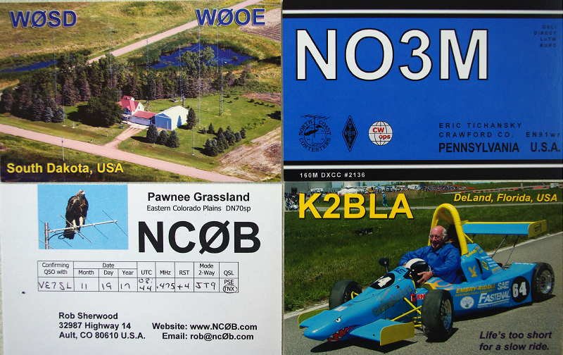
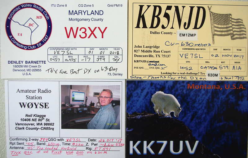
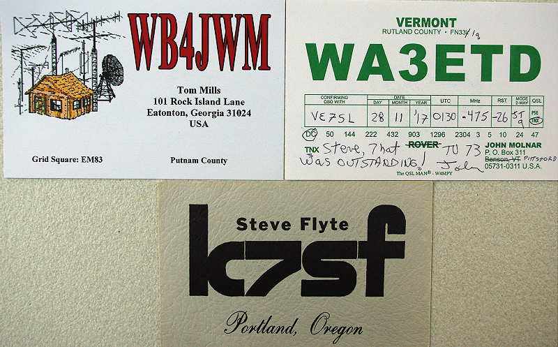
Hopefully the band will see an increase in CW activity next year as activity continues to grow. It is certainly much easier to get a capable CW signal on the air than a digital one and that is what many decided to do to get a quick start, while going the transverter route was the method chosen by most.
After being active all winter, the biggest surprise for me about 630m was just how little actual power is needed to exchange coast-to-coast signals, especially when using the weak-signal digital JT9 QSO mode.
Almost every new station that I worked was running less than 100 watts of total per output (TPO). A large number of these stations were in the 20 watt TPO range which I really found astounding, considering the relatively poor efficiencies of typical backyard antenna systems on this band. Propagation, always the great equalizer, was certainly playing a major role at times and watching conditions change from night to night was an education in itself.
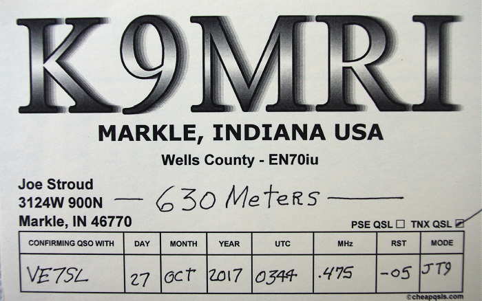 |
| K9MRI - 22W / 72' vertical wire / 140' tophat (72' x -140') |
 |
| K9FD/KH6 - 100W / 70' x 70' inverted-L |
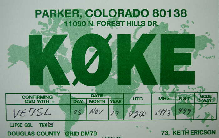 |
| K0KE (CW) - 75W / 70' x 50' inverted-L |
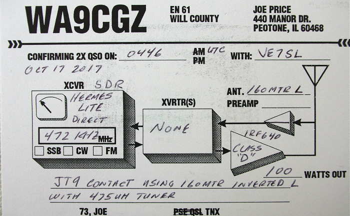 |
| WA9CGZ - 100W / base-loaded 160m inverted-L |
 |
| N1BUG - 20W / inverted-L |
 |
| KC3OL - 15W / base-loaded 'T' |
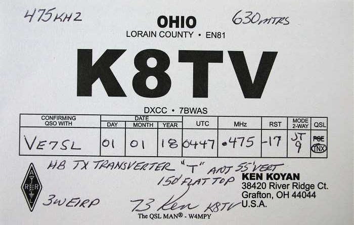 |
| K8TV - 3W eirp / 55' x 150' 'T' |
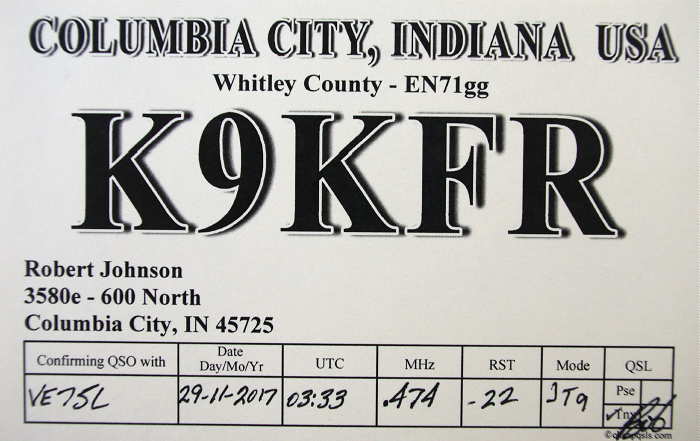 |
| K9KFR - 20W / 80' wire vertical |
 |
| KA7OEI (CW) - 25W / 200' circular loop at 30' |
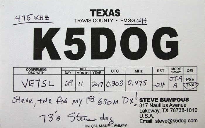 |
| K5DOG - 16W / 275' vertical loop |
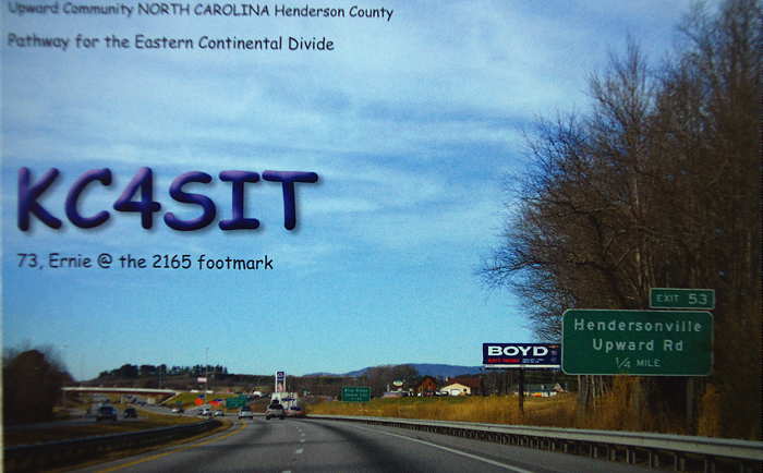 |
| KC4SIT - 60W / inverted-L |
Although Canada's west coast is now well-represented on 630m, it would be really great to see some interest and station building from provinces to the east ... VE6, VE5, VE4 ... The fast-approaching warmer weather should provide the ideal opportunity to get any needed antenna work squared away before the next DX season begins along with its anti-antenna building winter weather!
If you are one of many amateurs that may have been contemplating some 630m work but were discouraged about antenna sizes or having to generate gobs of power, hopefully the above information will encourage you to get on the band and join the fun.
You can find more information that may be helpful in your quest via the 630m links on the right side of my blog page or by clicking here.
The FA-VA4 Vector Antenna Analyzer (LF-100MHz)

For some time I had been considering the purchase of the MFJ259 antenna analyzer but after a little online sleuthing, came across this little beauty, the FA-VA4 Antenna Analyzer by Funk Amateur in Germany and available through their Box73 website here.
I liked the fact that the cost of the analyzer was about half that of anything else comparable ($140 US including shipping) and that it covered the new 2200 / 630m bands!
I think many amateurs planning on building a system for either of these new bands will find the very affordable FA-VA4 a handy piece of equipment when it comes to working on their LF / MF antenna since most available SWR meters do not cover these frequencies accurately.
Delivery time was fast and everything was very well packaged. The FA-VA4 comes in partial kit form and requires only a short amount of time to put together.
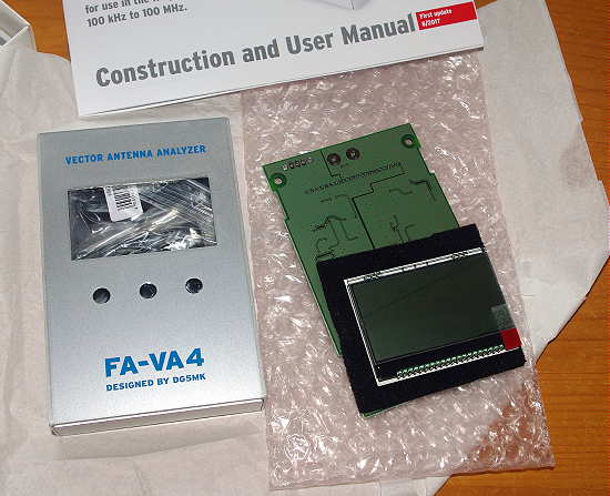
The necessary assembly consists of soldering pin strip connectors, switches, AA cell holders, and the BNC connector. All of the tricky SMD components have been pre-mounted ... total assembly time was less than 60 minutes and everything fired-up nicely, without problems, thanks to the well written instruction / user manual.

Included with the kit are three BNC connectors needed to calibrate the instrument for the highest accuracy. These consist of a 'Shorted' connector, an 'Open' connector and a 50 ohm 'Load' connector (SOL). A simple three-part calibration procedure for all frequencies takes about 15 minute to complete, while the instrument calibrates itself as it scans through all frequency ranges with each connector plugged into the output. Once this task is completed, the analyzer is ready for use.

If you're like me, I think the main use will be to check out and tweak some of your HF antennas using the SWR or Z sweep function. This allows you to set a desired 'center' frequency along with a + / - sweep range and have the display draw a nice plot of your system.
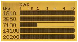
Had my 630m antenna not already been tuned and matched, I would have found the analyzer to be a great help but, thanks to my 'scopematch', that antenna has already been optimised.
All menu features and data entry is via three momentary-contact push switches. Although this might initially seem awkward, it is not, and operation is pretty intuitive.
The main modes of operation are:
Single Frequency SWR Measurement
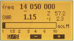 |
| courtesy: http://www.box73.com/product/5 |
Single Frequency Impedance Measurement
 |
| courtesy: http://www.box73.com/product/5 |
Single SWR Measurement Run
 |
| courtesy: http://www.box73.com/product/5 |
Single Run For Impedance Measurement (Resistance and Reactance)
 |
| courtesy: http://www.box73.com/product/5 |
SWR Measurement On Five Frequencies (5 Band Measurement)
 |
| courtesy: http://www.box73.com/product/5 |
As well, all of the above can be viewed in a continuous 'cycle' mode, as inputs are changed and all screens can be saved for future reference.
Additional capabilities include use in an HF Signal Generator Mode (~ 1V square wave @50 ohms), the ability to measure C and L at a given frequency, as a 'dip meter' and to measure cable resonances and determine lengths.
The complete manual may also be downloaded from their website here.
I will soon put all of my antennas to the test and see what work might need to be done to optimize them, particularly my HF half slopers, which, in spite of their great performance, have always proven a bit of a mystery when it comes to pruning them to resonance ... I rather suspect that the sloping wires are more of an impedance tuning stub than a radiator and that most radiation comes from the vertical support tower, not the sloping wire.
All-in-all, the FA-VA4 appears to offer very good value for the money and is a well built, quality test instrument. I think it will become a popular choice among hams, especially those on LF / MF. The only thing different that I would have liked, would be to have a UHF (SO 239) connector rather than a BNC on the output, since most amateurs are using these on their HF systems ... or, the inclusion of a BNC-to-UHF adapter.
If you already use this device, please feel free to add your comments below!
Getting Started On The New LF and MF Bands
 Finally the long wait is over! The LF 2200m band and the MF 630m band have finally arrived for amateurs in the USA! I'm sure most of you have read the fine print regarding deployment of the two bands, but if not, here is the ARRL's recent announcement.
It has been a very long wait for the FCC to implement these bands after they were approved for amateur use in 2007 and 2012 at the World Radiocommunication Conferences in Geneva. Canadian amateurs have had 630m since 2014 and 2200m since 2009 ... in the meantime, we have been anxiously awaiting the arrival of American amateurs to liven things up and to garner new interest in these bands.
Before operating on these bands, amateurs in the USA are required to register their intent via a simple web form found here on the Utilities Technology Council's website. Then follows a 30 day waiting period during which the UTC will check out your location to be sure that you are not located within 1km of any power lines that might be carrying LF or MF PLC (Power Line Carrier) control signals. If you hear nothing back from UTC within 30 days, you are good to go.
A positive outcome of registering via the UTC form is that there can be no PLC signals implemented on the lines near you at a later date! By registering your intended operating location(s), you are locking-in these spots for no further PLC development. If you have an EOC or Field Day site that you think you may want to operate from at some point, register these as well.
I think it is important that even if you do not intend to operate on either of these bands or perhaps a few years down the road, that you register as soon as possible ... the fewer PLC signals operating close to or within the amateur radio spectrum, the better, and this is one way of furthering that goal.
There has already been a vast amount of published information on both of these bands, describing transmitters, receiving systems and transmitting antennas so I won't go into much detail here regarding these topics ... and besides, it's always very interesting to search these things out yourself, learning as you go. Be assured that either of these bands will present interesting new challenges not encountered in typical HF operation, but all of the basic principles you are used to still apply ... it's just that things are much bigger down below the broadcast band!
Far and away, the best source of information for US amateurs can be found on John Langridge's (KB5NJD) NJDTechnolgies website. John has been operating on MF for several years already with an experimental licence (WG2XIQ) and is more than an expert on this topic.
His daily blog includes a detailed account of worldwide activity on 630m and makes for fascinating reading. His website provides all of the information and valuable links that you might need to plan your own LF or MF station. The information on his site, if printed out, would make a wonderful LF / MF Handbook!
My own blog and website also contain much helpful material, with a particular emphasis on Canadian activity on these bands. All of my blogspots dealing with 630m can be found here and contain enough bedtime reading to keep you busy for many nights.
If you are thinking of getting on either of these new bands, particularly 630m, here is a short Q & A that may help you through the initial planning stage of how to get started.
What modes are commonly used on these bands?
At present, due to the low level of two-way amateur radio activity, the WSPR mode has been dominant. This is a weak-signal 'beacon-only' mode so most two-way contacts take place either on CW or on the weak signal JT-9 mode. JT-9 has been specifically designed for HF and LF / MF weak signal two-way work and can dig as deep as -27db into the noise to provide a contact that could never be completed on other conventional modes such as CW.
With the influx of new activity on these bands, particularly on 630m, I expect that most two-way work will equal or surpass the amount of WSPR activity and that JT-9 and CW will do most of the heavy-lifting.
How far can I work on these bands?
Although the erp limits appear to be QRP-sized, this is somewhat misleading ... it is astonishing what can be done. Don't think that '5W eirp' means that you can only run a transmitter capable of generating 5W. Because antennas are so inefficient on these bands, it is often necessary to run several hundreds of watts in order to achieve the legal eirp limits. The bigger and more efficient your antenna, the lower the power needed becomes. On many nights, 5W eirp will get you clear across the country on MF.
However, if you build something for 630m that only produces 25W of power, you will still have the capability of working many stations in other states on most winter evenings or mornings, as propagation, the 'great equalizer', can be amazing at times.
Presently, most stations operating on WSPR will often be detected from one coast to the other and those with excellent locations near the coast will soon be working stations down under or in Europe, either on CW or on JT-9. If you can, design and build for the maximum eirp, 1W on 2200m and 5W on 630m.
What type of transmitter do I need?
If your interests are only in CW, then the sky is the limit when it comes to design. There are numerous simple solid state transmitter designs out there, using inexpensive FETs to generate power. I'm hoping, along with many others, that there will be a considerable amount of CW activity on 630m and even a simple 25-watter should provide you with lots of fun. There may also be some appetite for QRSS CW which can give the weak-signal digital modes a run for their money while still using a simple transmitter.
If you are interested in digital modes, such as WSPR or JT-9, the easiest way is through the use of a transverter to take care of converting your HF transceiver's capabilities to LF or HF. There are presently a few commercial transverter options available and can be found on the NJDTechnologies links page.
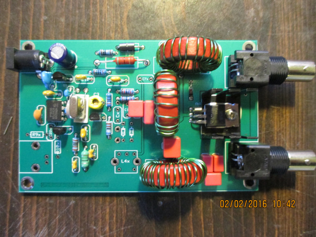
A good choice is the inexpensive 630m transverter produced by John Molnar, shown below and available both as a kit or prebuilt. It works well and is very popular.
 |
| 630m Transverter - John Molnar WA3ETD / WG2XKA |
 |
| G3XBM -630m Transverter |
If you want something in the 'Collins category', the tranverters (both 2200m and 630m models) produced by VK4YB's Monitor Sensors provide around 70W output and are incredibly well designed and built. I have been very happily employing a 630m model for well over a year now ... my review of the transverter can be found here.
 |
| VK4YB - 630m Transverter |
I would like to put on a beacon. What do you suggest?
The best and most informational type of beacon is a WSPR mode beacon. A WSPR beacon operator can always determine where his beacon is being heard, in real time, along with how well it is being heard, by watching the uploaded 'spots' of his beacon on the WSPRnet. You will have much better coverage with this weak-signal mode beacon compared to one on CW ... for every CW report received, you would likely get ten times or more that number on WSPR.
Although WSPR is a great mode for checking out propagation, it's very easy to get into the habit of nightly beaconing and not developing your station any further. If you do run a WSPR beacon, be sure to try some of the other two-way modes such as CW or JT9 and call CQ regularly ... ham radio is all about making two-way contacts!
I don't have enough property for the large antennas required, so I won't be able to use these bands.
Even if you are limited in space, you can still enjoy these bands. There are many examples of stations on small city or suburban-size lots that are consistently heard across North America on 630m. If you have the room for an 80m or 40m dipole or inverted-L, that will be enough space to work these bands. An inverted-L for example, can be base-loaded and tuned to resonance. Along with several ground radials, even a small antenna system like this will allow you to work skywave DX or be heard across the country when propagation is good. I'm constantly amazed at how well these bands propagate with very low amounts of erp. Don't let living on a small lot stop you from exploring these bands!
All I hear is noise on these bands ... how can I use them if I can't hear anything?
Growing noise floors are common to everyone and this is often the biggest challenge for LF and MF operators, especially those in densely populated regions. Armed with a little knowledge and investigation, oftentimes seemingly impossible QRN can be substantially reduced if not eliminated entirely ... even easier when the noise source is found to be in your own home! While some amateurs just give up at this stage, most will see it as an interesting challenge to be overcome and part of the many learning experiences offered by these new bands.
In addition to the informational links provided above, I have just added a new 'Getting Started On 630m' page to my website. This page has a two-part article that I recently wrote for The Canadian Amateur, our national amateur radio journal. The articles describe a simple way of getting on 630m CW as well as providing some basic antenna information and ideas.
This blog also has extensive writings involving 630m over the past few years, describing equipment used and suggestions for new operators, much of it involving homebrewing. There are several links on the right that will take you to specific blogs dealing with 630m.
For present LF and MF operators here in Canada, the arrival of our American friends to these bands is generating much excitement and anticipation. The opening of these bands in the USA will pump new life into this part of the spectrum for all North American participants and the opportunities for homebrewing and experimenting are boundless. It should be a very exciting winter!
If you have not taken the 60 seconds required to register your station on the UTC webpage, please don't neglect to do this via the link provided above. There have, reportedly, been thousands of amateurs doing this already, as it effectively locks-out their locations for any future PLC deployment that might keep them off these bands at a later date.
See you in mid-October on 630!


