Posts Tagged ‘10 MHz’
 Improved GPS reception with a ground plane

My poor-man’s 10 MHz reference based on the Ublox Neo-7M GPS module didn’t always receive GPS satellites reliably enough. Since I rely on reception indoors, conditions were sometimes too marginal to lock the oscillator output to 10 MHz. Inspired by the QRPlabs GPS module of Hans Summers (G0UPL) with its large 6 x 6 cm PCB groundplane, I therefore decided to do something similar.
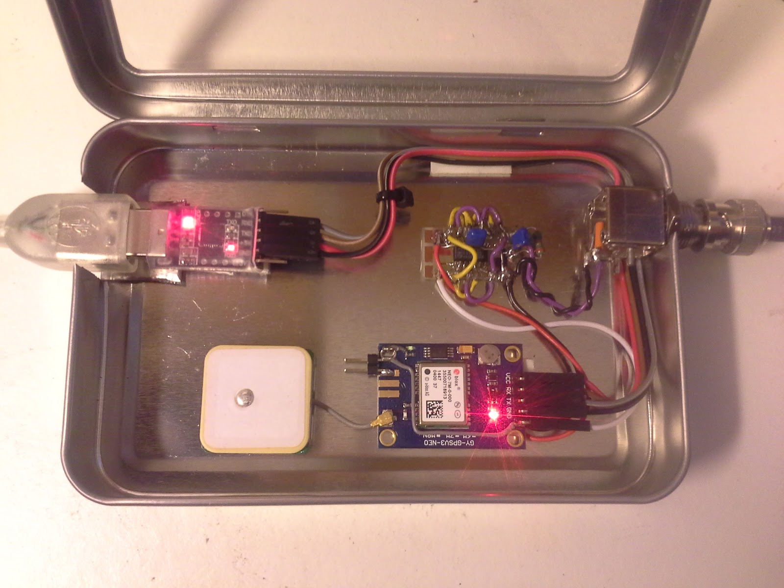
It definitely helped make indoors reception in my shack much more reliable. The first picture shows the unit with the 8.5 x 6.5 cm single-sided PCB ground plane attached with double-sided tape. The picture below shows it prior to adding the ground plane. I also added a small LED to the right so that I could see from the outside whether the GPS locks properly.
This post is a continuation of these other posts about the 10 MHz reference:
- Just good enough 10 MHz reference (3 Oct 2015)
- Better with SMA (15 Oct 2015)
- Curing amnesia in the 10 MHz GPS reference (19 Nov 2015)
Improved GPS reception with a ground plane
My poor-man’s 10 MHz reference based on the Ublox Neo-7M GPS module didn’t always receive GPS satellites. Since I rely on reception indoors, conditions were sometimes too marginal to lock the oscillator output to 10 MHz. Inspired by the QRPlabs GPS module of Hans Summers (G0UPL) with its large 6 x 6 cm PCB groundplane, I therefore decided to do something similar.
The first picture shows the unit with the 8.5 x 6.5 cm single-sided PCB ground plane attached with double-sided tape. It definitely helped make indoors reception in my shack much more reliable. In addition to the improved conditions for the patch antenna, it probably helps too that the antenna now is shielded from the digital circuitry of the GPS module, the 10 MHz pulse shaper, and the USB interface. I also added a small LED to the right so that I could see from the outside whether the GPS locks properly.
The second picture shows the interior prior to adding the ground plane.
This post is a continuation of these other posts about the 10 MHz reference:
- Just good enough 10 MHz reference (3 Oct 2015)
- Better with SMA (15 Oct 2015)
- Curing amnesia in the 10 MHz GPS reference (19 Nov 2015)
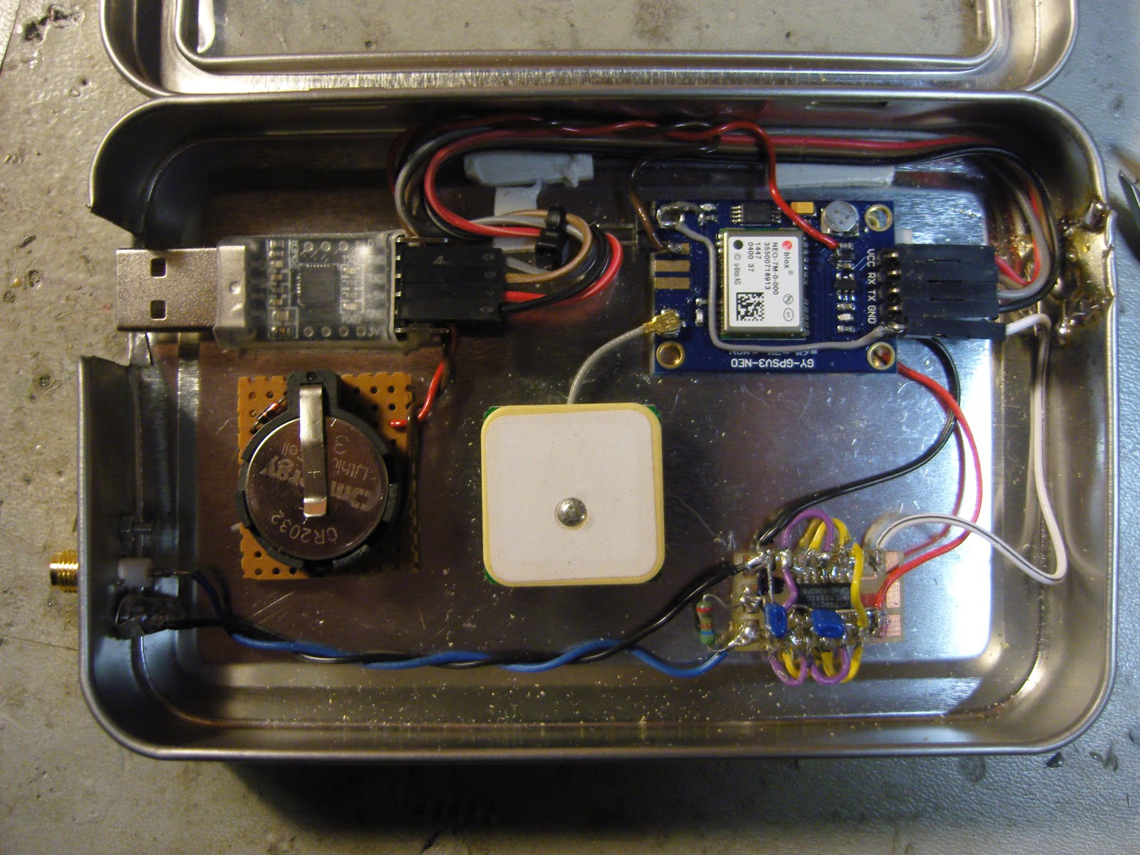
Curing amnesia on the 10 MHz GPS reference
 |
| Just good enough 10 MHz GPS reference with u blox Neo-7M GPS module to the upper right, 10 MHz output buffer lower right, USB interface to the upper left, CR2032 lithium battery center left, GPS antenna in the center, and SMA output connector lower left. |
My just good enough 10 MHz GPS reference which drives the external clock input on my Elecraft K3 kept losing its configuration if power was off for a day or so. I have therefore fitted a CR2032 3V lithium battery as seen to the left in this image.
It is connected in series with a 1N4148 diode in order to prevent attempts at charging the lithium cell. The connection goes to pin 22 (V_BCKP) as described by G4ZFQ on his website. The diode is visible to the upper left of the battery.
With this, I consider the 10 MHz reference to be finished.
Earlier related posts:
Curing amnesia in the 10 MHz GPS reference
|
| Just good enough 10 MHz GPS reference with u blox Neo-7M GPS module to the upper right, 10 MHz output buffer lower right, USB interface to the upper left, CR2032 lithium battery center left, GPS antenna in the center, and SMA output connector lower left. |
My “just good enough 10 MHz GPS reference” which drives the external clock input on my Elecraft K3 kept losing its configuration if power was off for a day or so. I have therefore fitted a CR2032 3V lithium battery as seen to the left in this image.
It is connected in series with a 1N4148 diode in order to prevent attempts at charging the lithium cell. The connection goes to pin 22 (V_BCKP) as described by G4ZFQ on his website. The diode is visible to the upper left of the battery.
With this, I consider the 10 MHz reference to be finished.
Other related posts:
Better with SMA
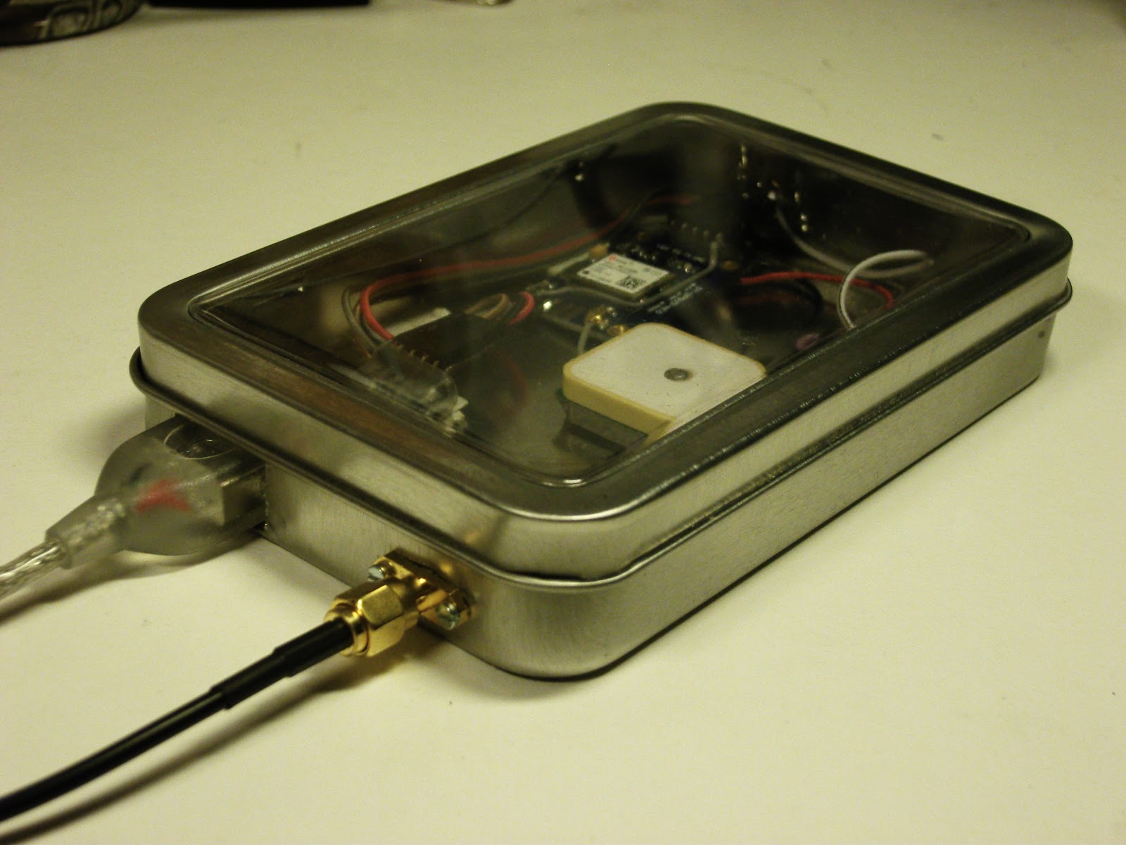
I had some trouble closing the lid on the “Just good enough 10 MHz GPS reference” due to the size of the BNC jack. Therefore I changed it to an SMA (SubMiniature version A) female jack. A thin cable connects it to the K3’s SMA input and there is no need for any SMA-BNC adapter on that end.
At the same time I moved the GPS antenna to a more central location in the tin, in the hope that the walls of the tin would interfere less with GPS reception. That’s the theory anyway, if it matters much in practice is a different story.
 Actually, I think I’m going to use SMA more often with these clear top tins and also Altoids tins. They take up much less space and are easier to install and to work with.
There aren’t any high power applications for circuitry in such tins, so I cannot so any reason why the SMA won’t work just as well or even better than the BNC.
Other related posts about the 10 MHz reference:
- Just good enough 10 MHz reference (3 Oct 2015)
- Curing amnesia in the 10 MHz GPS reference (19 Nov 2015)
- Improved GPS reception with a ground plane (11 April 2016)
Just good enough 10 MHz reference
Some time ago I noticed that the Ublox Neo-7M GPS has a 10 MHz output which was locked to the GPS system’s accuracy. Most people kept saying how much jitter it had and how useless it was unless it was cleaned up with a phase locked loop of some sort.
At the same time I got the 10 MHz reference input for my Elecraft K3 (K3EXREF). What struck me was how its function was described:
- The frequency of the internal oscillator of about 49.38 MHz oscillator would be continuously measured and averaged, obtaining a value to the nearest 1 Hz.
- The K3EXREF does not phase lock the K3’s reference oscillator and the external 10 MHz source has no impact on the K3’s phase noise performance.
This got me wondering if the Neo-7M would be just good enough as a reference and that all the averaging internally to the K3 would take care of its jitter. I ordered one from Ebay for USD 12-13 together with an USB interface (USD 1.5) and hooked it up. The result is shown above as assembled in a clear top tin. In my shack I can receive GPS indoors, so I have no need for an external antenna
 The K3 accepts the input and I see the star in REF*CAL blinking. Just after turn-on of the K3 my reference frequency ends in … 682 and after 10-15 minutes it has fallen and stabilized to …648, i.e. 34 Hz down in frequency. This is just 8 Hz off the reference value I determined manually was the right one when my K3 was new in 2009 (49,379,640).
All this taken together indicates to me that the K3 finds this 10 MHz acceptable for locking.
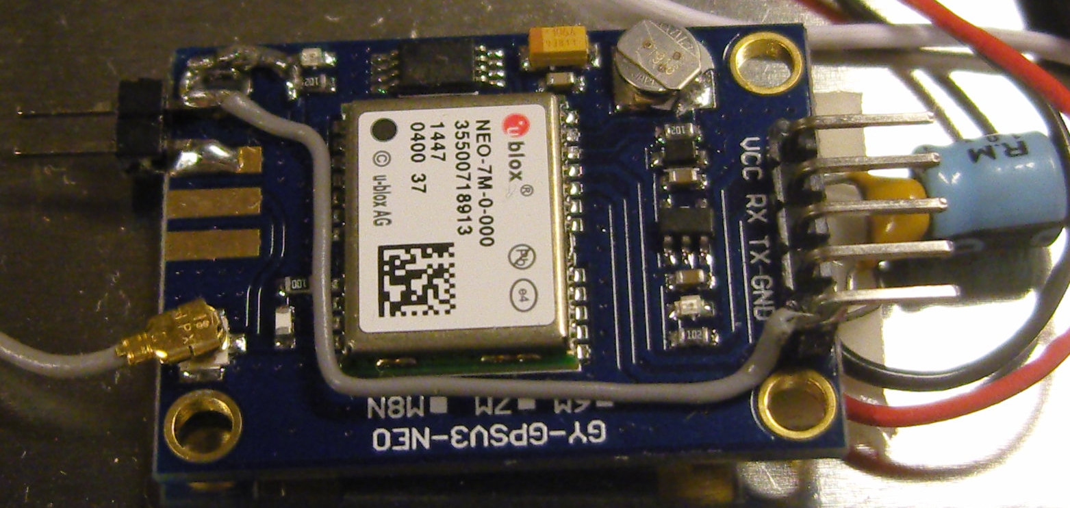
In order to get this to work I had to do some modifications to the GPS unit. First I had to get access to the timepulse on the chip’s pin 3. My connection is inspired by that of G4ZFQ and consists of a small wire to the upper left hole. From there another grey wire goes below the chip and to the 5-pin header which is soldered to the Vcc, Rx, Tx, Gnd pins. The 5th pin is cut off and is just attached to the other pins through the plastic hardware.
The second modification was required in order to get it to run from the somewhat noisy USB 5 Volt supply. That took some decoupling between the Vcc and Gnd pins (220 uF and 0.1 uF in parallel), visible to the right in the image above, using good engineering practice to keep the wires as short as possible.
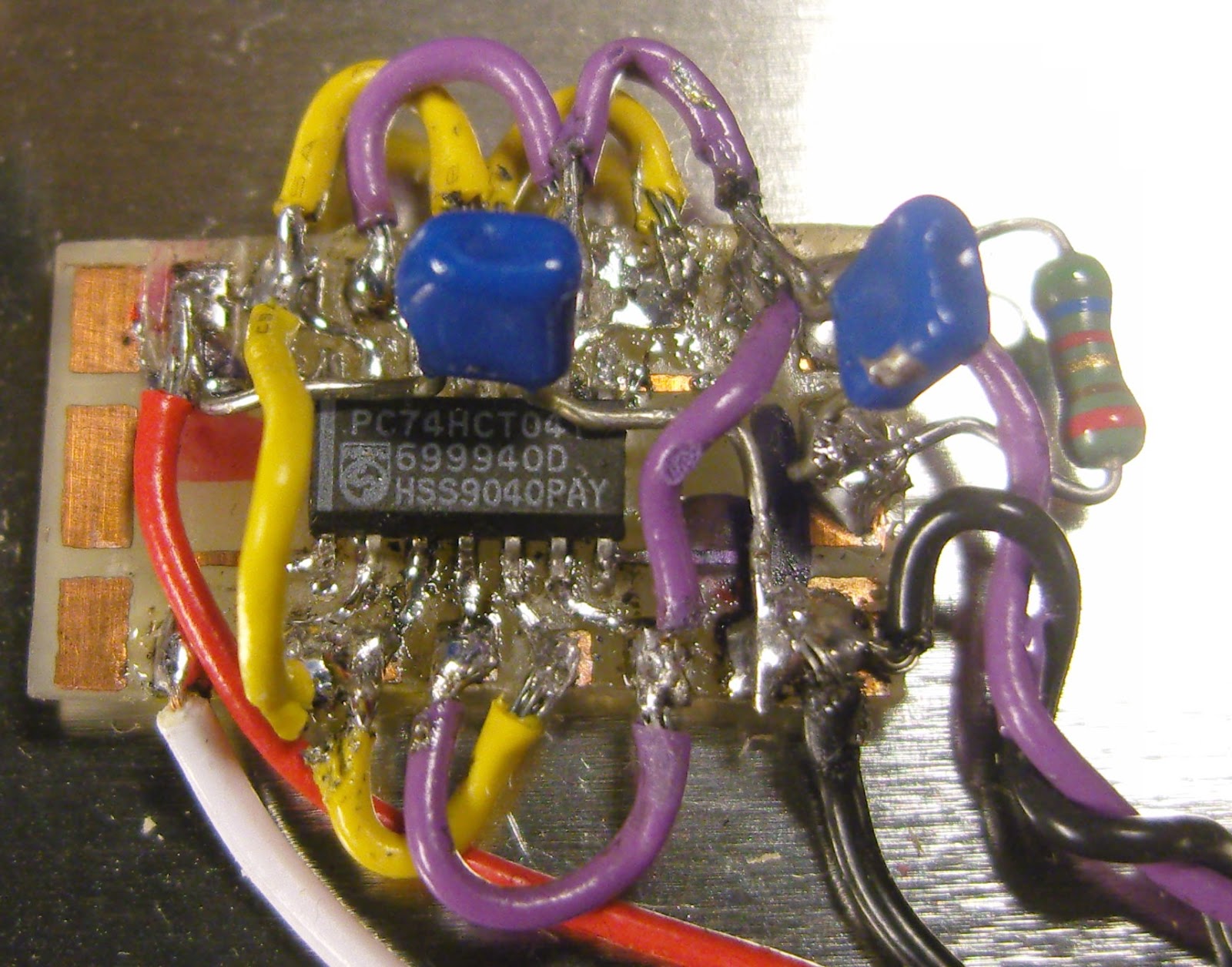 The timepulse is a 3.3 Vp-p output which cannot drive anything below 4-500 ohms impedance. Therefore I added a 74HCT04 driver that I have assembled on a little homemade SMD to DIL adapter PCB. It serves as a driver to feed the 10 MHz to the 50 ohm input of the K3EXREF.
The HCT04 IC has 6 inverters. One of them takes the input signal from the timepulse output of the GPS IC and buffers it to drive the 5 other inverters in parallel. This is shown in the schematics at the end of this blog post.
The 5Vp-p output from the buffers is fed via 56 ohms to a connector that goes to the K3EXREF input. This is in accordance with the K3EXREF manual which says: “The 10 MHz source should have a signal level between +4 dBm and +16 dBm, nominal. For square wave sources, 2VDC to 3.3VDC peak is optimum. If the source is a 5V logic level, use a 50-ohm resistor in series with the input.“
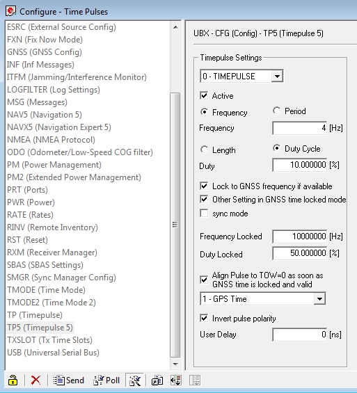 In order to set up the GPS I have used the u-center program (Menu: View, Configuration View, TP5 (Timepulse 5)) from Ublox and set it up with the parameters shown to the right. It blinks at 4 Hz before the signal is acquired and then switches to 10 MHz. This can be observed on the green LED connected to the Timepulse output also as it switches from blinking to a half-lit status.
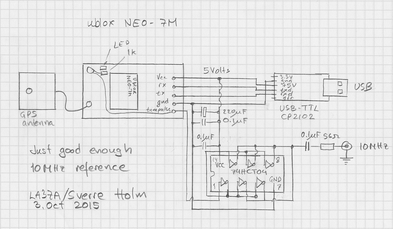
Just good enough 10 MHz GPS reference
Some time ago I noticed that the Ublox Neo-7M GPS has a 10 MHz output which is locked to the GPS system’s accuracy. Most people kept saying how useless it was due to excessive jitter unless it was cleaned up with a phase locked loop of some sort.
At about the same time I installed the external reference input for my Elecraft K3. The K3EXREF enables the K3’s frequency to be locked to an external 10 MHz reference. What struck me was how its function is described:
- The frequency of the internal oscillator of about 49.38 MHz is continuously measured and averaged, obtaining a value to the nearest 1 Hz.
- The K3EXREF does not phase lock the K3’s reference oscillator and the external 10 MHz source has no impact on the K3’s phase noise performance.
This got me wondering if the Neo-7M would be just good enough as a reference and that all the averaging internally to the K3 would take care of the jitter.I ordered one from Ebay for USD 12-13 together with an USB interface (USD 1.5) and hooked it up. (Actually the NEO-7M already has a built-in USB interface, but my board doesn’t support it). The result is shown above as assembled in a clear top tin. In my wooden house I can receive GPS indoors, so I have no need for an external antenna
The K3 accepts the input and I see the star in REF*CAL blinking. Just after turn-on of the K3 my 49.38 MHz reference frequency ends in …682 and after 10-15 minutes it has fallen and stabilized to …648, i.e. 34 Hz down in frequency. This is just 8 Hz off the reference value I determined manually was the right one when my K3 was new in 2009 (49.379.640).
All this taken together indicates to me that the K3 finds this 10 MHz acceptable for locking. The measurement to the nearest Hz, implies a measurement time of the order of 1 second and that seems to be enough to smooth out the jitter from the Neo-7M.
In order to get this to work I had to do some modifications to the GPS unit. First I had to get access to the timepulse on the chip’s pin 3. My connection is inspired by that of G4ZFQ and consists of a small wire from the left-hand side of the 1k resistor to the upper left hole. From there another grey wire goes below the chip and to the 5-pin header which is soldered to the Vcc, Rx, Tx, Gnd pins. The 5th pin is cut off and is just attached to the other pins through the plastic hardware.
The second modification was required in order to get it to run from the somewhat noisy USB 5 Volt supply. That took some decoupling between the Vcc and Gnd pins (220 uF and 0.1 uF in parallel), visible to the right in the image above, using good engineering practice to keep the wires as short as possible.
The timepulse is a 3.3 Vp-p output which cannot drive anything below 400-500 ohms impedance. Therefore I added a 74HCT04 driver that I have assembled on a little homemade SMD to DIL adapter PCB (easy to find on Ebay). It serves as a driver to feed the 10 MHz to the 50 ohm input of the K3EXREF.
The HCT04 IC has 6 inverters. One of them takes the input signal from the Timepulse output of the GPS IC and buffers it to drive the 5 other inverters in parallel. This is shown in the schematics at the end of this blog post.
The 5Vp-p output from the buffers is fed via 56 ohms to a connector that goes to the K3EXREF input. This is in accordance with the K3EXREF manual which says: “The 10 MHz source should have a signal level between +4 dBm and +16 dBm, nominal. For square wave sources, 2VDC to 3.3VDC peak is optimum. If the source is a 5V logic level, use a 50-ohm resistor in series with the input.“
In order to set up the GPS I have used the u-center program (Menu: View, Configuration View, TP5 (Timepulse 5)) from Ublox and set it up with the parameters shown to the right. It blinks at 4 Hz before the signal is acquired and then switches to 10 MHz. This can be observed on the green LED connected to the Timepulse output also as it switches from blinking to a half-lit status. See also


