 |
 Antenna repair work
always seems to be conducted when weather is less than optimal for such things.
You may remember me telling how I had to temporarily re-hang my 88′ EDZ wire last Saturday. Just a week ago, we were enjoying weather in the low 50s (11C), it was a good day to perform that task. But then during the week, I noticed it wasn’t working right and seemed to be deaf. I thought initially that there was a short in the PL-259 connector. I changed that out and it made no difference. I suspected a fault maybe a bit farther back in the coax, as feedlines always seem to be a probem, but then I thought – what if the problem is with the window line and not the coax?
So today, I headed outside and this weekend, the weather is quite a bit colder than last. In fact, it’s quite the opposite of last weekend. Last night we had a low of -3F (-20C) and today’s high was about 20F (-6C), so where did I find myself? Of course, in the back yard, freezing in the new fallen snow, inspecting my antenna to see where the fault might lay. And since I work better without gloves, that just added to the pleasure!
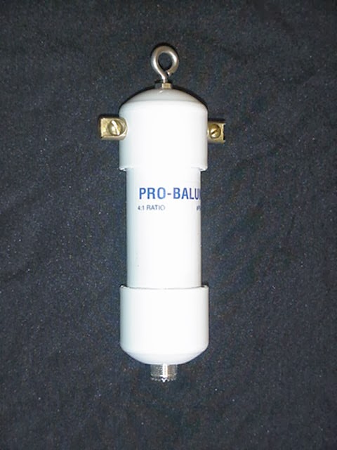
Fortunately, the fault was found quickly and it was an easy fix. When I was re-hoisting the antenna, the window line must have flexed and stressed badly at the BALUN terminals, and on one side, the wire had snapped. It proved to be a simple matter of loosening the screw, removing the old tiny bit of wire, stripping back a bit more of the insulation on that side of the window line and re-screwing the bare wire back down in place. I needed tools no more sophisticated than the Swiss Army Knife that I always carry. (You can’t work for a Swiss firm for 22 years of your life and NOT carry a Swiss Army Knife with you wherever you go.)
I went to my basement shack, where it’s a balmy 58F (15C) and was delighted to see the KX3 deliver a match in literally, just a couple of seconds. My preferred wire is now back in action and I am quite a happy camper. Now I just have to keep my fingers crossed that my temporary support line will hold for the rest of the winter!
72 de Larry W2LJ
QRP – When you care to send the very least!
Larry Makoski, W2LJ, is a regular contributor to AmateurRadio.com and writes from New Jersey, USA. Contact him at [email protected].
Getting old and ham radio……….
 |
| Keeping it simple |
 |
| 3x5 life savers |
Mike Weir, VE9KK, is a regular contributor to AmateurRadio.com and writes from New Brunswick, Canada. Contact him at [email protected].
What to do when WSJT tells you ‘invalid number of channels’
My excursion onto JT6M last night was a bit fraught, although ultimately very worthwhile and enjoyable. When I fired up WSJT, it errored – saying invalid number of channels.
I realised it was probably something to do with the fact that I had installed the VB-Cable audio driver onto the PC to route audio from the FCD to other applications. No worries, it’s just a simple case of adjusting the various device numbers.
Except that it wasn’t. Everything I tried still came up with the same error. WSJT-X was still working ok as was PZTLog, so I knew there wasn’t anything wrong with the interface or cabling. I disabled the VB-Cable driver, which put device numbers back where they originally were.No.
Starting to doubt my sanity which has been in question recently, anyway, I Googled it, realising that it was one of those times when the error was not what it seemed to be.
Fortunately I found this thread – thank you N0RQ! It looks like this can happen when you add or remove audio devices on your machine.
Deleted the WSJT.INI file, restarted WSJT, which of course creates a new INI file – entered my defaults and all was well!
A frustrating hour, but easily fixed once you know…
Tim Kirby, G4VXE, is a regular contributor to AmateurRadio.com and writes from Oxfordshire, England. Contact him at [email protected].
Struck by lightning
The night before last Olga and I nearly jumped out of our skins after a tremendous thunderclap which sounded as if it was just a few feet away. I wasn’t concerned for the radios as I didn’t think attic antennas would suffer from a lightning strike unless the house itself was struck but in any case both antenna switches were in the grounded position after I had heard thunder a few days earlier.
I checked both the K3 and the FUNcube Dongle which was the only other radio connected to an antenna and both seemed to be OK so I thought I had got off scot free.
That afternoon Olga noticed that the Netgear DECT Skype phones were not displaying the amount of money in the account. Later I tried to make a Skype call and was informed that Skype was offline We could still make landline calls from the phones but only if we dialled manually. Any attempt to call a number in the Contacts list using the landline received the message “The number you have dialled has not been recognised.”
Poking the Netgear base unit’s Reset button with a sharp stick didn’t solve the problem. It looks as if the SPH200D base unit is broken. I’m rather sorry about that because it’s an obsolete product and new ones are unobtainable – although eBay has a used one on offer for several times what it cost when new.
Olga uses Skype a lot to talk to relatives in Ukraine so it was very useful to have Skype connected all the time and not just when she was using the computer, but it’s looking as if we will have to live without that facility.
That evening we turned on the Humax Freetime box to watch some TV and there was no picture. We checked the voltage from the power supply, which is a small 12V 4A “brick rather than internal switched mode supply. Zero volts. We checked the fuse and that was intact. Unfortunately the Humax power supply has an unusual type of plug so I can’t use one of the collection 0f wall warts that I have in a box in the garage to test if the satellite receiver itself is working or whether it’s just the power supply that has failed.
There is no proof that lightning really did cause these items of equipment to fail – everything else including the broadband router are still working – but it’s quite a coincidence it it isn’t.. SoNow all I can do is wait until next week and order a new power supply from Humax. Oh happy days! At least we can still watch TV as I kept the old Freesat box as a backup.
Postscript. According to a neighbour a house a few streets away was damaged by the lightning bolt. Doesn’t seem near enough to have blown up two items of equipment though.
Julian Moss, G4ILO, is a regular contributor to AmateurRadio.com and writes from Cumbria, England. Contact him at [email protected].
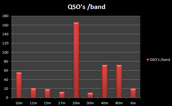
My Statistics for 2013

Paul Stam, PC4T, is a regular contributor to AmateurRadio.com and writes from the Netherlands. Contact him at [email protected].
My 2013 Radio Summary
How has the radio year 2013 been to you? Have you made additions to your shack? Did Santa bring you unexpected toys this year?
John Smithson, Jr., N8ZYA, is a regular contributor to AmateurRadio.com and writes from West Virginia, USA. Contact him at [email protected].
My first 50MHz JT6M Meteor Scatter QSO
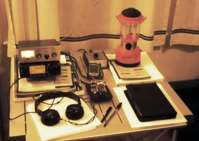
This evening, I was watching the tweets go by and realised that it was the peak of the Quadrantids meteor shower. Not having a 2m beam up at the moment, the only possibility was 50MHz. And though I have got my old 50MHz beam back from a friend who had it on long term loan, it’s not in a state to go up at short notice. So the only game in town is the V2000 vertical.
I wasn’t too worried as I had heard a few meteor bursts on the vertical in the past, so I guessed if there was any reasonable activity, I might hear something.
I quickly saw some bursts from an SM7 station and then a very considerable number from SK0TM up in JO86. So many, that I decided to go up to the shack, having been monitoring it all from the comfort of the sofa on the iPad.
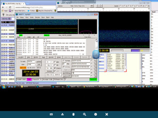
Very much tongue-in-cheek, I started to call SK0TM with a report. To my enormous surprise, I very quickly got a R26 report back so was able to send Rogers and receive them. By the time we got to try and exchange 73s, the conditions seemed to have dried up, but we both had all we needed for a complete QSO.
Thank you, Stig – I know it’s possible to make MS QSOs using simple aerials, but I’ve never done it with a vertical before!
Tim Kirby, G4VXE, is a regular contributor to AmateurRadio.com and writes from Oxfordshire, England. Contact him at [email protected].
 Ham Radio Deluxe |
 W5SWL Electronics |
 Ham Radio Prep |
 KB3IFH QSL Cards  Hip Ham Shirts  HamRadioAuctions HamRadioAuctions Reliance Antennas Reliance Antennas Enigma Shop Enigma Shop |  morseDX  Ni4L Antennas  R&L Electronics R&L Electronics antennas.us antennas.us QRV QRV |
- Matt W1MST, Managing Editor
