 |
 Yaesu FT991
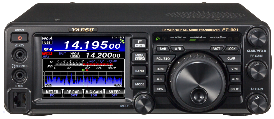
As I have said several times before, there is only one commercial rig that I fancy currently and that is the Yaesu FT991 that covers all of HF plus 6m, 2m and 70cm. However the UK price is still too high so I can wait and wait until the price drops. At £999 it will get serious consideration, but not at any higher price. The only other rig I fancy is an FT817 replacement, which may come later this year. Most of my operating is QRP and a 5-10W rig would suit my needs well.
Roger Lapthorn, G3XBM, is a regular contributor to AmateurRadio.com and writes from Cambridge, England.
2m big wheel

Well, I have ordered one (yes I know I could have made one although not in my present state) so I hope this can be erected in the next few weeks, although I shall need help to do this as I am no good on ladders in my current poor state of health. It would be good if I could get a long wire erected at the same time for LF/MF use, although this could wait. At this time I am going for a single big-wheel rather than a stack.
I have decided against buying a 70cm big wheel at the same time as this would require a new length of low loss cable too. I also checked my existing low loss cable and this seems in good condition, so it will be reused. I may make my combined 2m/70cm antenna into a portable antenna when I have found out why the VSWR is poor.
See https://sites.google.com/site/g3xbmqrp3/antennas/bigwheel .
Roger Lapthorn, G3XBM, is a regular contributor to AmateurRadio.com and writes from Cambridge, England.
SKCC Sprint
 I've spent a couple of hours this weekend (so far mainly on Saturday), playing in the SKCC Sprintathon CW contest ... the rules demand that only hand keys, including bugs, be used. I hauled out my original gray Vibroplex, purchased back in 1964, when I decided that using a straight key was just too slow. I was doing a lot of DXing and contesting back then, with my trusty DX-20, VF-1 VFO and assorted groundplanes on top of my parents three-story house in the middle of Vancouver ... it's hard to believe that it was quiet enough there but those were the days before computers, switching power supplies and and so many other noise-making devices that we have today. They truly were the 'good old (quiet) days' of radio. My favorite contests back then were the 'W-VE', where any 'VE' became instant DX and the subject of good-sized pileups and the CW 'Sweepstakes' ... back when the exchange was, if I recall correctly, just NR, RST and QTH.
 My antenna farm sat on our high, peaked roof and consisted of groundplanes for 40m, 20m and 15m ... these were made of inexpensive galvanized drain pipe, about three or four inches in diameter. The 40m one was guyed and also had one end of my 80m dipole attached to it, which ran out across the yard and across the back lane, terminating on one of BC Hydro's wooden (telephone) poles. Every once in a while the telephone guys would take it off and toss it over the fence whereupon I would get out the ladder and re-attach it, where it would stay for another year or so.
For this weekend's CW party, I have put my 'Tri-Tet-Ten' on 20m, doubling from a 40m crystal to 14051.5, placing me pretty close to the Sprint's watering-hole QRG of 14050. I have had way too much fun with this simple one-tube radio since building it, mainly for 10m CW, in anticipation of the present solar cycle's peak years. Although it puts out almost 5W when quadrupling to 10m, I can get a whopping 13W from it on 20m, which is plenty of power to have some fun.
So far I've worked about 40 stations, all on CQ's, since I can't really QSY to answer others ... so if you are around this afternoon, please give me a call should you hear my little rig. It's a real nice change to hear non-machine sent CW for a change and fists ranging from one end of the scale to the other ... really a nice reminder of what the bands used to sound like when I first got on the air.
Steve McDonald, VE7SL, is a regular contributor to AmateurRadio.com and writes from British Columbia, Canada. Contact him at [email protected].
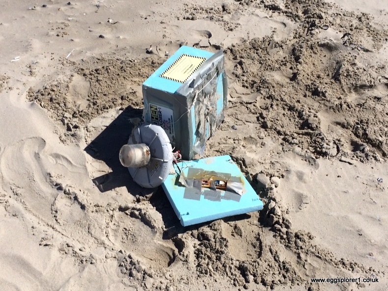
MADHEN Eggsplorer-1 FOUND!
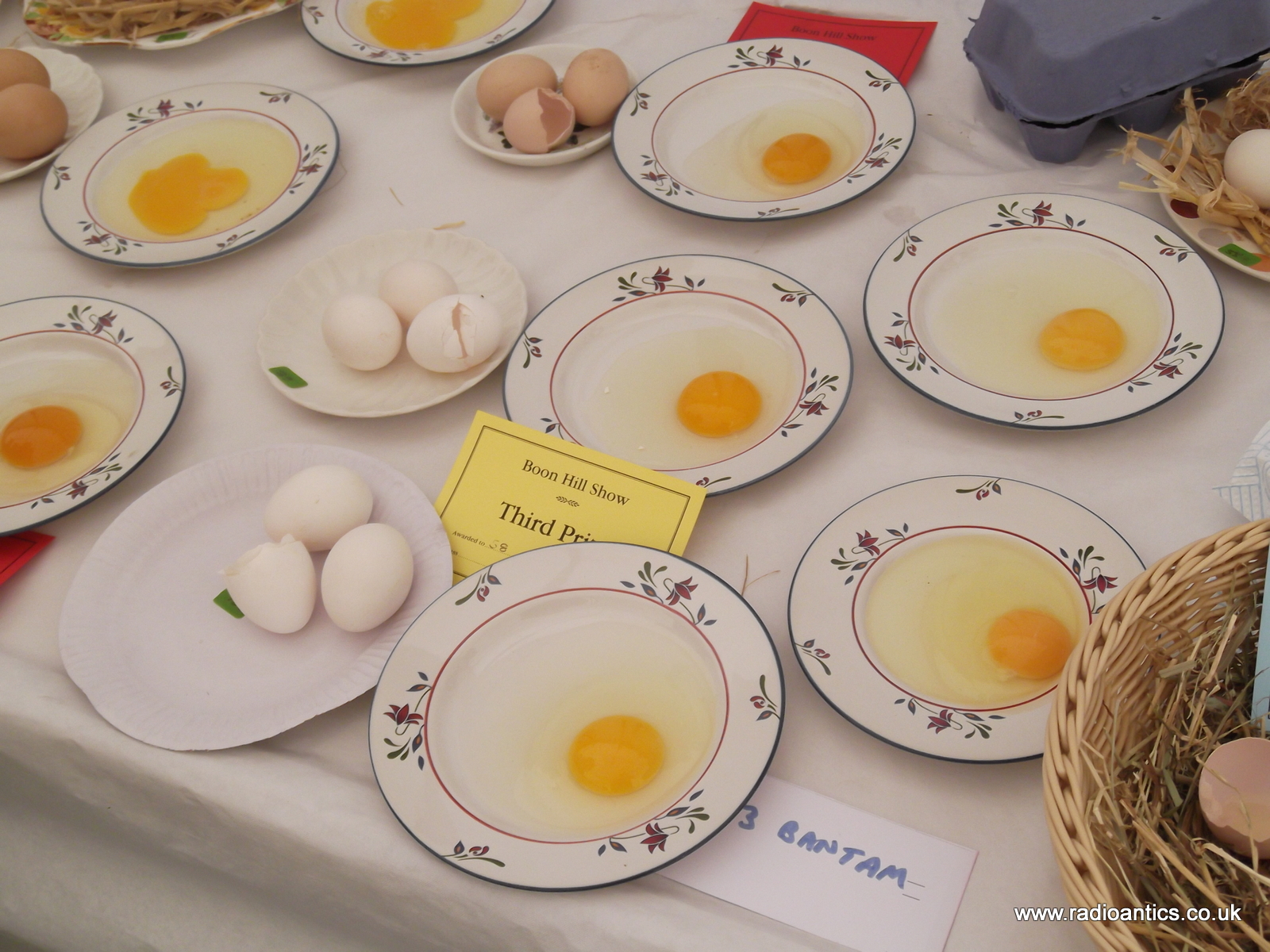
On Friday evening I went to the Hucknall Rolls Royce ARC to give a presentation of HAB flights including details of the Eggsplorer-1 launch and its subsequent apparent loss at sea, then yesterday we had a trip to North Yorkshire and visited the Boon Hill Show and I admired the display of eggs within the produce tent.
It must have been synchronicity since a few hours later despite the poor mobile phone coverage I spotted a message on my mobile phone. It was from Jan Wouter Kramer from the Netherlands, whilst out on a remote beach in Terschelling he had found the Eggsplorer-1 washed up and taken some photographs!
Nearly six weeks to the day after launch she had been found with the egg apparently intact! I tried several times to ring back but the poor mobile coverage prevented it so sent a text message hoping it would reach him. I couldn't wait to get home to and finally did just before midnight.
I frantically logged on to check emails
Hey AndrewThe pictures were amazing
Found your email on the site.
These are the pics we made.
We found it today about 14:00 during a walk on the beach of Terschelling in an area were not many people are walking because it's more than a two hours walk from the nearest houses.
As you can see the egg wasn't damaged but had probably lost it's strength. While trying to investigate what was inside the 'bulb' it broke open and the egg broke in two parts. It was nearly empty. Only a few cc of dark 'water' was left in it with a terrible smell .......
Best Regards !
Jan Wouter Kramer


I emailed Jan back as far too late in the night to telephone
Hi Jan,
As I wrote given the remoteness and the rancid condition of the egg I couldn't really expect Jan to go out again to collect it but had a fantastic text message this morningAndrew Garratt (M0NRD)RegardsThe Raspberry PI circuit board inside the box had a SD memory card which was held down with gaffa tape, I am not sure if it is still attached and it may have contained some photos of the flight taken with the onboard camera. However given the remoteness of the payload I understand if it is too far to return for such a slim chance.Amazingly it appears very much intact, shame about the egg being rancid, would really have liked to get it back and would have paid for shipping - but I can imagine the smell was awful.Sorry I was able to take your call this afternoon but was out of coverage for most of the day.Thank you very much for the information and pictures of the Eggsplorer-1. It was our first ever balloon flight and after it landed in the sea I thought we would never see it again.
Hi Andrew, thanks for your email. The good news is that I found the local police willing to pick up the remains of the eggsplorer. (They are allowed to drive on the beach by 4x4) I just got a phonecall that they found it and are willing to send it back to you.As you can imagine I am totally EGGSTATIC!!
So you have an address for me ??
Best regards
Jan Wouter
I rang Jan this morning and had a great conversation, seems he visits here every year and goes beach-combing with his son, they have never found anything quite as exciting as this!
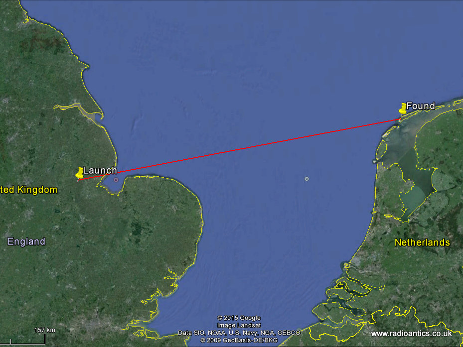
So MADHEN Eggsplorer-1 has traveled 31km into the stratosphere, landed in the sea and traveled approximately 370km from launch site to its final resting place on the beach. The World Egg Throwing Championship people are very eggcited.
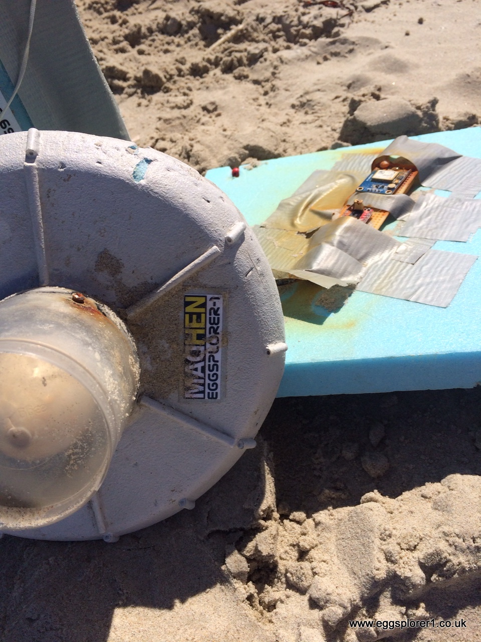
Just hoping that there are some photos on the card if it has survived, cannot be sure from Jan's photographs. Since the flight I have suspected two possible fault scenarios, bad connector on the SD card on the Raspberry Pi or the antenna was broken off due to the backup tracker suspended underneath. I am hoping it was the latter and the card is recoverable and readable since it would contain pictures.
The backup tracker is also there but has lost its polystyrene egg cover, gps-antenna and battery pack but can see it is still attached to the main payload. The question is how long it has been on the beach? Given the relatively good condition of the box and the labels are still attached it may have been quite soon after splash down.
I am indebted to Jan for taking the trouble of contacting me and the police, I can't thank him enough! When I get the payload back I will post an update.
All the members of SKARS are eggcited and gives new impetus for the National Hamfest flight next month.
Andrew Garratt, MØNRD, is a regular contributor to AmateurRadio.com and writes from East Midlands, England. Contact him at [email protected].
MADHEN Eggsplorer-1 FOUND!
On Friday evening I went to the Hucknall Rolls Royce ARC to give a presentation of HAB flights including details of the Eggsplorer-1 launch and its subsequent apparent loss at sea, then yesterday we had a trip to North Yorkshire and visited the Boon Hill Show and I admired the display of eggs within the produce tent.
It must have been synchronicity since a few hours later despite the poor mobile phone coverage I spotted a message on my mobile phone. It was from Jan Wouter Kramer from the Netherlands, whilst out on a remote beach in Terschelling he had found the Eggsplorer-1 washed up and taken some photographs!
Nearly six weeks to the day after launch she had been found with the egg apparently intact! I tried several times to ring back but the poor mobile coverage prevented it so sent a text message hoping it would reach him. I couldn't wait to get home to and finally did just before midnight.
I frantically logged on to check emails
Hey AndrewThe pictures were amazing
Found your email on the site.
These are the pics we made.
We found it today about 14:00 during a walk on the beach of Terschelling in an area were not many people are walking because it's more than a two hours walk from the nearest houses.
As you can see the egg wasn't damaged but had probably lost it's strength. While trying to investigate what was inside the 'bulb' it broke open and the egg broke in two parts. It was nearly empty. Only a few cc of dark 'water' was left in it with a terrible smell .......
Best Regards !
Jan Wouter Kramer
I emailed Jan back as far too late in the night to telephone
Hi Jan,
As I wrote given the remoteness and the rancid condition of the egg I couldn't really expect Jan to go out again to collect it but had a fantastic text message this morningAndrew Garratt (M0NRD)RegardsThe Raspberry PI circuit board inside the box had a SD memory card which was held down with gaffa tape, I am not sure if it is still attached and it may have contained some photos of the flight taken with the onboard camera. However given the remoteness of the payload I understand if it is too far to return for such a slim chance.Amazingly it appears very much intact, shame about the egg being rancid, would really have liked to get it back and would have paid for shipping - but I can imagine the smell was awful.Sorry I was able to take your call this afternoon but was out of coverage for most of the day.Thank you very much for the information and pictures of the Eggsplorer-1. It was our first ever balloon flight and after it landed in the sea I thought we would never see it again.
Hi Andrew, thanks for your email. The good news is that I found the local police willing to pick up the remains of the eggsplorer. (They are allowed to drive on the beach by 4x4) I just got a phonecall that they found it and are willing to send it back to you.As you can imagine I am totally EGGSTATIC!!
So you have an address for me ??
Best regards
Jan Wouter
I rang Jan this morning and had a great conversation, seems he visits here every year and goes beach-combing with his son, they have never found anything quite as exciting as this!
So MADHEN Eggsplorer-1 has traveled 31km into the stratosphere, landed in the sea and traveled approximately 370km from launch site to its final resting place on the beach. The World Egg Throwing Championship people are very eggcited.
Just hoping that there are some photos on the card if it has survived, cannot be sure from Jan's photographs. Since the flight I have suspected two possible fault scenarios, bad connector on the SD card on the Raspberry Pi or the antenna was broken off due to the backup tracker suspended underneath. I am hoping it was the latter and the card is recoverable and readable since it would contain pictures.
The backup tracker is also there but has lost its polystyrene egg cover, gps-antenna and battery pack but can see it is still attached to the main payload. The question is how long it has been on the beach? Given the relatively good condition of the box and the labels are still attached it may have been quite soon after splash down.
I am indebted to Jan for taking the trouble of contacting me and the police, I can't thank him enough! When I get the payload back I will post an update.
All the members of SKARS are eggcited and gives new impetus for the National Hamfest flight next month.
Andrew Garratt, MØNRD, is a regular contributor to AmateurRadio.com and writes from East Midlands, England. Contact him at [email protected].
Amateur Radio Weekly – Issue 72

FreeDV QSO Party Weekend
The Amateur Radio Experimenters Group would like to invite all amateurs interested in HF digital voice communications to join us on the weekend of September 12th and 13th in a FreeDV Codec2 digital HF voice QSO Party!
AREG
Do not Digipeat via PCSAT
Although this is the correct frequency for APRS operation in IARU Region 2, it is not compatible with our Region 1 bandplan.
AMSAT UK
My Amateur Radio bucket list. What’s yours?
There is just so many possible things you can do within the hobby that it could possibly take a lifetime to achieve.
NT1K
Chinese Amateur Radio Satellites set to launch in early September
The XW-2 series satellites are equipped with substantially identical Amateur Radio payloads — a U/V mode linear transponder, a CW telemetry beacon and an AX.25 19.2k/9.6k baud GMSK telemetry downlink.
ARRL
Simplex, Duplex, Offset and Split
Simplex is a term that applies on all of the ham bands, because it is the simplest way to communicate. However, it is not the “opposite” of using a repeater.
Ham Radio School
What happened when I added a counterpoise to my HT
By adding a 1/4-wave counterpoise, you, in effect, turn the antenna into an off-center-fed, vertically polarized 1/2-wave dipole.
KC4LMD
Facebook. What is it good for?
Notable Amateur Radio Facebook Groups.
W2LJ
DX from Bald Ledge
EA5GX Sergio in Spain was calling CQ and we made a quick contact. There was some QSB, but he gave me a 579. Finally, I heard LZ1GU in Bulgaria calling CQ. Harry was strong and he gave me a 569.
amateurradio.com
In Pacific islands, radio remains the most accessible news source
Newspapers are a luxury item. On average, each newspaper in the Pacific will be read by seven people, which helps explain why the daily paper’s print run is so low.
The Saturday Paper
How to
QRV from a new apartment
This mainly amounted to mounting and tuning my 20m hamstick and running cable to the radio. This doesn’t sound like much on paper but it was a lot more engineering than that.
W0EA
Video
Ham Radio fun with tropospheric ducting propagation
This is a sample of stations I worked or heard during a nice tropospheric ducting 2 meter band opening from my location in Albert Lea, Minnesota.
RadioHamGuy
Homemade yagi antenna field test
I demonstrate some local QRM that I have been receiving there, check access to 4 distant repeaters (GB3SC, GB3JB, GB3WH and GB3VA), and have a nice QSO with Andy (G6TRW).
YouTube
Amateur radio enthusiast contacts space station
We live in a world fascinated by space, but very rarely does the ordinary man reach up into the stars for a chat.
CNN
Amateur Radio Weekly is curated by Cale Mooth K4HCK. Sign up free to receive ham radio's most relevant news, projects, technology and events by e-mail each week at http://www.hamweekly.com.
Series Eight Episode Seventeen – Amateur Radio Ebay Reviews (9 August 2015)
In this episode, Martin M1MRB / W9ICQ is joined by Ed Durrant DD5LP ,Martin Rothwell M0SGL and Matthew Nassau 2E0MTT to discuss the latest Amateur / Ham Radio news. Colin M6BOY rounds up the news in brief, and this episodes feature is Ed’s Ebay purchases reviews and antennas.
- Proposed $1000 fine for Identifying Ham Radio Stations
- NoVs Changes for UK Intermediate Amateur Radio Operators
- Amateur Radio Vanity Call Sign Fee to Disappear in September
- Low Cost Device lets Hackers Hijack Satellite and Amateur Radio Satellite Communications
- Special Event Station Host for YOTA Required
- SignaLink and Other USB Digital Interfaces – Huge Bug + Fix for Amateur Radio Digital Modes
- Bogus Ofcom Email targets UK Amateur Radio Operators
- Amateur / Ham Radio Celebration and Promotion of Marine Beacons
- New Radio Initiative Website
- Radiomart.co.uk - New Classifieds Site
- Essex gets 2m D-STAR Amateur Radio Repeater
Colin Butler, M6BOY, is the host of the ICQ Podcast, a weekly radio show about Amateur Radio. Contact him at [email protected].
 Ham Radio Deluxe |
 W5SWL Electronics |
 Ham Radio Prep |
 KB3IFH QSL Cards  Hip Ham Shirts  HamRadioAuctions HamRadioAuctions Reliance Antennas Reliance Antennas Enigma Shop Enigma Shop |  morseDX  Ni4L Antennas  R&L Electronics R&L Electronics antennas.us antennas.us QRV QRV |
- Matt W1MST, Managing Editor
