 |
 Project updates
The last few weeks have been very productive on the ham radio front! I cleaned up the coax routing for my Icom 2820 I had installed in the new pickup. While it was only slightly messy, the extra tie wraps and cable management make me feel better. I also installed a GPS puck antenna so the 2820 now shows my position on every D-STAR transmission I make. I had this setup with the 880 in the previous truck, but never had this setup on the 2820. It was very simple – plug in the antenna, change a few settings, and you’re good to go. I used a $10 antenna from Amazon.
I moved the antenna for my FlightRadar24.com ADS-B feed radio to a higher location at the end of the pole barn. This required also moving the ubiquiti 2GHz data radio I use to provide internet access to the radio. Luckily I had enough spare mast clamps and hardware to turn this into a nice afternoon project.
At the WX9WX D-STAR homebrew repeater site, the building owner called and wanted our AREDN mesh antenna moved a bit higher. The initial request was for the antenna to be low enough that it couldn’t be seen from the road. Now we needed to move it higher so that workers on the roof wouldn’t be at eye level with the transmitter. Having worked in the corporate world for quite some time, changing requirements or expectations is something I’m used to. So up to the roof we went, and up another 6 feet went the antenna!
This week Tom KJ9P and I moved the repeater to its newly coordinated frequency. Changing the frequencies on the Motorola radios was a piece of cake thanks to software and a laptop. Re-tuning the duplexer at the site was more of a challenge. I’ve tuned quite a few duplexers in the last three years, but never one at a site. I found that without a portable signal generator that could go down in the microvolts, it was difficult to do the precise tuning I normally do on the bench. Luckily a quick phone call to Fred KC9REG, who was 27 miles away, resulted in an EXCELLENT weak signal for final testing!
The next projects involve cleaning up the shack. Does anyone ever finish cleaning up the shack? Maybe I should lower my expectations. Finally, I must get an antenna up for 160m before the winter. Plans for a skywire loop are underway. Now to find 600′ of 12 gauge wire and some ladder line…
Michael Brown, KG9DW, is a regular contributor to AmateurRadio.com and writes from Illinois, USA. Contact him at [email protected].
Project updates
The last few weeks have been very productive on the ham radio front! I cleaned up the coax routing for my Icom 2820 I had installed in the new pickup. While it was only slightly messy, the extra tie wraps and cable management make me feel better. I also installed a GPS puck antenna so the 2820 now shows my position on every D-STAR transmission I make. I had this setup with the 880 in the previous truck, but never had this setup on the 2820. It was very simple – plug in the antenna, change a few settings, and you’re good to go. I used a $10 antenna from Amazon.
I moved the antenna for my FlightRadar24.com ADS-B feed radio to a higher location at the end of the pole barn. This required also moving the ubiquiti 2GHz data radio I use to provide internet access to the radio. Luckily I had enough spare mast clamps and hardware to turn this into a nice afternoon project.
At the WX9WX D-STAR homebrew repeater site, the building owner called and wanted our AREDN mesh antenna moved a bit higher. The initial request was for the antenna to be low enough that it couldn’t be seen from the road. Now we needed to move it higher so that workers on the roof wouldn’t be at eye level with the transmitter. Having worked in the corporate world for quite some time, changing requirements or expectations is something I’m used to. So up to the roof we went, and up another 6 feet went the antenna!
This week Tom KJ9P and I moved the repeater to its newly coordinated frequency. Changing the frequencies on the Motorola radios was a piece of cake thanks to software and a laptop. Re-tuning the duplexer at the site was more of a challenge. I’ve tuned quite a few duplexers in the last three years, but never one at a site. I found that without a portable signal generator that could go down in the microvolts, it was difficult to do the precise tuning I normally do on the bench. Luckily a quick phone call to Fred KC9REG, who was 27 miles away, resulted in an EXCELLENT weak signal for final testing!
The next projects involve cleaning up the shack. Does anyone ever finish cleaning up the shack? Maybe I should lower my expectations. Finally, I must get an antenna up for 160m before the winter. Plans for a skywire loop are underway. Now to find 600′ of 12 gauge wire and some ladder line…
Michael Brown, KG9DW, is a regular contributor to AmateurRadio.com and writes from Illinois, USA. Contact him at [email protected].
AmateurLogic Live
Join us this Saturday night, September 12th, 7PM CDT, 000 UTC at live.amateurlogic.tv . We’ll be shooting episode 82 of AmateurLogic. We’ve got stuff from Huntsville you haven’t seen yet, details about our 10th Anniversary contest and more.
George Thomas, W5JDX, is co-host of AmateurLogic.TV, an original amateur radio video program hosted by George Thomas (W5JDX), Tommy Martin (N5ZNO), Peter Berrett (VK3PB), and Emile Diodene (KE5QKR). Contact him at [email protected].
70cm contest using a 2m big wheel
 |
| Stations worked on 70cm tonight with 5W and a 2m big-wheel omni |
This evening was the September 70cm leg of the RSGB’s UKAC contest, so I decided to give it a go with my 2m big-wheel and 5W SSB. The match on 70cms was very good, but I had no idea how it would actually work. Well, the answer is “very well” as you can see by the stations worked. Best DX was 182km. To say I was pleased is an under-statement! I shall be able to use this antenna again in 70cm contests. I was also able to copy the new beacon NW of Leicester GB3LEU which was pretty good copy on 432.490MHz.
Roger Lapthorn, G3XBM, is a regular contributor to AmateurRadio.com and writes from Cambridge, England.
New Lightwave Modulator
 Yesterday I completed the construction of the crystal-controlled tone generator which will be used to modulate my lightwave transmitter during future clear-air / cloudbounce tests.
 It was installed on the lightbox, right beside the original 556 CW beacon / tone generator.


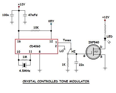
The crystal-controlled oscillator uses a CD4060 IC as an oscillator-divider and produces a ~550Hz or a ~1098Hz squarewave from the 4.5MHz crystal.
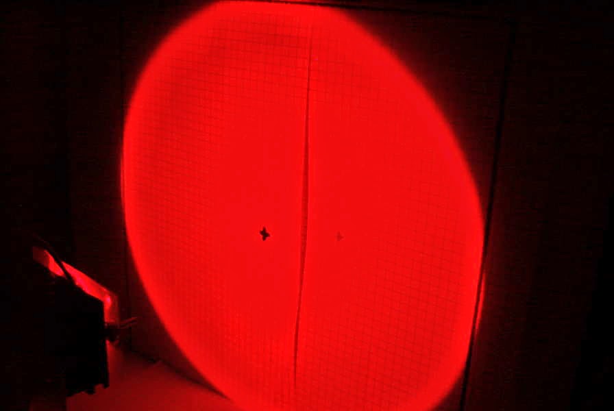
 |
| 4500KHz xtal divided by 8192 showing 549Hz output |
As can be seen by comparing the two oscillators (crystal on the left and 556 on the right), the 556 has a lot of drift (although it looks like it might eventually stabilize) and, as well, produces several spurious signals ... probably robbing power from the main tone. The crystal-controlled signal is rock solid and doesn't appear to generate any parasitic signals in the process. The trace below the crystal signal is unrelated to the oscillator.
When I first wired the unit up, I found an unstable low frequency oscillation from the 4060 during key-up conditions, due no doubt, to the lengthy leads inside the box. This was cured by adding a pull-up resistor to the keying line as shown in the final schematic below.
Now it's on to building another fresnel-lens receiver box which will be needed for any field work here on the island.
Steve McDonald, VE7SL, is a regular contributor to AmateurRadio.com and writes from British Columbia, Canada. Contact him at [email protected].
Toyota Transition
This blog started in conjunction with my return to the United States in 2005 and purchase of a Toyota Tundra. After being away from the US for four years, I celebrated my return by the purchase of the new truck and a (mostly) circumnavigation of the lower 48. My first encounter with Toyota was through my friend Robb and a 1980s Toyota 4×4 he had. Robb was going to school at Cal Poly, San Luis Obispo. Robb was fond of taking his truck to Pismo Beach and enjoying the beach and dune experience. Robb loved his truck.
After spending a year in Monterrey, CA learning Russian at the Defense Language Institute and a few months honing my listening abilities at Goodfellow Air Force Base near San Angelo, TX, I got my follow on orders to Fairbanks, Alaska (Fort Wainwright). I didn’t have a car. I was an enlisted Army soldier making not a whole lot of money. Heading way, way up north. I figured I needed a 4-wheel drive vehicle to make my life a bit more comfortable. My first thought was a Ford Ranger. But it ended up being too expensive. The most reasonable costing 4-wheel drive vehicle was a Toyota 4×4. It was 1993 and the Tacoma had not come along yet. 1993 Toyota 4×4. Manual locking hubs. Manual windows. AM/FM radio. Bench seat. No A/C. 4 cylinders. That truck was to go on to perform flawlessly in Alaska, transported me from Alaska to Georgia and several cross-country trips. Arizona. Washington State. Texas. And California. For seven years, that truck never let me down. I was heading off to Korea for a year to be followed by three in Germany. I sold the truck.


When I was planning my return to the US, I knew I wanted to get another Toyota. I settled on the Tundra. But instead of the minimum package, I was able to swing a 2005 Toyota Tundra Limited Double Cab 4×4. This truck offered to support a newly forming family. I broke the truck in with a trip around the US. I continually upgraded my ham radio installation in the truck, further enhancing my mobile enjoyment. The Tundra performed flawlessly. Never an issue.


The Tundra proved to be the hero of the 2015 Summer trip. Five national parks. From Kansas to Montana, Wyoming, out to California and back. Pulling a travel trailer. No issues, no problems. Over 120,000 miles.

It was time to think about the future. A future of summer travel. Exploration of national parks in the west. Colorado. Arizona. Utah. Maybe an upgrade to the travel trailer. The 2005 Tundra had an older drive train and a towing capacity topping out at 4,200 lbs. Comparing the aging 2005 Tundra to the current available 4x4s… the 2005 had a hard time measuring up.
I wanted to find something that was as reliable and dependable. Offered increase towing capability. But maybe smaller? Truth be told, I often had difficulty parking the Tundra. The turning radius was… challenging. Was there something available in a smaller package, yet offering increased performance and towing capabilities? Oh… did I mention that it has to be a Toyota?
Scott Hedberg, NØZB, is a regular contributor to AmateurRadio.com and writes from Kansas, USA. Contact him at [email protected].
State QSO Parties
 I spent a couple of hours again this weekend playing with the N1MM contest logging software and getting back into the contesting groove. My new K1EL USB interface continues to work flawlessly, even on my ancient XP laptop ... gone are the occasional keying stutters produced when previously keying from the serial port. N1MM is one of the most widely-used contest loggers and is freely available for download here. I still run the older 'Classic' version as I don't think my laptop could handle the newer 'N1MM +' edition ... I'll upgrade when I get a newer contesting laptop.
Both the Colorado and the Tennessee State QSO Parties were held this weekend, providing me another round of CW contest practice. Both activities are pretty low-key affairs when it comes to contesting but hey, every bit of practice helps.
I found surprisingly little action in the CO Party, making just 18 contacts ... 12 on 20m CW and 6 on 40m, with 17 sections worked. There seemed to be more activity from TN amateurs though, with 38 QSO's in 33 sections, 28 on 20m and 10 on 40m. All contacts were made on CW. All of the 40m contacts were made several hours before local sunset here, surprising the heck out of me that the W4's could even hear me in broad daylight ... the stations worked must have very quiet locations.
The state QSO parties are a good way to enjoy a short round of contesting without blowing an entire weekend, which I don't think I would really like to endure, and there seems to be at least one or two of them each weekend ... an easy way to ease into contesting or to keep up your on-the-fly contest keyboarding skills.
Steve McDonald, VE7SL, is a regular contributor to AmateurRadio.com and writes from British Columbia, Canada. Contact him at [email protected].
 Ham Radio Deluxe |
 W5SWL Electronics |
 Ham Radio Prep |
 KB3IFH QSL Cards  Hip Ham Shirts  HamRadioAuctions HamRadioAuctions Reliance Antennas Reliance Antennas Enigma Shop Enigma Shop |  morseDX  Ni4L Antennas  R&L Electronics R&L Electronics antennas.us antennas.us QRV QRV |
- Matt W1MST, Managing Editor
