 |
 QRV on VHF digimodes using a ZLP interface
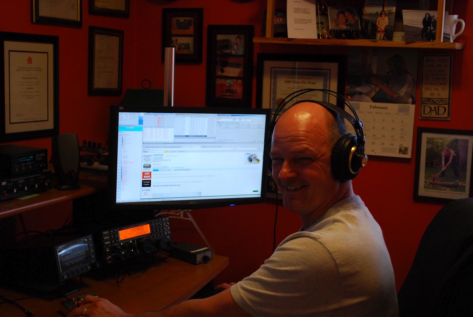
If you’ve been reading the blog for a while, you’ll know that I have been keen to get going on the VHF datamodes, particularly the WSJT modes. I’d been thwarted up until now by the lack of an interface and I’d been reluctant to part with money until I could verify that things ought to work ok! I’d had some bad experiences with the FT-847 and interfaces in the past.
The random trigger for getting this sorted out was seeing a tweet from Colin G6AVK on Twitter that he had ordered a ZLP interface for his laptop. I hastily Googled ZLP Electronics and discovered a range of interfaces very competively priced. I e-mailed Neil, G4ZLP to ask his advice about interfacing with the FT-847 and he recommended the Pro Plus interface. On the basis of his advice I placed an order.
Two days later it arrived, well packaged. Getting the FT-847 setup proved very simple indeed – although I’d had a bit of fun and games getting the levels right from the Pro Plus interface to my FT1000MP. However, it was the VHF/UHF rig that I really wanted to interface with.
Armed with the interface and the WSJT software, I popped onto the ON4KST chat server to see if anyone was around to try a JT6M test with. Although I only have the vertical up, I thought it would probably yield some results. And so it proved, as I was quickly able to exchange signals with Pat, EI8IQ on 50MHz although the reflections ran out before we could complete a ‘proper’ QSO.
Yesterday evening, I set the receiver running on 144.370 with the FSK441 decoder going and I was pleased to decode a meteor burst from Martin OK1UGA. I shall be keen to try and work him sometime soon.
.JPG)
Will 50W from the FT-847 be enough? I have a 4CX350A amplifier here, but I’m sort of trying to avoid using it! And I wonder if I can make some JT6M QSOs with the vertical, or will I have to try and erect a dipole or a low beam? It’ll be fun finding out!
Tim Kirby, G4VXE, is a regular contributor to AmateurRadio.com and writes from Oxfordshire, England. Contact him at [email protected].
A rig for £30 – the Baofeng UV-3R 144/433MHz dualbander
.JPG)
Tim Kirby, G4VXE, is a regular contributor to AmateurRadio.com and writes from Oxfordshire, England. Contact him at [email protected].
Day one (for me) of the ARRL CW DX contest
 |
| Relaxing and contesting |
Mike Weir, VE9KK, is a regular contributor to AmateurRadio.com and writes from New Brunswick, Canada. Contact him at [email protected].
New offering from Four State QRP Group
The following was announced today on the various QRP e-mail reflectors:
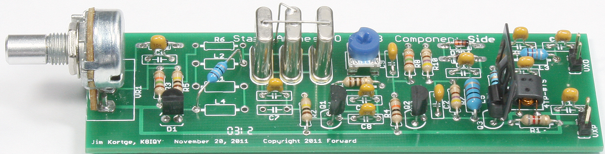
The Four State QRP Group is pleased to announce a new kit, the Stand Alone VXO (SAVXO) designed by Jim Kortge, K8IQY. The very complete manual, specifications, and ordering information can be found here http://www.wa0itp.com/savxo.html PayPal is accepted. It is shipped with 40M components but can easily be used on any HF band.
This is a Super VXO design which has it’s origins in the Super VXO of the SS-40 receiver. It is crystal controlled yet combines frequency agility with smooth stable tuning, and NO perceptible drift – even from a cold start. It is ideal for driving your NS-40 or other crystal controlled transmitter or receiver, and is also a great starting point for a transmitter strip of your own design. As kitted the SAVXO will put out over 250mW by itself, plenty of power to operate QRPp if desired.
All proceeds go to fund OzarkCon. As always thank you for supporting the Four State QRP Group. http://www.4sqrp.com/
I ordered mine! And once OzarkCon 2012 is over, I’ll be ordering a Magic Box kit, too.
72 de Larry W2LJ
QRP – When you care to send the very least!
Larry Makoski, W2LJ, is a regular contributor to AmateurRadio.com and writes from New Jersey, USA. Contact him at [email protected].
I need to follow my own advice
I went downstairs and flipped the K2 on and tuned around 40 Meters – WOW !!!!!!
After a long and full day of work, my brain is simply not ready to wrap around 40 WPM code. I worked HG3R who was cruising at about 35 WPM and called it a night. Tomorrow, after a good night’s sleep and after the opening hours pandemonium is over, I will be ready to jump into the fray. Also, during the daylight hours, stations will be spread out more as other bands open. Seems like right now, everyone is crammed into 40 and 80 Meters.
I’ve been at this Morse game for over 30 years now; and I really admire these guys who can while away at 40 – 50 WPM. I would love to be able to attain that kind of speed; but right now, it sounds more like a buzz saw than Morse Code. God bless them, you have to admire and respect that kind of ability.
72 de Larry W2LJ
QRP – When you care to send the very least!
Larry Makoski, W2LJ, is a regular contributor to AmateurRadio.com and writes from New Jersey, USA. Contact him at [email protected].
Opening thoughts about ARRL CW contest

Until then....contest on!!
Mike Weir, VE9KK, is a regular contributor to AmateurRadio.com and writes from New Brunswick, Canada. Contact him at [email protected].
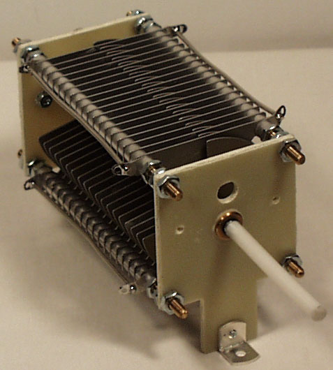
DIY Magnetic Loop Antenna – Part 1
Do you live in a neighborhood with a restrictive antenna policy and despair of having a useful HF antenna?
Can you solder or know someone who can?
A magnetic loop antenna may be the answer and they are not as difficult to build as you might think. Like getting on the air for the first time or taking your license exam there is a certain amount of uncertainty when you first approach magnetic loop antennas, there are a few new ideas to grasp. However, thanks to other hams like Steve AA5TB there are tried and tested designs, calculators & building methods that are known to work and that you can follow.
 At the heart of every radio and MLA (Magnetic Loop Antenna) is the resonant circuit. The combination of an inductor (a wire has inductance, but a coil of wire has more) and a capacitor (two conductors separated by an insulator) in a circuit will resonate or ‘ring’ at a certain frequency. Sound vibrations at a certain frequency can cause a piano string to vibrate in sympathy and a vibration of the correct radio frequency will cause a resonant circuit to electrically vibrate in sympathy.
Since there is no such thing as a free lunch, the sacrifice you make with a MLA is that it needs to be re-tuned whenever you change frequency on your transceiver. The frequency range over which it is resonant is very small, typically only a few hundred kilohertz at the most.
The materials you can get your hands on is going to decide the capabilities of your MLA. Ideally you’ll have a loop made from a conductor with very low resistance (usually copper) and a capacitor that can handle high voltages. A variable capacitor is required if you want to use your antenna on multiple frequencies but you can use or make a fixed capacitor if you operate on one frequency, for Eg PSK31.
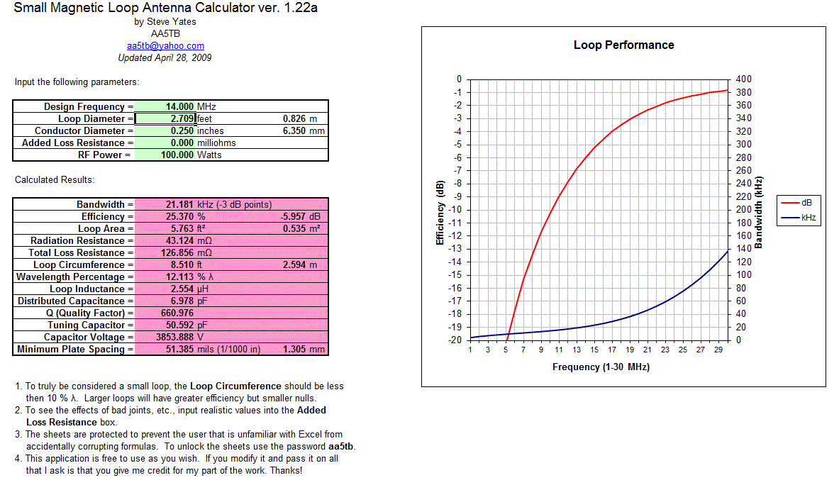
A MLA calculator like the Excel spreadsheet from Steve AA5TB or this web page from 66pacific.com will help you to decide what size components you’ll need to make your antenna.
The four pieces of information required are:
- What frequency or frequencies do you wish to transmit on?
- How large do you want the loop to be (It should have a circumference less than 10% of the design frequency wavelength, both calculators help you figure this out)
- The diameter of your conductor (Three quarter inch (0.75 inch) copper pipe is a good start)
- How much power you want to use (The voltage across the capacitor is proportional to the input power to the MLA)
 A MLA of a certain circumference will be more or less efficient based on the frequency you transmit at. It is worth changing the loop size in the calculator to get the best efficiency possible in your favorite band.
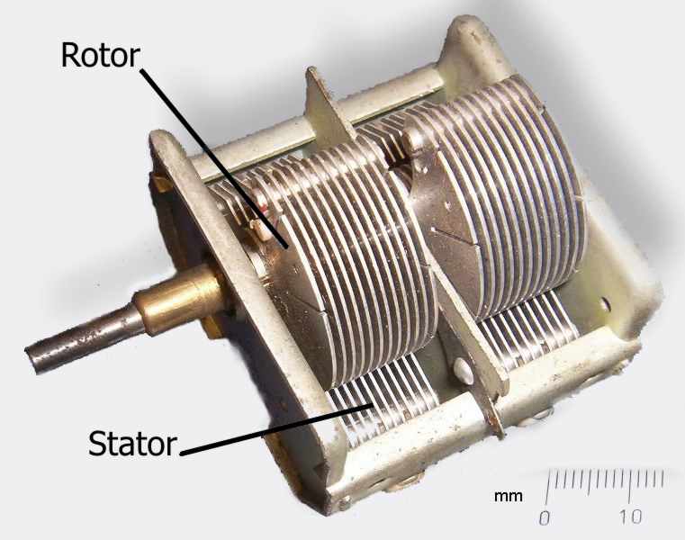
Owen Morgan, KF5CZO, is a regular contributor to AmateurRadio.com and writes from Texas, USA. Contact him at [email protected].
 Ham Radio Deluxe |
 W5SWL Electronics |
 Ham Radio Prep |
 KB3IFH QSL Cards  Hip Ham Shirts  HamRadioAuctions HamRadioAuctions Reliance Antennas Reliance Antennas Enigma Shop Enigma Shop |  morseDX  Ni4L Antennas  R&L Electronics R&L Electronics antennas.us antennas.us QRV QRV |
- Matt W1MST, Managing Editor
