 |
 EICO Model 625 Tube Tester
I attended the Greater Houston Hamfest and as I walked past the tables of equipment I wondered if interest in vacuum tube equipment was starting to wane. Compared to the last few years the prices of collector quality gear had held steady but parts and restorable gear seemed to be going for less. I’d like to know your thoughts if you’ve noticed trends one way or the other.
I was happy to pick up a EICO Model 625 tube tester for $15. It is in good condition and appears to work well. The roll of settings for each tube is in good condition and a little searching on the internet supplied settings for older tubes like the number 78 in the picture below.
 |
| EICO Model 625 Tube Tester with a number 78 tube |
The EICO 625 is not a top of the line tester but it does basic tests and will let you know if a tube is functioning and an idea of the life left in it. It was sold in kit form for $34.95 in 1958 which is roughly equivalent to $274 in 2012.
 |
| Inside the EICO 625 from diyaudioprojects.com |
The EICO 625 is fairly unique in having its own 6H6 diode tube to rectify the 30V filament voltage. It provides DC for the neon short-indicator bulb. If the tube is suspected of having a short then there is a fairly comprehensive series of tests than can be administered to isolate shorted elements.
 |
| EICO Model 625 circuit diagram |
Here is the complete TUBE TEST DATA 1/1/78 for the EICO Model 625 Tube Tester
Excellent information on servicing and calibrating your Classic emission tube tester.
Owen Morgan, KF5CZO, is a regular contributor to AmateurRadio.com and writes from Texas, USA. Contact him at [email protected].
W1GHZ 903-MHz TX Gain Compression

I managed to sneak into the lab again at lunch today for a few minutes and hooked up the now-packaged W1GHZ 903-MHz transverter to do a transmit gain compression test. This test is a quick and dirty way to find the linear operating region of the transverter in addition to the expected conversion gain on transmit. These two parameters determine the IF transmit level and what kind of power amplifier or driver stage will follow. It’s an easy test to run if you have the equipment. I locked the transverter in transmit by applying 8 volts to the TX MMICs and used a Rodhe and Schwarz SMR40 signal generator as the IF transmitter at 147.100 MHz. On the transverter TX output, I simply connected the HP 8565E spectrum analyzer that I’ve used in the past. Spectrum analyzers are not great power meters, but they give you a good enough idea of what’s going on. The 1-dB gain compression point (that is, the point where the actual device gain sags 1 dB from the linear gain) is at an input of -3 dBm or an output of just under 10 dBm. This compares favorably with the datasheet for the mixer and discussion with N3UM.
Ethan Miller, K8GU, is a regular contributor to AmateurRadio.com and writes from Maryland, USA. Contact him at [email protected].
LHS Episode #077: North of the Border
 Today Linux in the Ham Shack is graced with the appearance of an additional co-host: Harrison, VE2HKW, an amateur radio operator from Canada and sometimes host of the Mintcast, a podcast for Linux users from members of the Linux Mint community.
In the first segment, our hosts discuss three very useful Linux utilities for analyzing system performance on your desktop or server: iftop, ifstat and iotop. Get in-depth knowledge of how to use these tools in order to make your machine run better with fewer bottlenecks. And since Harrison is from a whole other country, it was decided he should tell all of us about amateur radio from a Canadian perspective, including licensing, regulations and operating practices.
Hamvention 2012 is coming up very soon. Please donate to the fund if you can. We hope to see everyone there!
73 de The LHS Guys (and Harrison, too)
Russ Woodman, K5TUX, co-hosts the Linux in the Ham Shack podcast which is available for download in both MP3 and OGG audio format. Contact him at [email protected].
Drywall and DXCC Progress
If you’ve been following my ham shack updates from the past couple of weeks, you know I’m in the final stages of finishing the space in my basement which will be used as my ham shack, podcast studio, home office and overall man-cave. The space is really starting to come together and I can see what the finished space will look like. I’m truly excited and especially so after staring at nothing but stud walls for several years.
If you go back to this blog post and also read this one, you’ll get an idea of how I’ve spent the past couple of weekends. While I believe we made great progress this weekend, we did fall short of my goal of getting all the walls done. This delay was due to the extra time it took me to hang two doors. These two doors will access the utility closet I framed in to hide the HVAC systems. Because of the way the two furnaces are situated, I had to include two doors. Otherwise, should anything happen to the hot water heater, it would have required demolition to remove it.
The remaining work on the walls (about 5 more sheets of drywall) should get completed this coming weekend. I then plan to take a weekend off and reward myself (and my wife) with doing something else that weekend and then it will be time to start hanging drywall on the ceiling.
Finally, I worked a total of about two hours in the ARRL DX phone contest this past weekend. During this time I worked about 20 DX stations, adding four new to my growing DXCC list. The four new DXCC entities worked this weekend were Bahamas, Barbados, Trinidad & Tobago and Portugal. This brings me to a total of 54 DX entities worked to date.
Sorry no pictures with this update. I’ll hopefully get some pics in the next update or two showing progress.
Until then…
73 de KDØBIK
Jerry Taylor, KD0BIK, is a regular contributor to AmateurRadio.com and writes from Colorado, USA. He is the host of the Practical Amateur Radio Podcast. Contact him at [email protected].
DIY Magnetic Loop Antenna – Part 3
Well, I finally have had time to sit down and put together part three of the DIY Magnetic Loop Antenna, sorry it has taken so long!
This post will cover building and coupling the loop to your transceiver. After reading through posts one and two you should have a good idea of the parts you’ll use and the physical dimensions of the main loop.
DIY Magnetic Loop Antenna – Part 1
DIY Magnetic Loop Antenna – Part 2
Most magnetic loops have the capacitor at the top of the main loop and the gamma match or matching loop at the bottom, this arrangement avoids running the feed-line through the center of the antenna.
You can assemble the main loop from continuous copper tube or from eight straight sections and 45 degree joiners. Make sure you have a blow torch or propane torch to solder the joints as you’ll need more heat than a soldering iron can supply. Whichever way you decide to build the main loop make sure that all joints are soldered or clamped as securely as possible, you want the lowest resistance possible to avoid your output power turning into heat. Other materials can be used for the main loop such as aluminium or low loss coax but copper pipe is easy to work, has low resistivity and available from just about every hardware store.
To construct the frame of the antenna you can use PVC pipe. It is a cheap and relatively sturdy building material and is available in a range of thicknesses, just about any hardware store will stock a wide selection of fittings. It insulates well and can be glued once you are sure your project is in its final form.
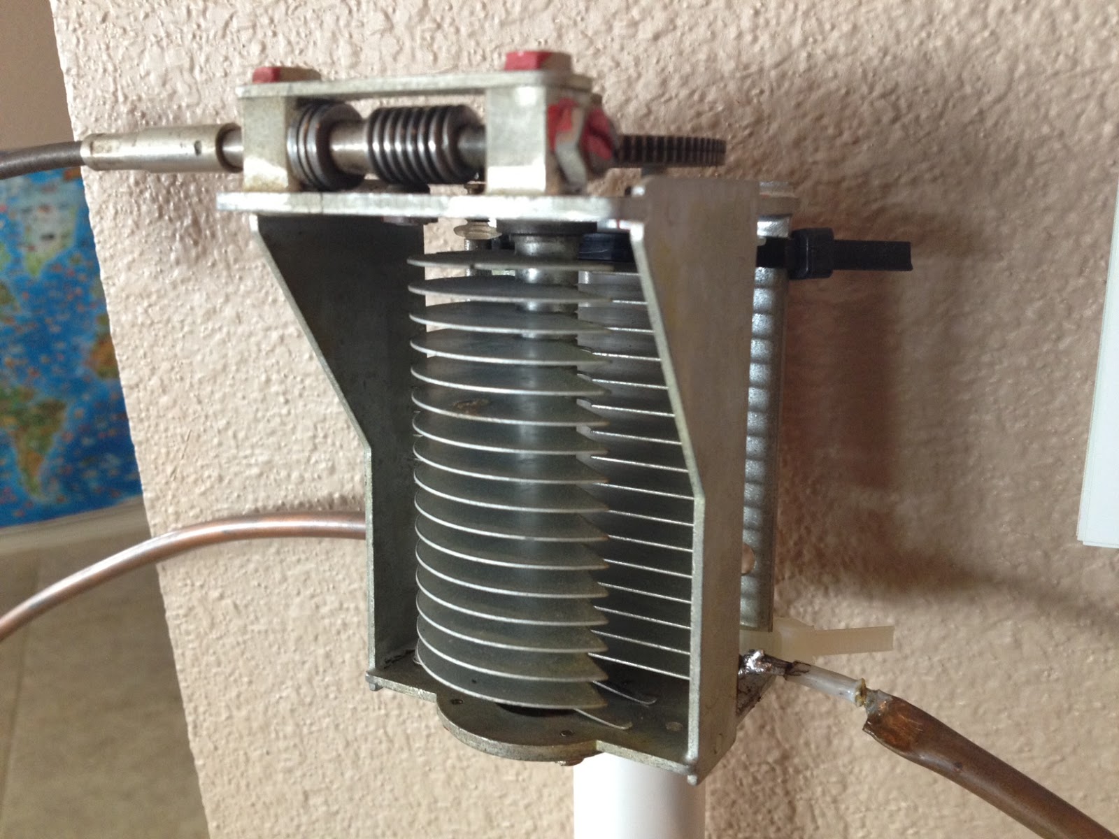
Once the main loop is constructed you’ll need to connect your capacitor to the two ends of the pipe at the top of the loop. Depending on the capacitor you may want to solder tags to the ends of the loop so they will be easier to attach. Copper pipe is a great conductor of heat and takes a lot to heat up and solder while it is not advisable to apply the same amount of heat to your capacitor.
It is also a good idea to attach the capacitor to a solid support so that the connections are not under strain.
The main loop and the capacitor forms the resonant circuit of the magnetic loop antenna.

To couple the main loop to your transceiver and match the expected 50 Ohms impedance you can use one of two methods. Probably the easiest is to use is a loop of insulated wire 1/5 the circumference of the main loop. The smaller loop is placed at the bottom of the main loop and can be shifted around to provide the best match. If you have an antenna analyzer you’ll be able to set it to the desired frequency, tune the variable capacitor for resonance and then move the small matching loop around till you have achieved close to 1:1 SWR. If you don’t have an antenna analyzer you can tune the capacitor for the greatest received noise and then on low power tweak the capacitor and move the coupling loop around for best SWR. Do NOT touch the loop while it is transmitting, use a wood or plastic rod to make adjustments as there are high voltages and intense RF fields near the loop.
An alternative to the coupling loop is the gamma match. The shield of the coax feed cable is connected to the base of the main loop while the inner conductor is connected to a point approximately 1/5 of the circumference around the loop. Its a good idea to use stiff wire (large gauge) for the gamma match as it can be critical of the position and orientation and once you have it in the right position you won’t want to move it again.
It would be preferable to have the ability to remotely tune the loop. A motor with a reduction gear could be used to move the variable capacitor but because the point of resonance is very narrow there should be a way of slowing the motor down. A simple control circuit using variable pulse width modulation could be used to slow the motor down while still retaining enough torque to move the capacitor. Whatever method is used to move the capacitor it should be well insulated from the other components of the antenna. Several thousand volts are generated on the MLA and care should be taken to ensure they don’t find their way onto control leads and back into the shack. Control leads should also be wrapped around toriod inductors as they leave the near field of the antenna to reduce the possibility of RF travelling along them.
With a SWR bridge and microcontroller you could build a fully automatic tuner that swept through the range of the tuning capacitor when the SWR rose above a defined limit indicating that the transmit frequency had changed.
With a little creativity and knowledge you could have an impressive MLA the equal of multi-thousand dollar military style units.
Hopefully this has given you some ideas for constructing your own loop antenna. Regardless of if you go top-of-the-line and buy a vacuum variable or build for economy and QRP you’ll have a compact, useful and unique antenna.
Owen Morgan, KF5CZO, is a regular contributor to AmateurRadio.com and writes from Texas, USA. Contact him at [email protected].
Code academy
As I am messing around with Arduino and its various bits and pieces I noticed quite quickly that whilst I can look through a bunch of code and pick out familiar items like serial.print and lcd.print. They seem fairly self explanatory to me. Other commands and, I’m going to call them words but you’ll understand why in a minute, just seemed a world away from my vocabulary.
My background is mechanical engineering, so limits and fits, materials, stress and strain are the areas of vocab I’m familiar with. Calling functions, variables and strings needed a bit more explanation in my world and previous attempts at understanding this went a bit wrong as there the language is the barrier. By language in this sense I mean C++, VB etc. See its getting complicated already!
If its all getting too much for you then try Codeacademy. I’ve had a few lessons with the primary idea of  learning the lingo and nothing else really. The lessons are very well structured and the little exercises that go with them as well as the projects help to test your knowledge. I’m still finding that its worth while writing things down in a notebook but understanding the difference between a function and a variable has helped me get my head round a new subject for me. I will never be a code ninja but being able to understand more than a few keywords in someone else’s code will undoubtedly help me get into the position where I can look through other peoples code and understand what is going on as well as adapt it if necessary for my own purposes.
Alex Hill, G7KSE, is a regular contributor to AmateurRadio.com and writes from Cumbria, UK. Contact him at [email protected].
It’s been one of those weeks………..
 |
| This is the powerport box without the battery |
Mike Weir, VE9KK, is a regular contributor to AmateurRadio.com and writes from New Brunswick, Canada. Contact him at [email protected].
 Ham Radio Deluxe |
 W5SWL Electronics |
 Ham Radio Prep |
 KB3IFH QSL Cards  Hip Ham Shirts  HamRadioAuctions HamRadioAuctions Reliance Antennas Reliance Antennas Enigma Shop Enigma Shop |  morseDX  Ni4L Antennas  R&L Electronics R&L Electronics antennas.us antennas.us QRV QRV |
- Matt W1MST, Managing Editor
