 |
 An APRS handheld to play with….a look at the Kenwood TH-D72E
A few weeks ago, I mentioned when I was talking about how you couldn’t really have too many handheld radios, I said that I would like to have a play with one of the GPS equipped, APRS handhelds. I didn’t say so at the time, but very shortly after that, I did have that chance!
I was doing some work on some APRS equipment for a review for Practical Wireless that you’ll be seeing soon in the magazine. However, along with what I was reviewing, David Wilkins G5HY of Kenwood Electronics very kindly popped a TH-D72E into the box of gear to look at. David said it was partly a safety net to be sure that I could do some full tests on the other equipment, but very kindly that he’d also seen my blog!
Well! I can now admit that the TH-D72E was the very first thing unboxed! It’s a nicely sized handheld and I found it easy to use. I used it mostly in its’ APRS capacity, although I did play around a little with it as a regular handheld and used it through the GB3UK repeater on Cleeve Hill. That worked fine and I found I was able to get a good solid signal into the repeater at 5W.
What I was really intrigued about was whether the MB7UC APRS digipeater on Cleeve Hill on 144.800 would hear my packets. I was pleased to find that the GPS locked up pretty quickly and established my position, even inside, though some times it would take a minute or more which was no big deal. I set the beacon so that it would be transmitted once every half hour (that felt right for this experiment).I left the handheld on the upstairs windowsill that ‘sees’ towards Cleeve Hill. Although I received the odd packet from MB7UC and it received the odd packet from me, there was not much. This illustrated the difference between a handheld antenna and having a collinear at 30 feet – on which the digipeater is very loud indeed.
I took the TH-D72E over to Cheltenham when visiting my Mum and was excited to get lots of packets through the handheld, digipeated through MB7UC including some from a Search and Rescue boat in the Severn Estuary! Very cool! And of course, being closer to the digipeater it happily heard my APRS packets and digipeated them.
How could I make it better from home and get a bit more coverage? Well, I then setup the Kenwood TM-D710E which I had as part of the review work as a digipeater and connected it up to the collinear. Now when I went out for a walk with the TH-D72E and it sent an APRS packet, the digipeater at home would repeat it and it could then be heard by the digipeater on Cleeve Hill – and a couple of others too! It was good to hear the satisfying beep of the handheld as it saw My Position being digipeated through other APRS digipeaters. Fun to come back and look on APRS.FI and see where I had been!
The Smart Beaconing feature on the TH-D72E was good and sent a beacon at appropriate intervals depending on how fast I was moving (on foot or on the bike – don’t worry, David – it was a mountain bike – not a motorbike!).
Lots of fun! The only thing that was slightly disappointing was the lack of a good APRS digipeater in this area – which would make the experience even better! But that’s hardly the fault of the TH-D72E! I also experimented with sending messages to and from other APRS stations which was good – and even sent a message to my pal Steve, WG0AT in Colorado – and his goats, Peanut and Rooster of course!
Battery life was pretty good, although not as good as some of my other handhelds. It was in line with the manual though and I think the reason for the relatively short time (between 5 and 10 hours between charges when APRS beaconing) was not only the regular beacon, but also the GPS which are pretty notorious for sapping battery life (the iPhone comes to mind!).
The TH-D72E is a ‘substantial purchase’ at over £400 – but there is a lot of additional technology compared to a more standard handheld – the packet TNC and the GPS all built into a small package that will easily fit in your pocket. This is surely how the mainstream manufacturers can compete, by putting extra value technology such as APRS/GPS or Digital modes like DSTAR – into their products. At £400 you really have to want to play APRS and have a nice GPS on your radio – but I can certainly recommend the TH-D72E – I thoroughly enjoyed playing with it and I’m sorry to have to give it back! Thank you, David!
Now what should I casually mention that I’d like to play with next……
Tim Kirby, G4VXE, is a regular contributor to AmateurRadio.com and writes from Oxfordshire, England. Contact him at [email protected].
Hermes HPSDR comes to MX0WRC
Last night was club night. Its a good chance to catch up in person with the local hams and exchange bits of useful information. Normally how to fix the things I have broken, which seems to be quite a few things at present including 3 bikes, but that’s another story.
Kevin, M0KHZ came along with the view of giving us an understanding of where the Hermes High Performance Software Defined Radio (HPSDR) is. He started with a brief history which explained for us lesser mortals how the project got started and how the project team got to where they are today.
The prototype that was on display at Dayton and Friedrichshafen was fired up and Kevin showed us how the rig could be controlled over wifi and the potential of Hermes to take SDR to the next level and then further. Even though Kevin was tight lipped I got the impression that this was not the end of development
The detail is way over my head and the likelihood of me understanding these concepts fully is fairly slim but it doesn’t stop me wanting to get my paws on one. Needless to say I have approached the local financier / XYL who was less than interested so there’s more ground work needed there. The impression I got was that although there is a fairly full ‘expression of interest’ list at HamSDR (you’ll need to log in to add your name to the list) the commit to buy list isn’t yet up and orders are not likely to be taken until September. Plenty of time to save up.
SDR doesn’t fill everyone with the same excitement as it does me but its fair to say that whatever your stance you can’t fault this small project team for their dedication and know how as well as doing this not for commercial gain.
Alex Hill, G7KSE, is a regular contributor to AmateurRadio.com and writes from Cumbria, UK. Contact him at [email protected].
Activation Alert: WØ/FR-003 (Mount Evans) –4347m / 14,264ft
Date: 3 July 2012
Time: Approx. 1700 UTC – 1800 UTC
Region: CO-Front Range
Elevation: 4337 m / 14,264 ft – 10 Points
Call Sign: KDØBIK
Frequencies: 14.342.5-ssb, 18.157.5-ssb, +/- 146.52-fm
Equipment: Elecraft KX3 (2nd activation / Buddipole versatee vertical
APRS Track: On Road / On Trail
My wife and I are on a staycation (vacation at home) this week and while I’ve spent some time working on the new basement ham shack, I also wanted to take a much needed break and go and explore a portion of Colorado I’ve never had the opportunity.
Mount Evans is very near I-70, I’ve driven past many times and I can see it from my office building in the Denver Tech Center. It is much like Pikes Peak in the sense that there is a paved road almost all the way to the top. I’m going to take my wife along for this SOTA adventure. We’ll drive to the top and I’ll hike down far enough and then back up to call it a legal SOTA activation and hopefully make a few HF contacts and take in the beauty of Colorado. We’ll then probably go to lunch in Idaho Springs. Perhaps Beau Jo’s Pizza.
Please listen for me on 20m around 1700 UTC (11 AM MT). I look forward to working you.
By the way. My Grandfather’s family name (and my Mom’s maiden name is Evans). I’ll be dedicating this SOTA activation in my Grandfather’s memory. If successful, this will be the first SOTA activation on Mount Evans.
Until next time….
73 de KD0BIK
Jerry Taylor, KD0BIK, is a regular contributor to AmateurRadio.com and writes from Colorado, USA. He is the host of the Practical Amateur Radio Podcast. Contact him at [email protected].
Front panel work
Tonight I spent getting the front panel assembly done. I haven’t attached it to the main chassis yet. I stopped after completing the panel itself as I’m a bit tired.
Two things that caused beads of sweat to pop out on my forehead.
1) The four screws that hold down the LCD cover bezel. The first step, before even thinking of securing the bezel is a step that Elecraft calls, “removing the paint from the screw threads in the holes”. I think that’s Elecraft just being nice and faking us out. I don’t think there were any threads to get gunked up with paint, to begin with. You’re cutting these threads by inserting these screws!
Elecraft recommends wetting the screw’s threads with “a drop of water” (oil can leave marks that can be difficult to clean up). I didn’t feel like getting up to get a cup of water, so I did the next best thing. I stuck the screws in my mouth. Not the most sanitary, I suppose, but oddly effective. Only one screw hole gave me trouble where I was worried about rounding off the screw; but firm pressure while very slowly torquing the screw did the trick in the end.
2) Mounting the mated Front Panel circuit and DSP circuit to the front chassis panel. In the manual, Elecraft states that it’s a tight fit for the phones socket through the hole in the front panel. Wow! I’ll say! I finally got it through with some firm pressure but when the socket hit the back of the front panel, I got a loud “snap” from metal hitting metal. For a second I thought I broke the circuit board, but a careful inspection revealed that all was well.
Other than those two panic moments, all went well. Tomorrow, I will continue mounting the front panel to the chassis, and I may even get to the point where I get to do an initial power up.
Six man hours into this, so far.
72 de Larry W2LJ
QRP – When you care to send the very least!
Larry Makoski, W2LJ, is a regular contributor to AmateurRadio.com and writes from New Jersey, USA. Contact him at [email protected].
It’s time for surgery………..
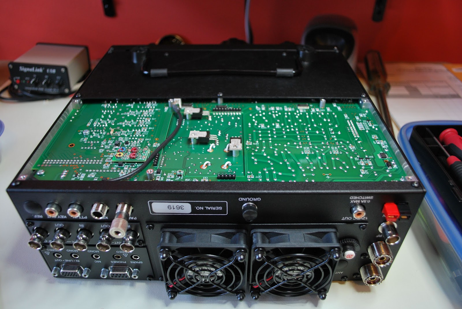 |
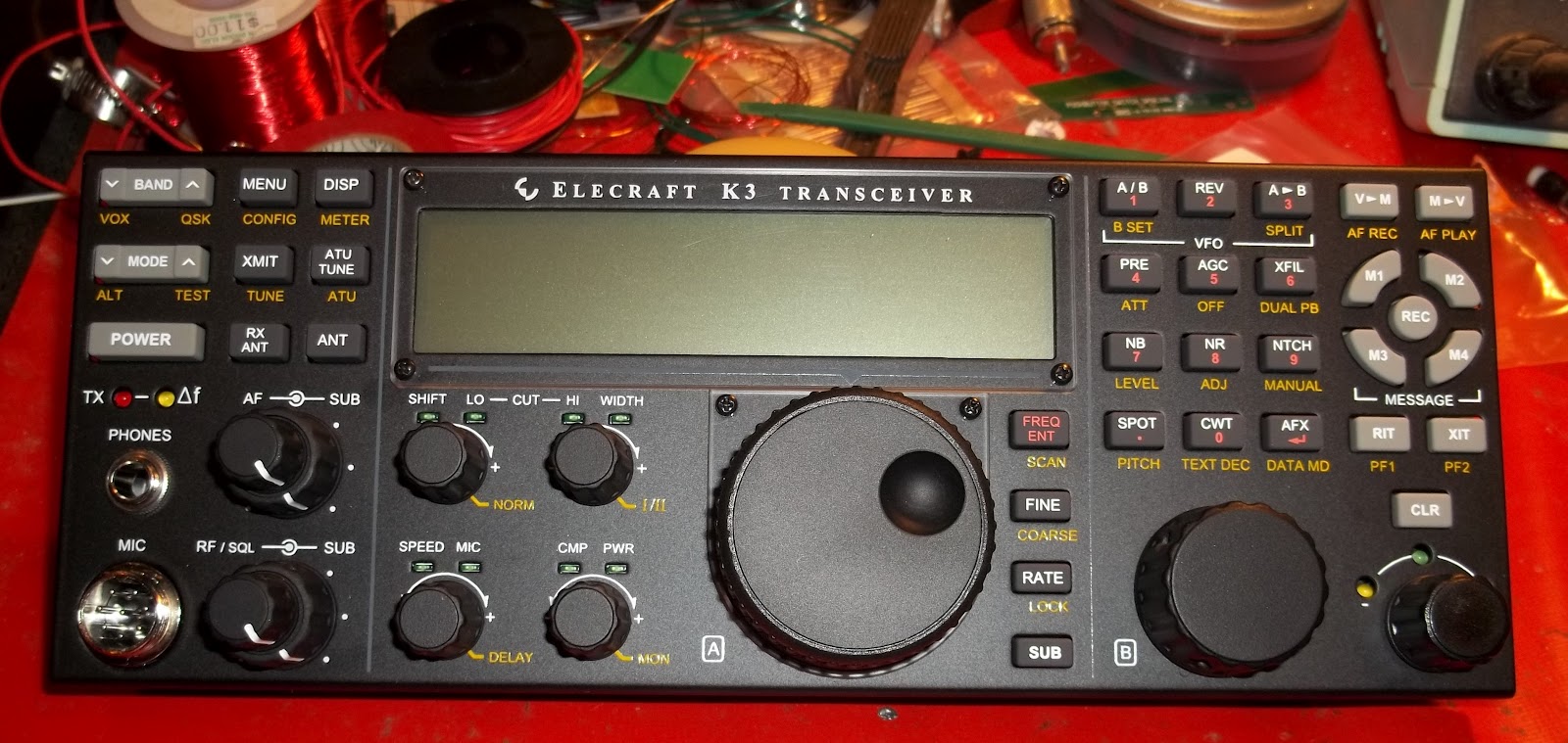
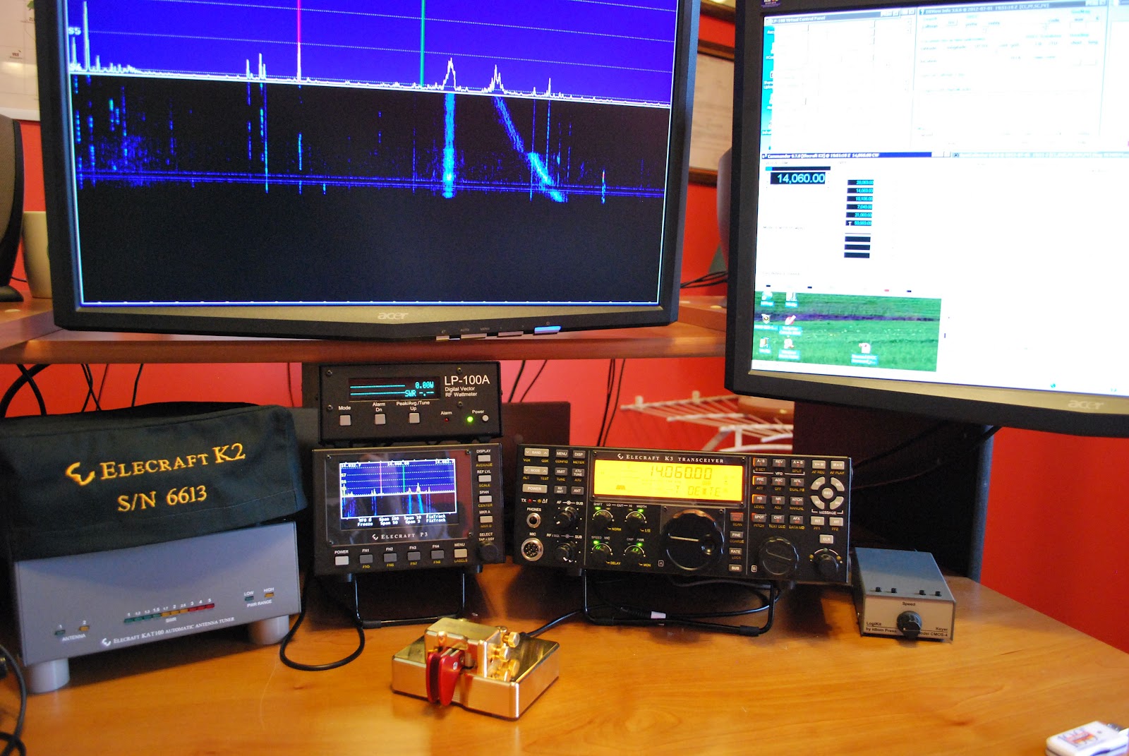
| Ready for action |
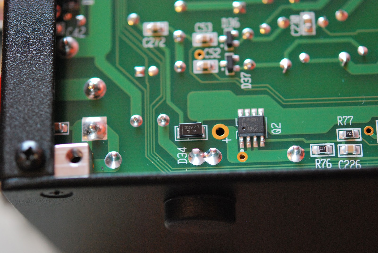 |
| Diode to be removed |
 |
| Fans removed |
 |
| KPA3 removed |
very little trouble. Installing the new one was another story and it did take me several attempts. When all was said and
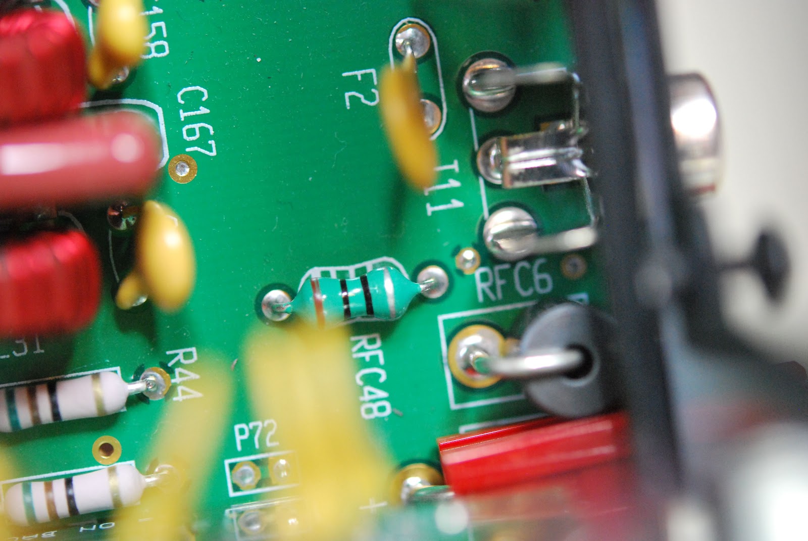 |
| Old F2 and RFC 48 |
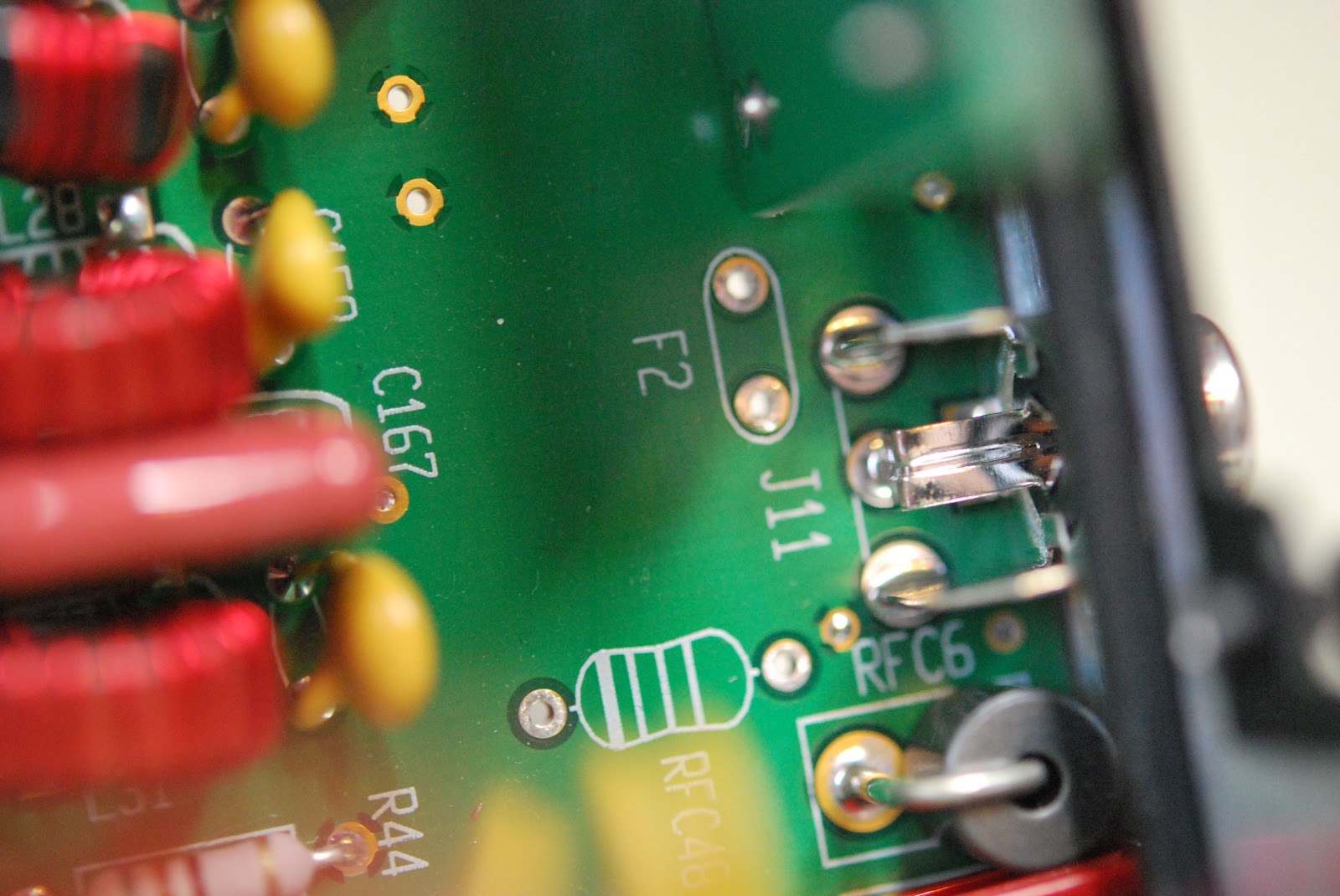 |
| Ready for new parts |
instructions did say the KPA3 unit did not have to be removed if you were very very careful it could be done. Not feeling at all brave out came the KPA3 unit as well. The inductor and resettable fuse that had to be replaced were in plan view and HUGE compared to the SMT diode. I now had to DE-solder the two components and this is were the Hakko 808 was stellar. In under 30 seconds both component were
 |
| Great tool to have |
 |
| back home and working |
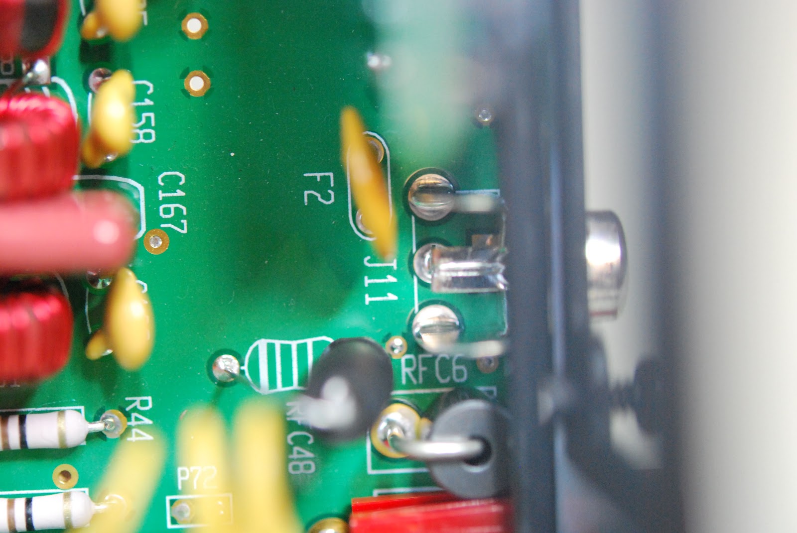 |
| New parts installed |
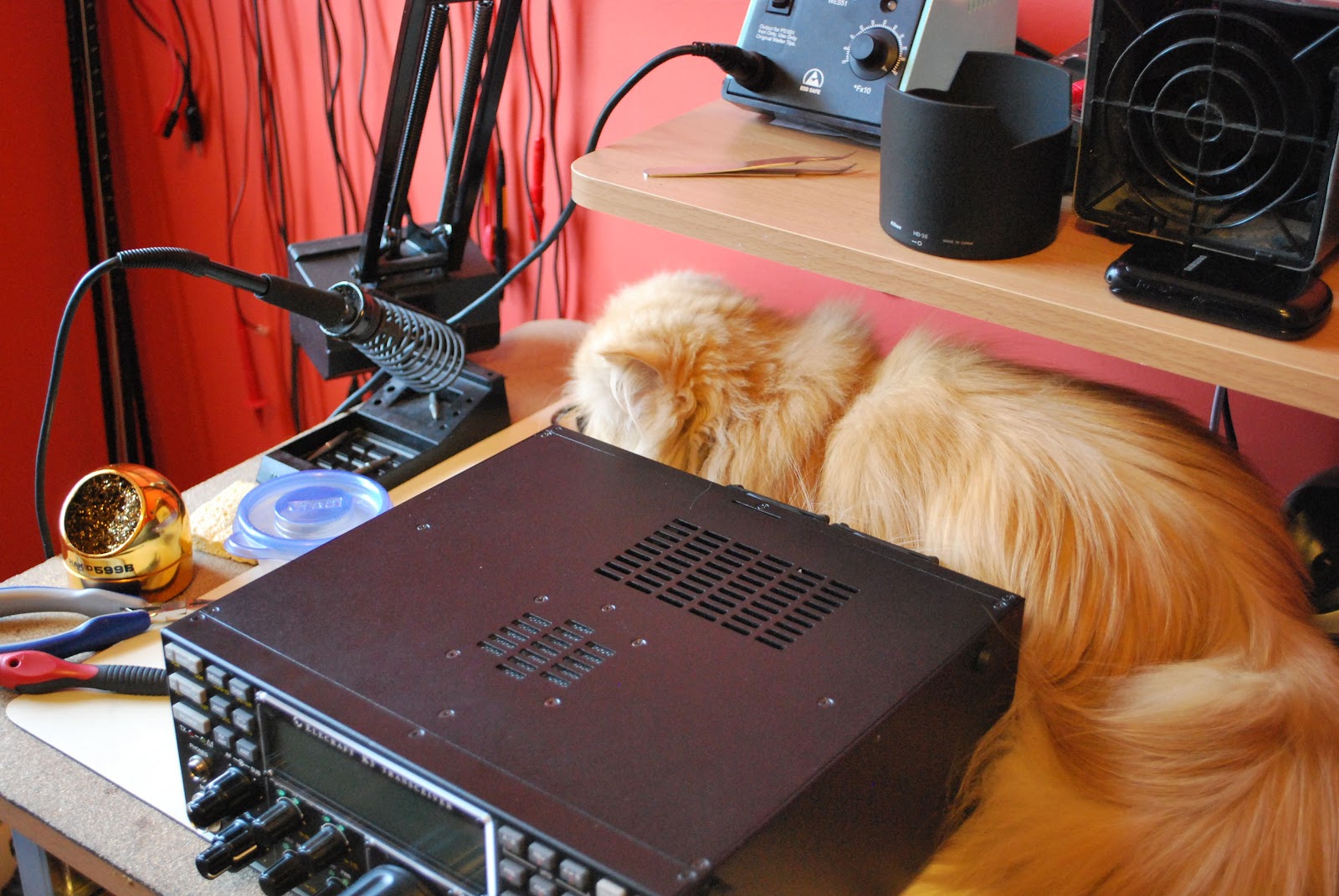 |
| Oliver gives the ok to power up |
Mike Weir, VE9KK, is a regular contributor to AmateurRadio.com and writes from New Brunswick, Canada. Contact him at [email protected].
Software Defined Radio receiver for £13? Why yes, I will?
I’d been peripherally aware for a few weeks that some people had been doing clever things turning USB TV sticks into Software Defined Radios, but other than mentally noting it as something to look into when I got a moment, I’d done no more.
The critical moment came this afternoon when Richard G4WFR tweeted that he’d been having some fun over the weekend with one of the sticks. I quickly asked him which USB stick he’d used, which he told me was a Newsky TV DVB stick (eBay number 110898287043). The critical thing is that the USB stick must have the RTL2832U chip & E4000 tuner in it. Managed to order one of those sticks for £13 including postage, so I’m looking forward to it arriving.
Richard is using the SDRSharp (SDR#) software which can be downloaded at http://www.sdrsharp.com/index.php/downloads – although I think I have seen people using other software. Richard mentions that a special driver for the USB stick is required, which can be downloaded from this site, rather than the supplier USB driver.
Richard mentions that he is getting coverage between about 60MHz and 1.7GHz with useful sensitivity. If I can do the same, I’ll be happy. Once it arrives, I’ll have a go at hooking it up and see what mischief I can get up to with it.
More soon.
Richard G4WFR has just put together some notes on his experiments so far, which look very useful
Tim Kirby, G4VXE, is a regular contributor to AmateurRadio.com and writes from Oxfordshire, England. Contact him at [email protected].
Getting going
I started the afternoon by working K2I, the 13 Colonies Special Event station for New Jersey, who turned out to be located in Greenbrook, New Jersey – all of about two towns over. Go figure!
The I turned the radio off and concentrated on the K3 build. Not known for my prowess in being able to walk and chew gum at the same time, I figured it was better if I avoided any HF distractions.
The KX3 and K3 builds are amazingly similar in some ways. The manuals are well thought out as always – this has become an Elecraft “standard”. The build starts off by attaching 2D fasteners to the main or RF Circuit Board. The chassis and housing are literally built up around this all important circuit.
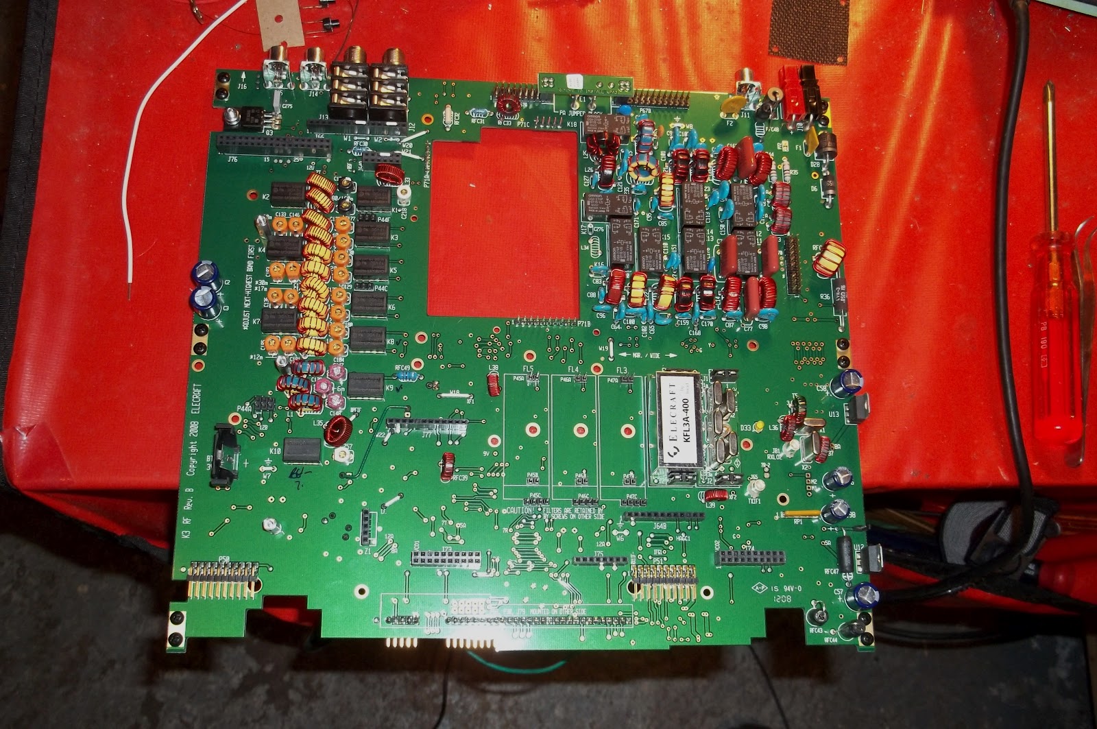
From there, things get added, like the filters. I have the standard 2.7Khz 5 pole filter and the 8 pole 400 Hz roofing filter.

These just go onto their edge connectors and then are secured by a screw and lock washer. For the various modes and bands, there’s space for up to five filters. I only have the two installed.
Next came the low power Power Amplifier board. This occupies the big hole you see in the upper center of the first photo.
As far as this K3 goes, that’s it. This will be a QRP version, so whatever I get out of this circuit is what I will be sending out to the world.
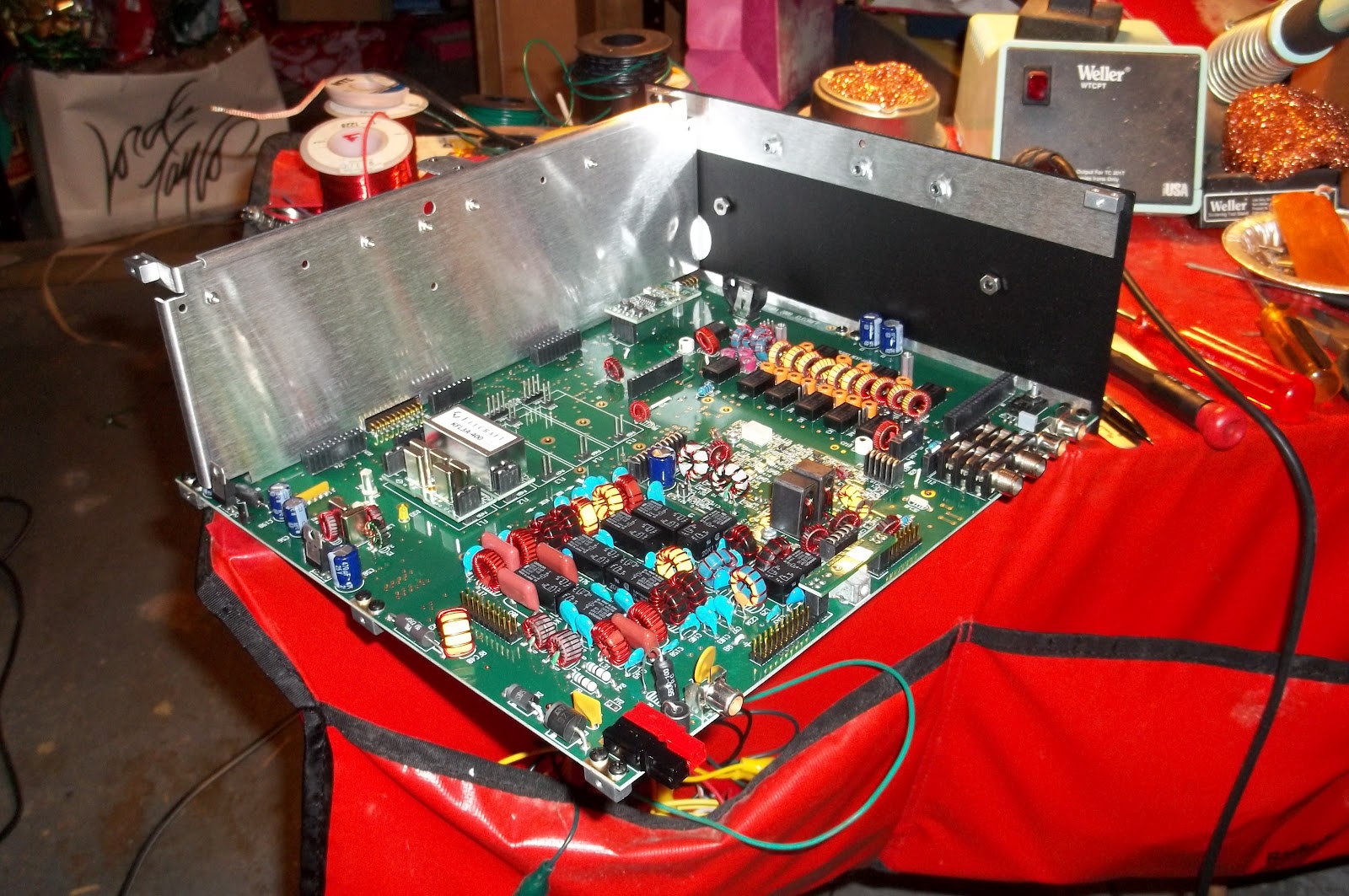
The next step is to start adding sides, and now this is beginning to look more like what you’d expect a radio to look like.
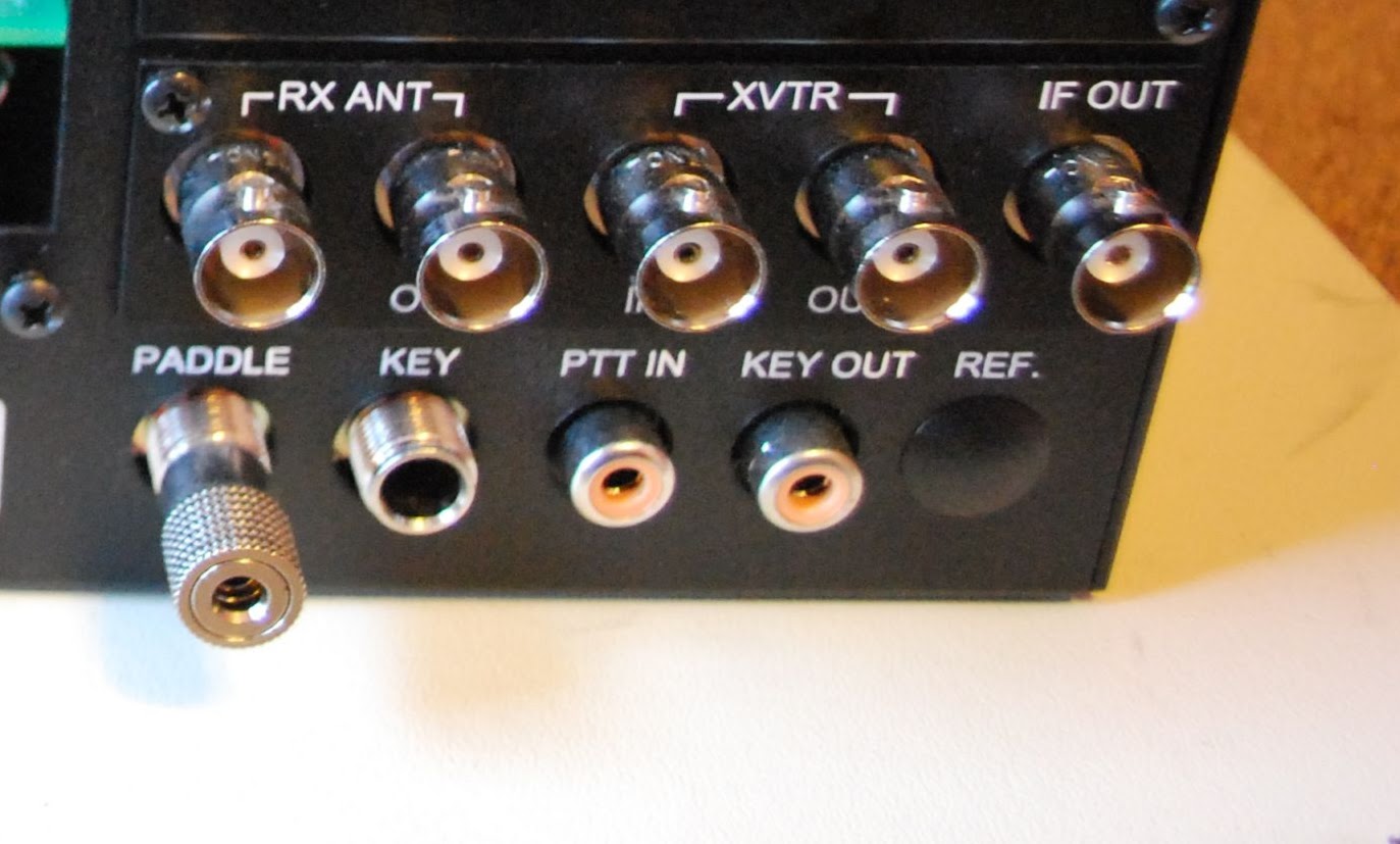
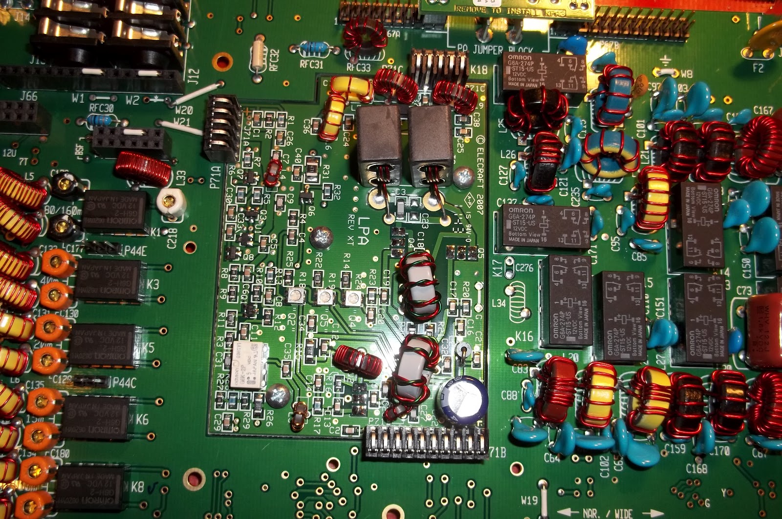
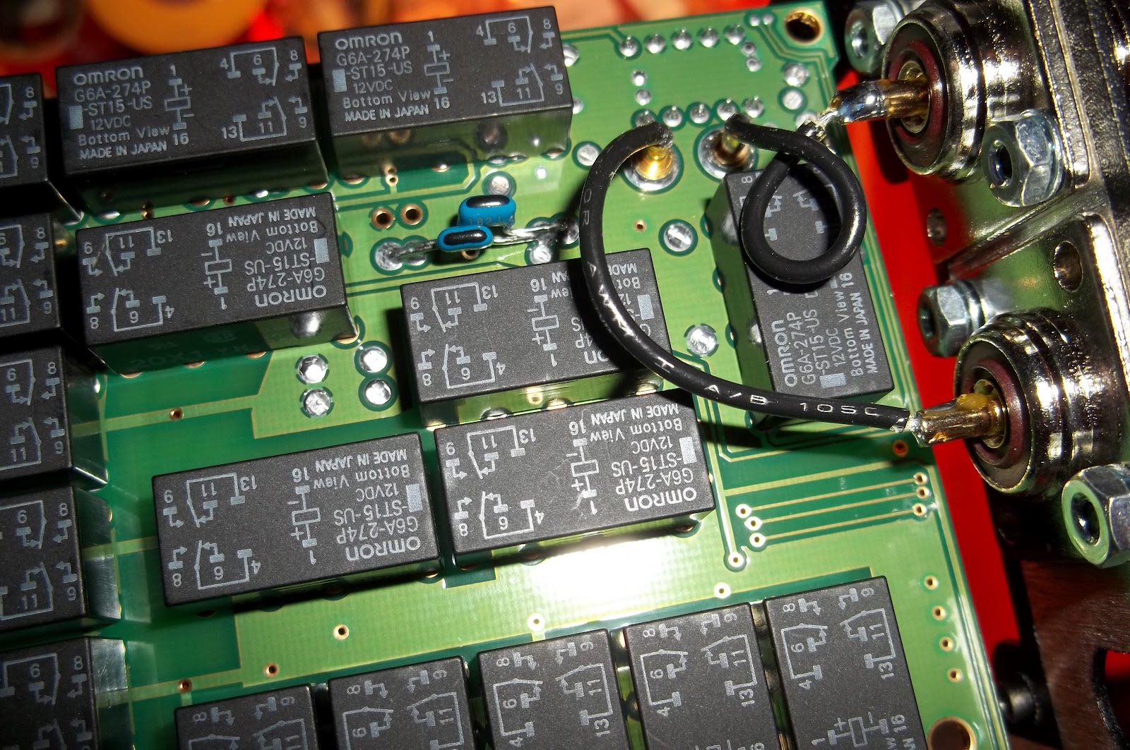
Installing the Auto Tuner came next. That in itself was easy. it just plugs into the main RF Circuit and is secured by hardware.
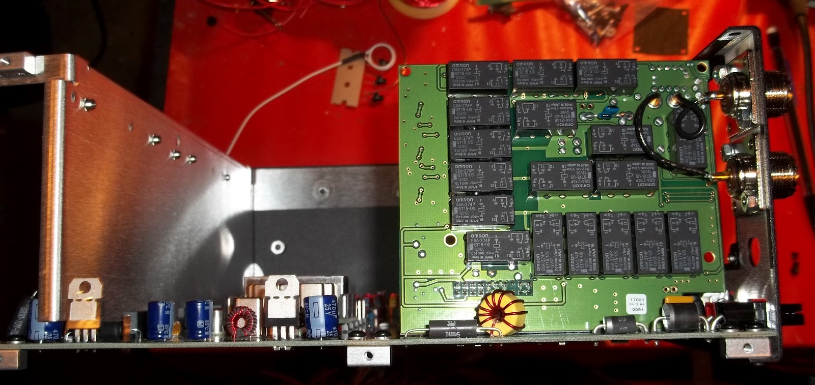
The hard part was getting the SO239 connectors plugged in. As you can see in the close up below, there are wires that get plugged into two brass sockets on the auto tuner board. The one wire slid into the socket on the left as smooth as butter. The one on the right was way more picky. I had to make sure the alignment of pin with socket was perfect. Then, and only then, did it go in – and even that took some effort.
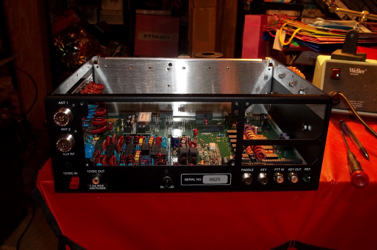
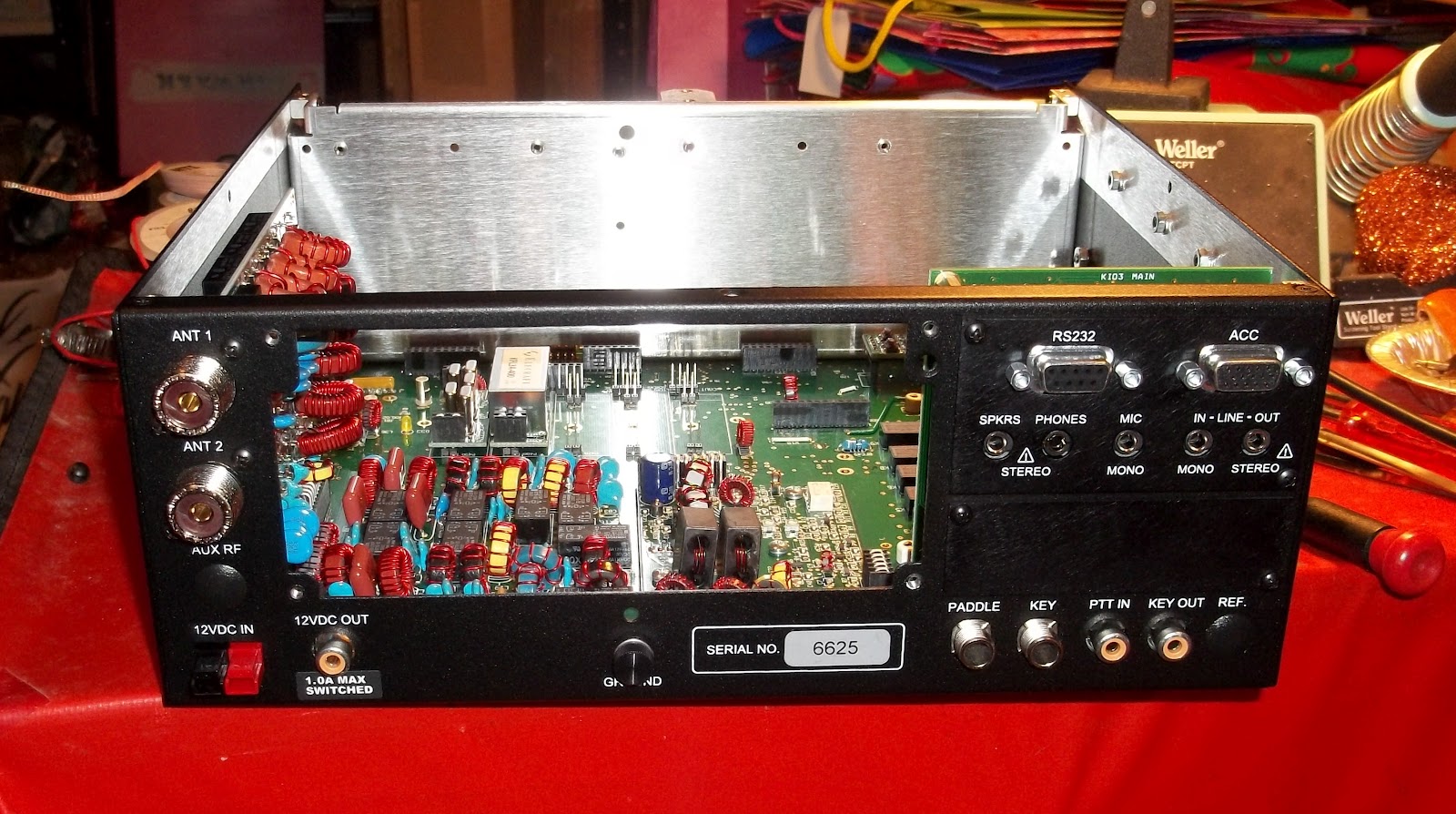
It is looking more and more like a real radio. And at this point, this is where I chose to stop for the night. I have put in about four hours worth of work so far. Tomorrow night, if I am not exhausted after work, I will begin work on the front panel.
72 de Larry W2LJ
QRP – When you care to send the very least!
Larry Makoski, W2LJ, is a regular contributor to AmateurRadio.com and writes from New Jersey, USA. Contact him at [email protected].
 Ham Radio Deluxe |
 W5SWL Electronics |
 Ham Radio Prep |
 KB3IFH QSL Cards  Hip Ham Shirts  HamRadioAuctions HamRadioAuctions Reliance Antennas Reliance Antennas Enigma Shop Enigma Shop |  morseDX  Ni4L Antennas  R&L Electronics R&L Electronics antennas.us antennas.us QRV QRV |
- Matt W1MST, Managing Editor
